Language selection

Search

Patent 1328311 Summary

Third-party information liability

Some of the information on this Web page has been provided by external sources. The Government of Canada is not responsible for the accuracy, reliability or currency of the information supplied by external sources. Users wishing to rely upon this information should consult directly with the source of the information. Content provided by external sources is not subject to official languages, privacy and accessibility requirements.

Claims and Abstract availability

Any discrepancies in the text and image of the Claims and Abstract are due to differing posting times. Text of the Claims and Abstract are posted:

  • At the time the application is open to public inspection;
  • At the time of issue of the patent (grant).
(12) Patent: (11) CA 1328311
(21) Application Number: 1328311
(54) English Title: PROTECTION CIRCUIT FOR OPTICAL DISC PLAYERS
(54) French Title: CIRCUIT POUR LA PROTECTION DES LECTEURS DE DISQUE OPTIQUE
Status: Term Expired - Post Grant
Bibliographic Data
(51) International Patent Classification (IPC):
  • G11B 7/00 (2006.01)
  • G11B 19/02 (2006.01)
  • G11B 19/06 (2006.01)
  • G11B 19/10 (2006.01)
  • G11B 23/28 (2006.01)
  • G11B 33/10 (2006.01)
(72) Inventors :
  • LEE, RAE HWAN (Republic of Korea)
(73) Owners :
  • RAE HWAN LEE
(71) Applicants :
(74) Agent: MARKS & CLERK
(74) Associate agent:
(45) Issued: 1994-04-05
(22) Filed Date: 1989-07-05
Availability of licence: N/A
Dedicated to the Public: N/A
(25) Language of filing: English

Patent Cooperation Treaty (PCT): No

(30) Application Priority Data:
Application No. Country/Territory Date
1988-10968 (Republic of Korea) 1988-07-05

Abstracts

English Abstract


ABSTRACT OF THE DISCLOSURE
A protection circuit for optical disc players which can
prevent the unnecessary radiation of laser beams due to a
malfunction of the player. The circuit includes a laser
radiating and detecting means which detects the laser beams
reflected from an optical disc and a driving means which
receives the detected signal from the laser radiating and
detecting means and controls a microcomputer to cut out the
supply of a driving voltage to the laser radiating and
detecting means when the optical disc is not placed on a disc
table.


Claims

Note: Claims are shown in the official language in which they were submitted.

The embodiments of the invention in which an exclusive
property or privilege is claimed are defined as follows.
1. A protection circuit for optical disc players
comprising:
a switching means supplying switching signal for
eject and playback modes;
a microcomputer control means for controlling the
supply of a driving voltage for the radiation of laser
beams in response to said switching signals output from
said switching means;
a radiation intensity control means driven by said
driving voltage from said microcomputer control means
and outputting a control voltage for regular intensity of
laser radiation;
a laser radiating and detecting means for radiating
said laser beams in dependence upon said control voltage
output from said radiation intensity control means and
detecting said laser beams reflected from an optical
disc, said laser radiating and detecting means outputting
a detected signal the level of which corresponds to the
radiation intensity of said reflected laser beams;
an amplifier for amplifying said detected signal output
from said laser radiating and detecting means with a
predetermined voltage gain; and
- 7 -

a driving means receiving the output of said amplifier
and outputting a start signal to said microcomputer control
means so that said microcomputer control means controls the
supply of said driving voltage output to said radiation
intensity control means.
- 8 -

Description

Note: Descriptions are shown in the official language in which they were submitted.


; 1328311
:
PROTECTION CIRCUIT FOR OPTICA1 DISC PLAY~S
The pre~ent invention relates to a protection circuit
for optical di~c players, and more particularly to a protec-
i
tion circuit which can prevent the unnecessary radiation oflaser beams due to a malfunction of the optical disc player.
In the conventional optical disc players, the radiation
of laser beams is prevented only when a door of the set is
open, the condition of which is detected by means of a eject
switch. Practically, the eject switch is turned on when the
door is closed. However, the eject switch may be turned on
due to a mechanical shock or deformation thereof even when
the door of the set i8 open, causing the laser beams to be
radiated by turning on a 6tart switch. This may cause
injury to the human body. Further, the laser beams may also
be radiated due to a malfunction even when the disc is not
safely placed on a disc table.
It i~ an object of the present invention to provide
a protection circuit for optical disc players which can
prevent the radiation of laser beams even when a start
switch is turned on so far as the disc is not placed on a
disc table of a laser disc player.
In accordance with the present invention, there i8
provided a protection circuit for optical disc players
comprising: a switching means supplying switching signals
'~ ~; ' -
.~ :- ,
,........

1328311
, .
/
for eject and playback modes; a microcomputer control means
for controlling the supply of a driving ~oltage for the
radiation of laser beams in response to said switching
signals output from said switching means; a radiation
inten~ity control means driven by said driving voltage from
said microcomputer control means and outputting a control
voltage for regular intensity of laser radiation; a laser
radiating and detecting means for radiating said laser beams
in dependence upon said control voltage output from said
radiation intensity control means and detecting said laser
beams reflected from an optical disc, said laser radiating
and detecting means outputting a detected signal the level
of which corresponds to the radiation intensity of said
reflected laser beams; an amplifier for amplifying said
detected signal output from said laser radiating and
detecting means with a predetermined voltage gai~; and a
driving means receiving the output of said amplifier and
outputting a start ~ignal to said microcomputer control means
80 that said microcomputer control means controls the supply
of said driving voltage being output to said radiation
intensity control means.
The pre~ent invention will now be described by way of
illustrative examples with reference to the accompanying
drawing, in which:
2 -
,, ~

1328311
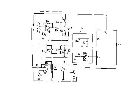
- FIG. 1 is a circuit diagram of the embodiment of the
present invention.
Referring to ~IG. 1, a switching section 5 includes an
eject switch SWl and a start switch SW2 which suppliy
switching signals to a microcomputer 6 respectively. The
switching section 5 also includes capacitors Cl and C3 for
preventing the chattering of the switches SWl and SW2 and a
resistor R6.
An amplifier 1 includes an operational amplifier OPl.
A detected signal RV output from a laser radiating and
detecting section 4 i8 applied to the noninverting terminal(+)
of the operational amplifier OPl through the resistors Rl and
R3 which determine the gain of the operational amplifier OPl.
To the inverting terminal(-) of the operational amplifier
OPl, an offset re~istor R2 is connected.
A driving section 2 comprises a switching transistor Ql
and bias resistor~ R4 and R5. The collector of this
transistor Ql is connected to the power supply B+ through the
resistor R5 and the start terminal SI of the microcomputer 6.
The detected signal RV amplified by the amplifier 1 is applied
to the base of the transistor Ql through the resistor R4.
i When the door of the set iB closed in a condition that a
¦ laser disc is not placed on a disc table, the eject switch SWl
.'~
; . .. . ... . . . . .. ., .... . . , ~ .. .. ... . ..... . .. . . . . . ..

132831
.
is turned on and an eject switching signal i8 applied to the
reset terminal RS of the microcomputer 6.
In this state, if the start switch SW2, which is a touch
type switch, is turned on, a negative pulse is applied to the
start terminal SI of the microcomputer 6, causing the
microcomputer 6 to supply a driving voltage Vc of "HIGH" level
to a radiation intensity control section 3. ~ccordingly,
the output voltage of a differential amplifying circuit
composed of an operational amplifier OP2 and resistors R7
through R10 is applied through a resistor 11 to the base of a
transistor Q2, making the transistor Q2 be saturated. Thus,
a control voltage output from the transistor Q2 is applied to
a laser diode LD in a laser radiating and detecting section
4, and laser beams are radiated from the laser diode LD. The
mark L indicates an induction coil which protects the laser
diode from being damaged. In this moment, the laser disc is
not placed on the disc table as described above, and thus no
laser beam iB reflected. Therefore, a photodetector PD can
not receive any laser beam and produces the detected signal
RV of ground level. Because the detected signal RV
of ground level is applied to the amplifier 1, the output
level thereof also becomes low, causing the transistor Ql
in the driving section 2 to be turned off.
As a result, a start signal of high level, being the
voltage level of the power supply B+, is applied from the
,~
I - 4 -

1328~11
driving section 2 to the gtart terminal SI of the microcom-
puter 6, and consequently the microcomputer 6 cut~ out the
supply of the driving voltage Vc to the radiation intensity
control section 3, re~ulting in that the radiation of laser
beams is stopped. Practically, if the start terminal SI of
the microcomputer 6 is not maintained in low level by a
predetermined period after the negative pulse produced by the
start switch SW2 is input, the microcomputer 6 will determine
as the disc is not placed on the disc table, and accordingly
will cut out the supply of the driving voltage Vc.
On the other hand, if the start switch SW2 ig turned on
after the eject switch SWl i8 turned on by closing the door
of the set in a condition that the disc is placed on the
disc table, the laser diode LD of the laser radiating and
detecting section 4 radiates the laser beams by the same :~.
operation as described above. Thus, the photodetector PD can
detects the laser bea~s reflected by the digc and produce the
detected signal voltage RV.
Thi~ voltage is applied not only to the radiation.intensity
control section 3 as a feedback signal but also to the
noninverting terminal(+) of the operational amplifier OPl
through the resistors Rl and ~3 in the amplifier 1. The
output voltage of the operational amplifier OPl is then applied
to the base of the transistor Ql through the bias resistor P4
in the driving ~ection 2, causing the transistor Ql to be
-- 5

1328311
saturated. Hence, the collector of the transistor Ql, which
i8 connected to the start terminal SI of the microcomputer 6,
is connected to ground, and accordingly the microcomputer 6
determines as the disc is plased on the disc table and
supplies the driving voltage Vc to the radiation intensity
control section 3, causing the laser diode LD to radiate the
laser beams.
From the foregoing, it will be apparent that the present
invention provides a novel protection circuit for optical disc
players which can prevent the unnecessary radiation of laser
beams even when the eject and start switches are turned on so
far as the optical disc is not placed on the disc table, and
accordingly, by the invention the human body can be protected
from injury.
~ 6 - ~-

Representative Drawing
A single figure which represents the drawing illustrating the invention.
Administrative Status

2024-08-01:As part of the Next Generation Patents (NGP) transition, the Canadian Patents Database (CPD) now contains a more detailed Event History, which replicates the Event Log of our new back-office solution.

Please note that "Inactive:" events refers to events no longer in use in our new back-office solution.

For a clearer understanding of the status of the application/patent presented on this page, the site Disclaimer , as well as the definitions for Patent , Event History , Maintenance Fee  and Payment History  should be consulted.

Event History

Description Date
Inactive: IPC expired 2012-01-01
Inactive: Expired (old Act Patent) latest possible expiry date 2011-04-05
Inactive: IPC from MCD 2006-03-11
Grant by Issuance 1994-04-05

Abandonment History

There is no abandonment history.

Owners on Record

Note: Records showing the ownership history in alphabetical order.

Current Owners on Record
RAE HWAN LEE
Past Owners on Record
None
Past Owners that do not appear in the "Owners on Record" listing will appear in other documentation within the application.
Documents

To view selected files, please enter reCAPTCHA code :


To view images, click a link in the Document Description column. To download the documents, select one or more checkboxes in the first column and then click the "Download Selected in PDF format (Zip Archive)" or the "Download Selected as Single PDF" button.

List of published and non-published patent-specific documents on the CPD .

If you have any difficulty accessing content, you can call the Client Service Centre at 1-866-997-1936 or send them an e-mail at CIPO Client Service Centre.


Document
Description 
Date
(yyyy-mm-dd) 
Number of pages   Size of Image (KB) 
Cover Page 1994-07-22 1 29
Abstract 1994-07-22 1 27
Claims 1994-07-22 2 48
Drawings 1994-07-22 1 29
Descriptions 1994-07-22 6 236
Representative drawing 2002-05-08 1 8
Fees 1997-03-11 1 58
Fees 1996-03-15 1 54
PCT Correspondence 1994-01-06 1 25
Prosecution correspondence 1992-11-30 1 29
Examiner Requisition 1992-07-30 1 54