Note: Descriptions are shown in the official language in which they were submitted.
1328S42
This invention relates to a prosthesis shaft for the
implantation of a prosthesis, especially a part of an
artificial hip, knee or finger joint by means of a bone
cement.
With conventional prostheses, the shaft which is to
be anchored within the bone has a substantially smooth
surface of conical configuration. Figures 1 and 2 illustrate
schematically by way of a hip prosthesis the retaining
forces which occur on the surface of the shaft 10 when a
force P acts on the articular head 11. These retaining
forces can be decomposed into forces of pressure (+) and
tension (-) resulting from the bonding moment of the force
P multiplied by the distance e of the direction of the force
from the shaft axis, and transverse or shearing forces (tl)
resulting from the axial force P and acting parallel to the
shaft surface. The actual load on the bone cement anchoring
the shaft results from a superposition of these compressive,
tensile and shearing forces.
It is known from EP-A-0,212,084 published March 4,
1987, to anchor a prosthesis shaft of overall conical design
by means of bone cement, the shaft surface being
additionally provided with cylindrical recesses.
Known bone cements are able to transmit forces of
pressure and tension equally well and can also accommodate
shearing forces relatively easily. But it is a significant
drawback of the known bone cements that they attack the bone
with the result that the life of the anchoring bond is
limited and that a later re-anchoring is hardly possible
because the bone is then partly destroyed.
For this reason, it has frequently been attempted to
anchor prostheses in the bones without any cement. DE-A-
2,461,339 published July 1, 1976, discloses such a
prosthesis the shaft of which is substantially formed of a
flat metal plate having its narr~w sides provided with
rounded steps within the bone. These steps are configured
so that each one has an edge face directed perpendicularly
to the trajectorially orlented spongiosa structure for
' ~ '
1328542
direct transmission of the local forces of pressure and
tension. The thus produced approximately sawtooth-like
design of the edge faces is also intended to increase the
overall area of engagement between the shaft and the bony
tissue, thereby reducing the pressures acting on that area.
However, the cement-free bonding attempted with such a shaft
requires good growth of the bony tissue so that the
sawtooth-like faces are securely embedded in the required
way. Even if this requirement is initially met, there will
always be a risk of the cement-free anchoring to loosen in
the course of time.
DE-A-3,445,738 published June 19, 1986, further
discloses a generally hollow-cylindrical bone peg having an
internal thread for receiving a bone screw and an external
surface which is formed by a plurality of large spherical
surfaces partially penetrating each other and being provided
with axial and/or transverse slots and an additional relief,
notably in the form of small spheres. This shape is
intended to achieve an intimate bond with the bony tissue
retained so that the cement-free anchored prostheical part
may be embedded by natural growth. Thus, a sufficient
growth of the bone is again a prerequisite, and there is
still the risk of the prosthetical part to loosen later on.
Recently, it has been considered to use glass
ionomers as bone cements, since glass ionomers are bio-inert
and will thus, contrary to the conventional cements, not
affect the bony tissue. Though glass ionomer-type bone
cements exhibit very good compressive strength they have but
little tensile strength and exhibit a significant brittle
fracture behaviour.
It is an ob~ect of the present invention to provide
a prosthesis shaft which may be securely and permanently
anchored within the bone by the use of a glass ionomer-type
bone cement.
In view of this object, the prosthesis shaft of this
invention is formed as a massive body and has an outer
1328~42
3a
surface formed by surfaces of a plurality of spheres
partially intersecting each other and transitional zones
between respective adjacent spherical surfaces being
concavely rounded. Thus, the shaft surface is configured in
such a way that it is exposed substantially only to pressure
and while tensile forces are substantially avoided. At the
same time edges and corners, which might lead to notch
stresses and consequently to brittle . . . . . . . . . . .
1328~42
1 fractures of the bone cement, are avoided.
Further features of the invention relate to a highly re-
liable interlocking anchoring and to avoiding such zones where
tensile or notch stresses could occur.
Embodiments of the invention will be described in detail
below with reference to the remaining drawings, in which
Figure 3 shows a hip-joint prosthesis,
Figure 4 shows a finger-joint prosthesis,
Figure 5 is a schematic illustration similar to Figure 3,
and
Figure 6 is a sectional view taken along the line A-A of
Figure 5.
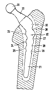
Figure 3 shows a metallic hip-joint prosthesis having an
articular head 20 joined by means of a leg 21 to a shaft gen-
erally indicated at 22. The articular head 20, the leg 21 and
the shaft 22 may be formed integrally or may be assembled, for
instance by screwing, from individual parts.
The upper portion of the shaft surface is composed of
plural spherical surfaces 23, 24, 25 intersecting each other.
The transition zones 26, 27, 28, 29 between the individual
spherical surfaces 23...25, between the uppermost spherical
surface 23 and the proximal shaft portion 30 joined to the
leg 21, and between the lowermost spherical surface 25 and
the slightly conically shaped distal shaft portion 31- are de-
26 signed as concavely rounded annular surfaces~
The shape of the shaft is based on the finding that when
a sphere is pressed into a viscous material only radial com-
pressive forces will occur. This holds even if several such
- spheres are arranged in series along the shaft axis. As indi-
cated by the symbols ~+) in the schematic illustration of
Figure 5, with such an arrangement of a plurality of spheres,
only compressive forces will occur at practically all loca-
tions in the bone cement referenced 32. When the force P shown
in Figure 5 acts on the articular ball 20, the lower half of
each sphere of the shaft will exclusively produce forces of
pressure. Furthermore, each upper sphere bears on the adjacent
lower sphere via the bone cement 32 so that compressive forces
will exist also in the region between the spheres.
:
:
r :~
1328~42
l As is furthermore apparent from the schematic illustra-
tion of Figure 5, the spheres or spherical surfaces 23...25
have radii which decrease from the proximal to the distal
shaft end, and they intersect each other only to such an ex-
tent that the centres of adjacent spheres are outside the in-
tersecting zone. Moreover it is preferable for each sphere to
have a maximum radius as far as this is permitted by the cavi-
ty 33 available within the bone. This cavity 33 is constituted
substantially by the natural cavity from which the marrow has
been removed. The inner surface of this cavity may be abraded
so as to achieve an intimate bond with the bone cement 32.
In order to prevent the prosthesis from rotating about
the shaft axis relative to the bone, at least one of the
spheres is flattened to an ellipsoid shape or formed otherwise
unsymmetrically in its cross-section as illustrated in Figure
6. To ensure the forces introduced from the torsional moments
to be reliably accommodated, this flattened body is disposed
in the middle of the shaft. In this area, additional forces
are most readily accommodated without the risk of fractures.
As shown by the sectional line A-A, the flattened body is the
central sphere 24 in the embodiment of Figure 5.
Figure 4 shows an example of a design of a prosthesis
shaft 35 for a finger joint. The shaft 35 itself is designed
substantially analogous to the shaft 22 of the hip-joint pros-
thesis of Figure 3 with a corresponding reduction in size, dueto the reduced bone length available and the smaller forces
occurring in this case, the distal shaft portion 31 illus-
trated in Figure 3 has been omitted. The proximal joint por-
tion 36 which starts from the shaft is designed in accordance
with the natural joint socket.
:'