Language selection

Search

Patent 1329147 Summary

Third-party information liability

Some of the information on this Web page has been provided by external sources. The Government of Canada is not responsible for the accuracy, reliability or currency of the information supplied by external sources. Users wishing to rely upon this information should consult directly with the source of the information. Content provided by external sources is not subject to official languages, privacy and accessibility requirements.

Claims and Abstract availability

Any discrepancies in the text and image of the Claims and Abstract are due to differing posting times. Text of the Claims and Abstract are posted:

  • At the time the application is open to public inspection;
  • At the time of issue of the patent (grant).
(12) Patent: (11) CA 1329147
(21) Application Number: 1329147
(54) English Title: ARRANGEMENT AT ROTATING FILTERS FOR IMPROVED FILTRATE DISCHARGE
(54) French Title: CONFIGURATION DE FILTRES ROTATIFS PERMETTANT D'AMELIORER LA SORTIE DU FILTRAT
Status: Term Expired - Post Grant
Bibliographic Data
(51) International Patent Classification (IPC):
  • B01D 33/21 (2006.01)
(72) Inventors :
  • NILSSON, BJARNE (Sweden)
(73) Owners :
  • BJARNE NILSSON
(71) Applicants :
(74) Agent: KIRBY EADES GALE BAKER
(74) Associate agent:
(45) Issued: 1994-05-03
(22) Filed Date: 1988-06-23
Availability of licence: N/A
Dedicated to the Public: N/A
(25) Language of filing: English

Patent Cooperation Treaty (PCT): No

(30) Application Priority Data:
Application No. Country/Territory Date
8702619-1 (Sweden) 1987-06-24

Abstracts

English Abstract


ABSTRACT
A disk filter, including a plurality of rotatable, axially spaced annular filter disks adapted to be
partially immersed in a liquid or a suspension which is to be filtered. Each filter disk comprises a
plurality of filter elements which are in communication with axial filtrate conduits arranged at the
outer peripheries of the annular disks for discharge of filtrate. For increasing the flow speed of
the filtrate in the axial filtrate conduits these slope downwards in the flow direction. This has
been achieved in that a filter element of a filter disk is displaced relative to the filter element of
the filter disk connected to the same filtrate conduit and being the following filter disk, counted in
the flow direction in the axial filtrate conduit, so that the first mentioned filter element is in
advance of the later mentioned filter element, as counted in the direction of rotation.


Claims

Note: Claims are shown in the official language in which they were submitted.

CLAIMS:
1. A disk filter, including a plurality of rotatable, axially spaced annular filter disks adapted
to be partially immersed in a liquid to be filtered, each of said filter disks comprising a plurality of
filter elements, each of said filter elements having an outlet at its outer periphery communicating
with an axial filtrate conduit extending along outer peripheries of said annular disks for
consecutively receiving filtrate from adjacent filter elements in successive disks and discharging
said filtrate in a flow direction towards an outlet of said disk filter, wherein the outlet of each
given filter element of a given filter disk is circumferentially displaced relative to she outlet of a
given filter element of the filter disk preceding, in said flow direction, said given filter disk, such
that an axial filtrate conduit communicating with said given filter element outlets inclines in said
flow direction at the time each given filter element outlet rises above a surface of said liquid.
2. A disk filter as claimed in claim 1, wherein said outlet of said filter is centrally located and
each axial filtrate conduit is connected to a substantially radial filtrate conduit, each substantially
radial filtrate conduit being eccentrically connected to said outlet of said filter, such that each axial
filtrate conduit and an associated one of said substantially radial filtrate conduits define a filtrate
discharge conduit continuously inclining in said flow direction towards said outlet of said filter.

Description

Note: Descriptions are shown in the official language in which they were submitted.


~3291~7
ARRANGEMENT AT ROTATING FILTERS FOR IMPROVED FILTRATE DISCHARGE
The present invention relates to a disk filter including a plurality of rotatable, axially spaced
annular filter disks adapted to be partially immersed in a liquid or a susp~o-nsion to be filtered,
S each disk comprising a plurality of filter elements which are in communication with axial filtrate
conduits arranged at the outer peripheries of the annular disks for discharge s)f filtrate.
A filter of this kind is described, U.S. Patent No. 4 634 529. The aYial filtrate conduits of this
filter are p}ovided with re-flow barriers for preventing so called "backwashn, i.e. re-wetting of a
10 filter cake, such as dewatered fibres, deposited on the filter elements, due to the filtrate from the
filtrate conduits running back again to the filter elements.
The object of the present invention is to improve a filter of the kind stated in the introduction, so
that the filtrate flow speed in its a~al filtrate conduits is increased to a great degree. Possible re-
15 flow barriers will thus be more effective or can be cornpletely dispensed with.
In accordance with one aspect of the invention there is provided a disk filter, including a pluralityof rotatable, a cially spaced annular filter disks adapted to be partially immersed in
a liquid to be
filtered, each of said filter disks comprising a plurality of filter elements, each of said filter
20 elements having an outlet at its outer periphery communicating with an axial filtra~e conduit
extending along outer peripheries of said annular disks for consecutively receiving filtrate from
adjacent filter elements in successive disks and discharging said filtrate in a flow direction towards
an outlet of said disk filter, wherein the outlet of each given filter element of a givell filter disk is
circurnferentially displaced relative to the outlet of a given filter element of the filter disk
25 preceding, in said flow direction, said given filter disk, such that an axial filtrate conduit
communicating with said given filter element outlets inclines in said flow direction at the time
each given filter element outlet rises above a surface of said liquid.
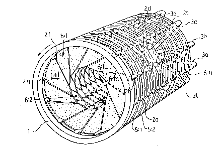
The invention will be described in the following with reference to the accompanying drawing, in
30 which figure 1 is a perspective view of a filter rotor, and figure 2 is a section thro~gh the rotor to
a larger scale taken in a direction towards its outlet end.
.
.
.~ ,
~ -
,- .

132~ ~7 2
The filter rotor illustrated in figure 1 has at one end an
exteriorly smooth rincJ l ~1hich is carried bv non-illustrated
bearing rollers. From the ring 1 there extend substantially
axial filtrate conduits 2a, 2b 2c etc. which are astened in the
ring and, at the end of the rotor facing away from the ring 1,
merye into substantially radially direct.ed filt.rate conduit.s 3a,
3b, 3c etc. These are terminated in a valve rneans 4, through
which t.he raclial~riltrat.e conduits 3 ar~d t.hereby the
correspondiny axial filtrate conduits 2 are put into
communication on~ after the other with a sucti.orl discharge
system Eor the filtrate. The axial filtrate conduits 2 are
connected by parallel annular filter di.sk holders 5:1, 5:2, 5:3
... 5:11, which carry annular Eilter disks 6:~, 6:Z, 6:~ ...
6:11. Each filter disk, e.~ t.he diæk 6:1, comprises a pluralit.y
of filtsr eleïnents 6:la, 6:Ib etc., each of which has an
unilluat.rated filtra.te o~lt..l.et b~.in~ in comrml.lni.cation ~it.h arl
axial filtrate cond~Ilt 2 vi.a a fllter disk holder 5. ~eckoIlecd i.n
the direction of rot.ation (the arrow A) of the filter rotor, t.he
arranyement is such, that a Eilter element, e.g. the element
6:1a, has communication via the filter disk holder 5:1 solely
with the followin~ axial Filtrat.e condui.t 2a, the Filter elernerlt
6:1b only with t.he concluit. 2~7, etc.
In figure 2 the filter retoL is i.lIustrated as bei.rIg il[lmert3ed in
a vessel 7 containing a liquid to be filtered. The liq~Iid
surface is denoted by 8. A collecti.on trough 9 extends through
all the filter disks. The ~al~e means 4 is adapt.ed such that. the
sub-pressure is maintained in a racIial Eiltrate conduit and its
connected axial filtrate conduit ~hen a filter elem~lnt is
approximately in a position assumed by the Ei].trate conduit 2f
and the element 6:11f i.n f:igure 2. The su`c)-ç)ressure is
maint.ained approxi.mately to the position assumed by the fi.ltrate
conduit 2b and t.he e.lement. 6:11b.
,
.
~, ,
, .
: . ' ' . .

` ~ ~72 ~ 1~7 3
- It is important that the filtrate is rapidly led away around tlle
pOSitiOIlS assumed by t.he axial filtrat.e concluits 2a and 2h, so
that it. no J.on~er rernains in the conduits when these rise
furt.her, in order to prevent the risk of it running back again
to the associatecl filter element, wh1.ch couI.d possihly t~ke
place from the conduit 2b to the elernent 6:1lb as well as frorn
the conduit 2c to the element 6:1Lc in figure 2. In accordance
with t.he inveIltion, t.herefore, the axial filtrate conduits slope
towards the outlet end during the critical part oE the time they
convey the filtrate, namely within the region closest. before and
after they leave the liquid surface (the regi.on approximately
between four and twelve o clock in figure 2~. This has been
achiev~d }~y the entire filter rotor beiny twiatect SllCh that, in
the direction of rotation, a f:ilter element sucll as the e:Lement
6:1a is somewhat in advance of the filter element of arl a(:ljacent
filter di.sk 6:2 conrlectcJcl to the SArlle axial filt.rate concIuit 2.
Effective emptying of the axial filtrate conduits is accelerated
by the slope towards t.he outlet end, this action being furt.her
increased by also the respective connecting radial filtrate
conduits sloping downwarcls towards the valve means 4, E~ee for
instance the raclial filtrate cond-lit 3b connected to l.he axial
filtrate conduit 2b.
Tllis t.w.ist. of t.},e fllt.eI rol~lr reE:u.lt.E: in t.lle fllrt.l~er ad~;ant.a-Je
that when the filter elements are lowered below the li.--~uid
surface ~ in t.he ve:~el 7, the element.t at. t.he encl facing away
from the outlet ~nd are lowered before the elements closer to
the outlet end. Accordinyly, the sections connected to Lhe axial
filtrate conduit 2f are lowered in the order 6:1f, 6:2f
6:11f. The axial filtrate conduit 2f thus slopes upwards t.owarclE
the outlet end, resultiny in that any air in the condui.t is
susseccively pushed away by the filtrate on its way towardE: the
outlet end.
1,
, .
: .
:
~ ,

Representative Drawing
A single figure which represents the drawing illustrating the invention.
Administrative Status

2024-08-01:As part of the Next Generation Patents (NGP) transition, the Canadian Patents Database (CPD) now contains a more detailed Event History, which replicates the Event Log of our new back-office solution.

Please note that "Inactive:" events refers to events no longer in use in our new back-office solution.

For a clearer understanding of the status of the application/patent presented on this page, the site Disclaimer , as well as the definitions for Patent , Event History , Maintenance Fee  and Payment History  should be consulted.

Event History

Description Date
Inactive: Expired (old Act Patent) latest possible expiry date 2011-05-03
Letter Sent 2009-06-29
Inactive: Office letter 2009-05-21
Inactive: Correspondence - Transfer 2008-12-17
Inactive: Adhoc Request Documented 1998-05-03
Letter Sent 1997-05-05
Grant by Issuance 1994-05-03

Abandonment History

There is no abandonment history.

Owners on Record

Note: Records showing the ownership history in alphabetical order.

Current Owners on Record
BJARNE NILSSON
Past Owners on Record
None
Past Owners that do not appear in the "Owners on Record" listing will appear in other documentation within the application.
Documents

To view selected files, please enter reCAPTCHA code :


To view images, click a link in the Document Description column. To download the documents, select one or more checkboxes in the first column and then click the "Download Selected in PDF format (Zip Archive)" or the "Download Selected as Single PDF" button.

List of published and non-published patent-specific documents on the CPD .

If you have any difficulty accessing content, you can call the Client Service Centre at 1-866-997-1936 or send them an e-mail at CIPO Client Service Centre.


Document
Description 
Date
(yyyy-mm-dd) 
Number of pages   Size of Image (KB) 
Abstract 1994-07-19 1 20
Claims 1994-07-19 1 29
Drawings 1994-07-19 1 63
Descriptions 1994-07-19 3 129
Representative drawing 2000-08-03 1 33
Correspondence 2009-05-20 1 20
Correspondence 2009-06-28 1 15
Correspondence 2009-08-25 1 12
Correspondence 2009-06-03 1 28
Fees 1997-04-16 1 69
Fees 1996-04-16 1 67
Examiner Requisition 1992-05-19 1 55
Prosecution correspondence 1992-09-07 2 60
PCT Correspondence 1994-02-01 1 39