Language selection

Search

Patent 1329370 Summary

Third-party information liability

Some of the information on this Web page has been provided by external sources. The Government of Canada is not responsible for the accuracy, reliability or currency of the information supplied by external sources. Users wishing to rely upon this information should consult directly with the source of the information. Content provided by external sources is not subject to official languages, privacy and accessibility requirements.

Claims and Abstract availability

Any discrepancies in the text and image of the Claims and Abstract are due to differing posting times. Text of the Claims and Abstract are posted:

  • At the time the application is open to public inspection;
  • At the time of issue of the patent (grant).
(12) Patent: (11) CA 1329370
(21) Application Number: 585903
(54) English Title: TWO CYCLE ENGINE WITH CYLINDER LINER AND EXHAUST BRIDGE LUBRICATION AND COOLING
(54) French Title: MOTEUR DEUX TEMPS MUNI D'UN CYLINDRE A CHEMISAGE PERFORE AMELIORANT LA LUBRIFICATION ET LE REFROIDISSEMENT
Status: Deemed expired
Bibliographic Data
(52) Canadian Patent Classification (CPC):
  • 171/16
(51) International Patent Classification (IPC):
  • F02F 1/10 (2006.01)
  • F01M 9/00 (2006.01)
  • F02B 61/04 (2006.01)
  • F02F 1/20 (2006.01)
  • F02B 75/02 (2006.01)
(72) Inventors :
  • HUNDERTMARK, JAMES M. (United States of America)
(73) Owners :
  • BRUNSWICK CORPORATION (United States of America)
(71) Applicants :
(74) Agent: MITCHELL, RICHARD J.
(74) Associate agent:
(45) Issued: 1994-05-10
(22) Filed Date: 1988-12-14
Availability of licence: N/A
(25) Language of filing: English

Patent Cooperation Treaty (PCT): No

(30) Application Priority Data:
Application No. Country/Territory Date
133,314 United States of America 1987-12-16

Abstracts

English Abstract


Abstract

In a two cycle internal combustion engine
having a cylinder liner , a fuel-air flow passage
is provided from the crankcase to the exhaust
bridge in the cylinder liner and the exhaust
bridge in the cylinder block along the
interface between the cylinder liner and the
cylinder block . A plurality of apertures
are provided through the cylinder liner
communicating with the fuel-air flow passage . A
second fuel-air flow passage is provided between
the piston and the cylinder liner- and in
communication with the apertures to facilitate
fuel-air mixture flow through the exhaust bridge
to improve lubrication and cooling thereof.


Claims

Note: Claims are shown in the official language in which they were submitted.


THE EMBODIMENTS OF THE INVENTION IN WHICH AN EXCLUSIVE PROPERTY OR
PRIVILEGE IS CLAIMED ARE DEFINED AS FOLLOWS:

1. A two cycle internal combustion engine
comprising:
a piston reciprocal in a cylinder between a
crankcase and a combustion chamber, said cylinder
comprising a cylinder block having a cylinder liner,
said piston having one or more piston rings engaging
said cylinder liner;
means for supplying fuel and air to said
crankcase;
fuel-air inlet port means in said combustion
chamber;
fuel-air transfer passage means between said
crankcase and said fuel-air inlet port means in said
combustion chamber;
exhaust port means in said combustion
chamber, and exhaust bridge means in said exhaust port
means preventing expansion of said piston rings into
said exhaust port means;
said piston having a charging stroke in one
axial direction compressing fuel-air mixture in said
combustion chamber and creating a vacuum in said
crankcase, and having a power stroke upon combustion of
said mixture driving said piston in the opposite axial
direction pressurizing said crankcase and forcing fuel-
air mixture to flow from said crankcase through said
transfer passage means to said fuel-air inlet port
means in said combustion chamber for repetition of the
cycle, the spent combustion products being exhausted
through said exhaust port means;
means providing a fuel-air flow passage from
said crankcase to said exhaust bridge means along the
interface between said cylinder liner and said cylinder
block.

-7-

2. The invention according to claim 1
wherein said exhaust bridge means comprises one or more
apertures through said cylinder liner communicating
with said fuel-air flow passage, and comprising means
providing a second fuel-air flow passage between said
piston and said cylinder liner and in communication
with said one or more apertures to facilitate fuel-air
mixture flow through said exhaust bridge means to
improve lubrication and cooling of the latter.
3. A two cycle internal combustion engine
comprising:
a piston reciprocal in a cylinder between a
crankcase and a combustion chamber, said cylinder
comprising a cylinder block having a cylinder liner,
said piston having one or more piston rings engaging
said cylinder liner;
means for supplying fuel and air to said
crankcase;
fuel-air inlet port means in said combustion
chamber;
fuel-air transfer passage means between said
crankcase and said fuel-air inlet port means in said
combustion chamber;
exhaust port means in said combustion
chamber, and exhaust bridge means in said exhaust port
means preventing expansion of said piston rings into
said exhaust port means;
said piston having a charging stroke in one
axial direction compressing fuel-air mixture in said
combustion chamber and creating a vacuum in said
crankcase, and having a power stroke upon combustion of
said mixture driving said piston in the opposite axial
direction pressurizing said crankcase and forcing fuel-
air mixture to flow from said crankcase through said
transfer passage means to said fuel-air inlet port

-8-

means in said combustion chamber for repetition of the
cycle, the spent combustion products being exhausted
through said exhaust port means;
said cylinder liner having an axially
extending portion along its outer surface at said
exhaust bridge means and spaced from said cylinder
block by a gap defining an axially extending flow
passage communicating at one axial end with said
crankcase and at the other axial end with said exhaust
bridge means, such that during said power stroke, fuel-
air mixture in said crankcase is forced through said
axially extending flow passage gap to cool and
lubricate said exhaust bridge means.
4. The invention according to claim 3
wherein said exhaust port means comprises a first pair
of openings in said cylinder liner aligned with a
second pair of openings in said cylinder block, and
wherein said exhaust bridge means comprises a first
bridge between and bridging said first pair of
openings, and a second bridge between and bridging said
second pair of openings, and wherein said flow passage
gap extends axially along and between and communicates
with said first and second bridges, and wherein said
flow passage gap does not communicate with said first
pair of openings and does not communicate with said
second pair of openings,
said piston having an axially extending
portion along its outer side wall facing said second
exhaust bridge and spaced from said cylinder liner by a
gap defining a second axially extending flow passage,
said second exhaust bridge having one or more
apertures therethrough communicating between said first
and second axially extending flow passage gaps,
such that during said power stroke, fuel-air
mixture in said crankcase is forced through said first

-9-

flow passage gap between said cylinder liner and said
cylinder block and through said one or more apertures
through said first exhaust bridge and into said second
flow passage gap.
5. The invention according to claim 4
wherein said first flow passage gap is formed by an
axially extending slot in the outer surface of said
cylinder liner.
6. The invention according to claim 4
wherein said first flow passage gap is formed by an
axially extending slot in said cylinder block.
7. The invention according to claim 4
comprising one-way valve means in said first flow
passage gap permitting fuel-air mixture flow from said
crankcase through said first flow passage gap to said
exhaust bridge means, and blocking reverse fuel-air
mixture flow from said exhaust bridge means through
said first flow passage gap to said crankcase.
8. The invention according to claim 4
wherein said second flow passage gap is formed by said
axially extending portion of said piston along its
outer side wall recessed away from said cylinder liner.
9. The invention according to claim 4
wherein said piston has a cylindrical outer side wall
of given radius closely adjacent said cylinder liner
except for a relieved surface on said piston outer side
wall extending axially therealong and facing said first
exhaust bridge and spaced from said cylinder liner and
defining said second flow passage gap.
10. The invention according to claim 9
wherein said second flow passage gap has one axial end
closed by said one or more piston rings engaging said
cylinder liner, and has the other axial end closed by a
portion of said piston side wall which is not relieved
and which has said given radius.


- 10 -
11. The invention according to claim 10
wherein said relieved surface is flat.
12. The invention according to claim 4
wherein:
said first flow passage gap is formed by an
axially extending slot in the outer surface of said
cylinder liner;
said piston has a cylinder outer side wall of
given radius closely adjacent said cylinder liner
except for a relieved surface on said piston outer side
wall extending axially therealong and facing said
exhaust bridge portion of said cylinder liner and
spaced from said cylinder liner and defining said
second flow passage gap;
said second flow passage gap has one axial
end closed by said one or more piston rings engaging
said cylinder liner, and has the other axial end closed
by a portion of said piston side wall which is not
relieved and which has said given radius.

Description

Note: Descriptions are shown in the official language in which they were submitted.


~329370

-- 1 --

The invention relates to two cycle engines having a
cylinder liner with an exhaust bridge.

In a two cycle internal combustion engine, it is
known to provide an exhaust port with two openings through
the cylinder liner and cylinder wall, and with a bridge
between the openings to prevent expansion of the piston rings
into the exhaust port. However, when the bridge becomes
heated it may expand into the cylinder which in turn
interferes with the piston and causes heavy loading of the
piston. One solution known in the prior art is to relieve
the bridge. The present invention provides another solution
where it is undesirable to relieve the bridge in a cylinder
liner.

In two cycle engines with cylinder liners and
exhaust bridges, another recurring problem is how to cool and
lubricate the bridge. It is known in the prior art to
provide a series of holes in the piston in the area where the
piston runs on the exhaust bridge to help lubricate that area
of the cylinder liner. However, ~he problem of cooling the
exhaust bridge still remains.

In one aspect the invention provides a two cycle
internal combustion engine comprising: a piston reciprocal
in a cylinder between a crankcase and a combustion chamber,
said cylinder comprising a cylinder block having a cylinder
liner, said piston having one or more piston rings engaging
said cylinder liner; means for supplying fuel and air to said
crankcase; fuel-air inlet port meana in said combustion
chamber; fuel-air transfer passage means between said
crankcase and said ~uel-air inlet port means in said
combustion chamber; exhaust port means in said combustion
chamber, and exhaust bridge means in said exhaust port means

7~ ,


; '
., .
,
,
.,,
:

1329370

-- 2

preventing expansion of said piston rings into said exhaust
port means; said piston having a charging stroke in one axial
direction compressing fuel-air mixture in said combustion
chamber and creating a vacuum in said crankcase, and having a
power stroke upon combustion of said mixture driving said
piston in the opposite axial direction pressurizing said
crankcase and forcing fuel-air mixture to flow from said
crankcase through said transfer passage means to said fuel-
air inlet port means in said combustion chamber forrepetition of the cycle, the spent combustion products being
exhausted through said exhaust port means; means providing a
fuel-air flow passage from said crankcase to said exhaust
bridge means along the interface between said cylinder liner
and said cylinder block.

In a further aspect the invention provides a two
cycle internal combustion engine comprising: a piston
reciprocal in a cylinder between a crankcase and a combustion
chamber, said cylinder comprising a cylinder block having a
cylinder liner, said piston having one or more piston rings
engaging said cylinder liner; means for supplying fuel and
air to said crankcase; fuel-air inlet port means in said
combustion chamber; fuel-air transfer passage means between
said crankcase and said fuel-air inlet port means in said
combustion chamber; exhaust port means in said combustion
chamber, and exhaust bridge means in said exhaust port means
preventing expansion of said piston rings into said exhaust
port means; said piston having a charging stroke in one axial
direction compressing fuel-air mixture in said combustion
chamber and creating a vacuum in said crankcase, and having a
power stroke upon combustion of said mixture driving said
piston in the opposite axial direction pressurizing said
crankcase and forcing fuel-air mixture to flow from said
crankcase through said transfer passage means to said fuel-


~ ,s

i32937~
- 2a -

air inlet port means in said combustion chamber for
repetition of the cycle, the spent combustion products being
exhausted through said exhaust port means; said cylinder
liner having an axially extending portion along its outer
surface at said exhaust bridge means and spaced from said
cylinder block by a gap defining an axially extending flow
passage communicating at one axial end with said crankcase
and at the other axial end with said exhaust bridge means,
such that during said power stroke, fuel-air mixture in said
crankcase is forced through said axially extendinq flow
passage gap to cool and lubricate said exhaust bridge means.

The present invention uses fresh incoming fuel-air
charge to lubricate and cool the exhaust bridge when the
piston is on the downward stroke. In the preferred
embodiment, a slot is cut in the outer diameter of the
cylinder sleeve liner. The slot runs up the back side of the
exhaust bridge of the cylinder liner. The bridge has a
series of holes drilled therethrough into the cylinder. The
piston has a relieved flat surface machined on its outer side
wall in the area of the bridge such that on the downward
power stroke of the piston the holes in the bridge are not
closed off. The slot in the liner communicates with the
crankcase so that when the crankcase is pressurized during
the downward power stroke of the piston, fuel-air mixture is
forced up the backside of the bridge and out through the
holes to cool and lubricate the bridge. In an alternative,
the slot is machined in the block before the liner is
installed. A check valve may be used in the slot to ensure
flow only in the desired direction in the slot.

FIG. 1 is a schematic illustration of a two cycle
internal combustion engine.


;~ ,B~

1329370
- 2b -

FIG. 2 is a perspective view of a portion of the
engine of FIG. 1.

FIG. 3 is a perspective view of a portion of an
engine constructed in accordance with the invention.

FIG. 4 is a sectional view of a portion of the
structure in FIG. 3.

FIG. 5 is a sectional view taken along line 5-5 of
FIG. 4.

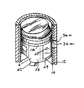
FIG. 1 shows one cylinder of a two cycle crankcase
compression internal combustion engine 2. A piston 4 is
reciprocal in a cylinder 6 between a crankcase 8 and a
combustion chamber 10. The cylinder is formed by a cylinder
block 12 having a cylinder liner 14. Piston 4 has one or
more rings 16 engaging cylinder liner 14. A carburetor 16
supplies fuel and


~,,,,LB .,,

329370

air as controlled by throttle valve 18 into crankcase 8
through one-way reed valve 20. The carburetor includes
a float bowl 22 with a float 24 having a lever 26
pivoted at 28 to open and close valve 30 to admit or
block fuel from the fuel pum?, as is conventional.
Combustion chamber 10 includes a fuel-air inlet port
32. A fuel-air transfer passage 34 extends between
crankcase 8 and fuel-air inlet port 32. Combustion
chamber 10 includes exhaust port means 36 provided by a
pair of openings 36a and 36b, FIG. 2, through cylinder
liner 14 aligned with a second pair of openings 36c and
36d, FIG. 5, through cylinder block 12. Exhaust bridge
means is provided by an exhaust bridge 38 between and
bridging openings 36a and 36b, and an exhaust bridge 39
between and bridging openings 36c and 36d. Piston 4 is
connected to crankshaft 40 by connecting rod 42.
In operation, piston 4 has a charging stroke
in the upward axial direction as shown at arrow 44
compressing fuel-air mixture in combustion chamber 10
and creating a vacuum in crankcase 8. Piston 4 has a
power stroke upon combustion of the mixture by spark
plug 46 driving piston 4 downwardly in the opposite
axial direction pressurizing crankcase 8 and forcing
fuel-air mixture to flow from crankcase 8 through
transfer passage 34 to fuel-air inlet port 32 in
combustion chamber 10 for repetition of the cycle. The
spent combustion products are exhausted through exhaust
port 36.
Cylinder liner 14 has an axially extending
portion 48, FIG. 4, along its outer surface 50 at
exhaust bridges 38 and 39 and spaced from cylinder
block 12 by a gap 52 defining an axially extending flow
passage communicating at its bottom axial end 54 with
crankcase 8 and at its top axial end 56 with exhaust
bridges 38 and 39. Gap 52 provides a fuel-air flow

-
~329370
passage from crankcase 8 to exhaust bridges 38 and 39
along the interface between cylinder liner 14 and
cylinder block 12. During the downward power stroke of
piston 4, fuel-air mixture in crankcase 8 is forced
upwardly through axially extending flow passage gap 52
to cool and lubricate exhaust bridge 38 and cool
exhaust bridge 39. Flow passage gap 52 is preferably
provided by an axially extending slot 48 in the outer
surface of cylinder liner 14. Alternatively, flow
passage gap 52 may be provided by an axially extending
slot in cylinder block 12. As seen in FIG. 5, flow
passage gap 52 extends axially along and between and
communicates with exhaust bridges 38 and 39. Flow
passage gap 52 does not communicate with openings 36a
15 and 36b, nor with openings 36c and 36d.
Piston 4 has a cylindrical outer side wall 58
of given radius closely adjacent cylinder liner 14
except for a relieved surface portion 60 extending
axially therealong and facing exhaust bridge 38 and
20 spaced from cylinder liner 14 by a gap 62 defining a
second axially extending flow passage. Flow passage
gap 62 has a top axial end closed by piston rings 16,
and has a lower axial end closed by a lower skirt
portion 64 of the piston side wall which is not
25 relieved and which has the noted given radius and is
closely adjacent cylinder liner 14. Surface 60 is
preferably machined flat.
Exhaust bridge 38 of cylinder liner 14 has a
plurality of apertures 65, 66, 67 and 68 drilled
30 radially therethrough communicating between flow
passage gaps 52 and 62. During the power stroke of the
piston, fuel-air mixture in crankcase a is forced
through flow passage gap 52 between cylinder liner 14
and cylinder block 12 and through apertures 65-68 of
35 exhaust bridge 38 and into flow passage gap 62 between

- s - 1329370

piston 4 and cylinder liner 14. This flow through
exhaust bridge 38 improves cooling and lubrication of
the latter. The flow leaks back into crankcase 8 along
the interface between cylinder liner 14 and piston side
wall 58 including lower portion 64. It is also
preferred that a one-way check valve 60 be provided in
flow passage gap 52 permitting fuel-air mixture flow
from crankcase 8 through flow passage gap 52 to exhaust
bridges 38 and 39, and blocking reverse fuel-air
mixture flow from exhaust bridges 38, 39 through flow
passage gap 52 to crankcase 8.

; L~


.. ... . . .. . . . .

Representative Drawing
A single figure which represents the drawing illustrating the invention.
Administrative Status

For a clearer understanding of the status of the application/patent presented on this page, the site Disclaimer , as well as the definitions for Patent , Administrative Status , Maintenance Fee  and Payment History  should be consulted.

Administrative Status

Title Date
Forecasted Issue Date 1994-05-10
(22) Filed 1988-12-14
(45) Issued 1994-05-10
Deemed Expired 2010-05-10

Abandonment History

There is no abandonment history.

Payment History

Fee Type Anniversary Year Due Date Amount Paid Paid Date
Application Fee $0.00 1988-12-14
Registration of a document - section 124 $0.00 1989-02-28
Maintenance Fee - Patent - Old Act 2 1996-05-10 $100.00 1996-04-15
Maintenance Fee - Patent - Old Act 3 1997-05-12 $100.00 1997-04-14
Maintenance Fee - Patent - Old Act 4 1998-05-11 $100.00 1998-04-06
Maintenance Fee - Patent - Old Act 5 1999-05-10 $150.00 1999-04-06
Maintenance Fee - Patent - Old Act 6 2000-05-10 $150.00 2000-04-04
Maintenance Fee - Patent - Old Act 7 2001-05-10 $150.00 2001-04-04
Maintenance Fee - Patent - Old Act 8 2002-05-10 $150.00 2002-04-03
Maintenance Fee - Patent - Old Act 9 2003-05-12 $150.00 2003-04-02
Maintenance Fee - Patent - Old Act 10 2004-05-10 $250.00 2004-04-06
Maintenance Fee - Patent - Old Act 11 2005-05-10 $250.00 2005-04-06
Maintenance Fee - Patent - Old Act 12 2006-05-10 $250.00 2006-04-05
Maintenance Fee - Patent - Old Act 13 2007-05-10 $250.00 2007-04-10
Maintenance Fee - Patent - Old Act 14 2008-05-12 $250.00 2008-04-07
Owners on Record

Note: Records showing the ownership history in alphabetical order.

Current Owners on Record
BRUNSWICK CORPORATION
Past Owners on Record
HUNDERTMARK, JAMES M.
Past Owners that do not appear in the "Owners on Record" listing will appear in other documentation within the application.
Documents

To view selected files, please enter reCAPTCHA code :


To view images, click a link in the Document Description column. To download the documents, select one or more checkboxes in the first column and then click the "Download Selected in PDF format (Zip Archive)" or the "Download Selected as Single PDF" button.

List of published and non-published patent-specific documents on the CPD .

If you have any difficulty accessing content, you can call the Client Service Centre at 1-866-997-1936 or send them an e-mail at CIPO Client Service Centre.


Document
Description 
Date
(yyyy-mm-dd) 
Number of pages   Size of Image (KB) 
Representative Drawing 2002-02-27 1 11
Drawings 1994-07-22 2 57
Claims 1994-07-22 5 173
Abstract 1994-07-22 1 16
Cover Page 1994-07-22 1 16
Description 1994-07-22 7 246
PCT Correspondence 1988-12-08 1 26
PCT Correspondence 1994-02-16 1 28
Prosecution Correspondence 1992-02-17 3 85
Examiner Requisition 1991-11-18 1 26
Prosecution Correspondence 1989-08-31 1 36
Fees 1997-04-14 1 70
Fees 1996-04-15 1 58