Note: Descriptions are shown in the official language in which they were submitted.
~329~39
:~,
MET~OD AN~ APPARA~US FOR DETECTING
AN OUT OF BEAM CO~DITION IN A ~ONOPULSE ~ADAR RECEIvER
BACRGROUND OF ln~ INVENTION
l. Field o~ the Invention
This invention relates generally to radar systems,
and mor~ particularly to the detection o~ an out o~ beam
condi~ion in a monopulae radar recelver.
2. D~cri~tl~g ~ rt
In a monopulse radar receiver, sum and di~erence
olgnals are ~ormed ~rom plural antenna beams. The dl~erence
~ignAl i~ repr-sontative Or the tracklng error, i.e., the
angle that the target being tracXed io of~ the boreslght
lln~ o~ the antenna and i8 thore~ore ufied ~or automatic
tracklng. In ~ome radar ~ystems, usually those ~mploying
a ~lngl- target tracX mode, a ~earch ~can operation precedes
the automatlc tracking mod~. A~ter target acqul~itlon,
the ~earch ~can ~odo 18 ~topped and tho antenna i9 trained
on the ta~get by the automatl¢ tracXing equipment. Other
radar ~y~tem~ mploy a "tracX while ~can" mode o~ operatlon,
ln which th- po-ltlon o~ one or more target~ i9 continually
txaok-d on th- basio o2 th- data received whil~ the antenna
al-o per~ormlng a ~earch can. It 18 necoogary that
:.', .
~' ' . .:
~32~3~
the equipment be able to detect when a target being
tracked is out of the beam of the antenna, so that the
track can be deleted, in a track while scan system, or
the target reacquired by switching to the scanning mode,
in a search and track radar.
Current techniques for detecting an out of beam
condition are based upon the signal to noise ratio of the
radar return signal and do not permit the direction of
the target from the boresight to be ascertained. Signal
to noise ratio i8 an ambiguous indicator of an out o~
beam condition. The signal to noise ratio may drop due
-- to other factors such as ground clutter, noise, jamming
or changes in atmospheric condition. To minimize the
likelihood of an ambiguity, the signal to noise ratio
must be monitored for a long time before a reliable out
of beam determination can be made.
SUMMARY OF THE INVENTION
Various a~pects o~ this invention are as follows:
2~ A method for detecting an out of beam condition in a
monopulse radar receiver comprising the steps of:
~orming sum and di~erence signala ~rom a target
return eignal;
combining the sum and difference signals to form a
~irst vector signature signal;
combining the eum and dif~erence signals to form a
~econd vector signature signal 80 that the phase
dir~erence between the ~irst and ~econd signature signals
varie~ with the amplitude o~ the di~erence eignal;
comparing the rir~t and ~econd eignature signals to
detect the pha~e dl~rerence therebetween;
comblning the sum and dif~erenco signal~ to ~orm a
thlrd vector signature eignal in which the di~rerence
signal i~ Or opposite pha~e to the dirrerence signal Or
the rirst ~ignature signal;
combining the sum and dir~erence ~ignal~ to ~orm a
~ourth vector ~ignature signal in which the di~rerence
B
~29~3~
2a
signal is of opposite phase to the difference signal of
the second signature signal, the phase difference between
the third and fourth signature sig~als varying with the
amplitude of the difference signal; and
comparing the third and fourth signature signals to
detect the phase difference therebetween.
A monopulse radar receiver comprising:
means for forming sum and difference signals from a
target return signal;
means for combining the sum and difference signals
in pha6e quadrature to form a first vector signature
_ signal;
means for combining the sum and difference signals
in phase quadrature to form a second vector signature
signal so that the phase difference between the first and
second ~ignature signals varies with the amplitude of the
di~erence signal;
means ~or comparing the first and second signature
signals to detect the phase di~ference therebetween;
mèans for combining the sum and difference signals
in phase quadrature to ~orm a third vector signature ~;
eignal in which the dirrerence signal is of opposite
pha~e to the di~erence signal o~ the ~irst signature
signal;
means for combining the sum and dif~erence ~ignals
in phase guadrature to form a ~ourth vector signature
~ignal in which the dir~erence ~ignal is Or apposite
phase to the di~erence signal o~ the second signature
signal, the phase dif~erence between the third and fourth
~ignature ~iqnal~ varying with the amplitude of the
difrerence signal; and
mean~ ~or comparing the third and fourth signature
~ignal~ to dstect the pha~e di~erence therebetween.
By way o~ added ~xplanation, according to an a~pect
3S o~ the invention, there are derived from the sum and
dl~rerenc~ ~lgnals o~ a monopulse radar receiver a pair
o~ ~ignature~ that quickly and reliably, i.e.,
unambiguously, indicates when a target being tracked
.~7 ' ~.,', .
132983~1 :
2b
moves out of the center of the antenna main beam.
Specifically, sum and difference signals are formed from
a target return signal. The sum and difference signals
are combined in phase quadrature to form a first vector
signature signal. ~he sum and difference signals are
also combined in phase quadrature to form a second vector --
signature signal so that the phase difference between the
signature signals varies with the amplitude of the
difference signal. The first and second signatures are
compared to detect the phase difference therebetween.
When the target is out of ~eam, this phase difference is
clo~e to a nearly constant value, i.e., +90. Within the ~-
center of the main beam, ~
~`~ ', ', .
'
-1~2~839
l this phase difference varies over a range of other values,
e.g. between -180- and 0 .
A ~eature of the invention is the use o~ commutated
~ignatures to determine the direction o~ target displace- - -
5 ment from the antenna boresight and/or to verify the accuracy -~
o~ the out o~ beam indication. Speci~ically, the phase
di~erence between the commutated signatures approaches
the constant value, i.e. +90-, ~rom one direction, ~.e.,
~rom +180-, on one side o~ the antenna boresight and from -~
the other direction, i.e, 0-, on the other side o~ the
borèsight. Thus, the direction o~ target displacement
~rom the bore~ight i~ determined by observing the direction
o~ approach o~ the phas~ di~erence to the +90- constant
value. Moreover, the phase di~erence between the signatures
and the pha~e di~erence bstween the commutated signatures
11~ on opposite ~ides o~ and are symmetrical about the
~constant value, i.e., +90- line.
- 30 ~
. .'.
~ .
3S
1329839
: ',
3a
A method for detecting an out o~ beam condition
in a monopulse radar receiver comprising the ste~s o~
Sorming sum and difference ~gnals ~rom a target
return signal;
5combining the sum and dlfrerence signals to Sorm
a ~lrst vector signature slgnal;
combining the sum and difSerence signals to ~orm
a second vector signature signal 50 that the phase diSference
between the signature signals varies with the amplitude o~
the di~erencQ slgnal; and
comparing the Sirst and second signature ~ignals
to dotect the phas0 dirSerence therebetween -~
A monopul~- radar rec-~v-r comprl~ing
mean~ ~or ~orming ~um and di~erence signals
15 rrom a target return signals ;~
~ean~ Sor comblnlng the ~um and dl~ference signals
~n pha~e guadratur~ to ~orm a Sir~t vector ~ignature signal;
m~ans Sor combin~ng tho ~um and diSrQrence ~ignal~
ln pha~- quadraturo to Sorm a ~econd vector signatur-
~gnal ~o that the pha~o dirSorance between the signature
~ignal~ ~arie~ with th- amplitudo oS tho diSSerence signal7 ~
and ~;
m~an~ ~or co~paring th~ rlr-t and ~econd signature
~lgnal~ to detect th- pha~e diSS-r-nco therebetween
. .
:' ;
,~
132~839 :
-4-
BRIEF DESCRIPTION OF THE DRAWINGS
The features of a specific em~odiment of the best :
mode contemplated of carrying out the invention are illus- -
trated in the drawings, in which:
5FIG. 1 is a diagram o~ the sum and di~erence signals
as a ~unction o~ angle-o~ antenna boresight;
FIG. 2 is a series o~ vector diagram~ illustrating
the signatures used by the invention at di~ferent angles
o~ boresight;
10FIG. 3 i9 a diagram of the phase di~ference between
the signatures used by the invention and the phase di~erence ~:
between the commutated signaturQs used by the invention:
FIG. 4 i~ a ~chematic diagram of apparatus for
practicing the invention; ::
15FIGS. 5 and 6 are diagram~ illu~trating the technique
~or determining the direction o~ target displacement o~ :
~~ore~ight; and
FIG. 7 i~ a ~low diagram o~ an algorlthm ~or determining
th- out o~ beam indication and the diraction o~ target .
displa¢em~nt o~ bore~ight.
,~
. - .
~: 30
..
~ 3~ .
,~ .
.:
:':
~L32~3~
-5-
1 DESCRIPTION OF THE PREFERRED EMBODIMENTS
In FIG. 1, the solid line depicts the absolute value
of the sum signal, ~ , as a function of angle-off-bore-
sight in milliradians (MR) and the dashed line represents
the absolute value of the difference signal, ~ , as a
function of angle-off-boresight in milliradians (MR). The
solid line also represents the relative gain characteristic
of the antenna. As depicted, the absolute value of the
difference signal is greater than the absolute value of
the sum signal in the antenna sidelobes associated with
the cardinal plane. The complex values of the sum and
di~ference signals are used to generate vector signatures
that are compared in phase to determine an out of beam
condition--speci~ically, a vector signature T1 =~+j~ and
lS a vector signature T2 '~
FIG. 2 illustrates vector signatures Tl and T2 for
'-8iX cases- In each case, at the top are represented the
sum and di~erence signals, in the middle are represented
the vector signatures including their phase relationship,
and at the bottom are represented the vector signatures
rotated with vector signature Tl as a common re~erence.
Case 1 i~ at the antenna boresight, the di~ference signal
approacho~ zero and the vector signatures which are each
comprised eolely Or the 5um signal, are -90- apart. Case
2 lllustrates how the vector signatures are constructed from
the sum and di~erence ~ignal~ by vector addition. Cases
2, 3 and 4 illustrate the vector signatures within the
maln beam of the antenna. Case~ 4, 5 and 6 illustrate the
~ vector ~lgnature~ out~lde the cent~r o~ the main beam; in
the~e ca~e5, the phase di~erence between the vector sign-
~- aturo~ i~ clo~e to 90- becau5e the di~erence slgnal is
.' . . . larger.than the s~m ~ignal ~much larger ~n casea~5 and 6~
It ~hould b- noted that the vector ~lgnatures compared
33 in pha~o to detormine an out o~ beam condition could be
~L 32~39
1 made up of other related combinations of the sum and diff-
erence signals, specifically the following:
1) Tl = ~ ; T2 a+i ~
2 ) T1 = -~ +jQ ; T2 = ~ j
3) T~ ; T2 ~ ~
In each case, the phase difference between the
sîgnatures Tl and T2, varies with the amplitude of the
di~ference signal vis-a-vis the sum signal. Since the
di~ference signal predominates over the sum signal in the
out of beam condition, a comparison o~ the signatures
yields a quick, reliable indication thereof. A drop in
the received signal due to the other factors such as
eclipslng arrects the signatures as well.
In FIG. 3, the solid line represents the phase
di~erence between vector signatures Tl = ~+j~ and
T2 ~ ~+i ~ as a ~unction of angle-o~f-boresight and the
-da3hed line represents the phase di~ference between the
commutated vector signatures Tl~3 ~ and T2'- - Q+j ~.
A~ depicted, both phase diS~erences swing about +90- outside
the center o~ the main beam on opposlte ~ides o~ the ~90
lino in symmetrlcal ~ashion. Within the center of the
main beam, both phaso di~erences vary ~rom 0 to -180-.
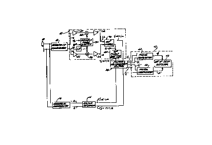
Re~erence i9 mado to FIG. 4 ~or apparatus to practice
the lnvention. An antenna 10 which is segmented ~or re-
ception purposes into two halves ~or each plane, i.e.,azlmuth and ol~vation, lntercepts a target return signal.
- Antenna 10 i0 pre~erably a two dimenslonal array having
~lotted element~ and a tapered radiation pattern. For
~impllclty, tho ~ollowing description only treats one
plane, l.e., azimuth. The sa~e procedure is ~ollowed with
r-~p-Gt to the other plane, i.e., elevation. Tho signal,-,a,~ s , interc-pted by ~n~enna l~ i0 proce~sed by-ldenb~oal- radaE
r-o~iv-r~ 12 and 14. Receiver 12 is doslgned to process a
~um ~lgnal, ~ , and a dl~erence 0ignal, - ~, recelved ~rom
3g a conv-ntional monopul~e comparator 16. Receivor 14 is
' ,: '
~ ~ ," .''"
1 329~39
,~
-7-
1 designed to process ~ sum signal, ~ , and a di~ference
signal, -~ , recei~ed from a conventional monopulse
comparator 18 Monopulse comparator 18 rotates the dif- -
~erence signal 180' (In practice, a single radar rece~ver
would be used in time multiplexed ~ash~on to process the
outputs Or both comparators 16 and 18 )
Receiver 1~ has an RF section comprising preampli~iers
20 and 22, mixers 24 and 26, a local oscillator 28 and a
variable phase shifter 30 and an IF section comprising
postampliYiers 32 and 34 and a 180 hybrid combiner 36
The di~erence signal ~rom monopulse comparator 16 i9
ampli~ied by preampli~ier 20 and beat down to IF in mixer
~4 by the pha~e shirted output of local o~cillator 28 The
IF output ~rom mixer 24 is ampli~ied by postamplirier 32 and
applied to hybrid combiner 36 Similarly, the sum signal
i~ ampli~ied by prea~plifier 22 and beat down to IF in
mixer-26 by the unphase-shi~ted output o~ local oscillator
28 The IF output ~rom mixer 26 is ampliried by postampl-
l~ier 34 and applied to hybrid combiner 36 Variable
pha~e shi~ter 30 is prererably electronlcally controllable
and programmed by means o~ a plurallty o~ inputs which
¢ontrol the pha~- o~ the output signals provided thereby
~ypically, the initial phase provided by pha~e shirter 30
matche~ the di~rersnt~al pha~e delay associat~d wlth the
~um and di~orence 6ignals ~rom monopulse comparator 16
Henoo, the pha~ di~erence between channel~ is zero degrees
The remainlng input o~ phaoe shl~ter 30 is chosen to apply
a 90' pha~e 6hi~t to the output o~ local o~cillator 28 used
to b-at down the dlr~erence ~ignal, thereby phase ~hi~tlng
the di~Ser-nc- ~ignal relatlv~ to the su~ signal The
hybrld combin-r produce- a~ one output ~ignal, th~ additive~ - combination o~ tn~ sig~alJ appli~d t~-r~to, ~h~n~ coupled~
to an analog ~llterlng and analog-to-dlgital conversion
~-ctlon 38 ~ybrld combinsr 36 produces as the other out-
put ~ignal, a ubtractlve comblnatlon o~ the signals applied
':'. " ,,
8 ~32.~33~
thereto, which is coupled through a 90 phase shifter 40 tosection 38 These are the output signals from receiver 12
representing ~ector f~ignatures Tt and T2 in analog form
Radar receiver 14 is identical to receiver 12 and uses a
local oscillator synchronized to oscillator 28 f(For further
details about the apparatus of FIG 4, reference is made to
Diamond Patent 4,568,940, which issued February 4, 1986 )
Because off the phase rotation of the difference 6ignal
produced by monopulse comparator 18, radar receiver 14
produceffffsfffff output signalff~fff representing the analog commfutated
vector ffff3ignatures T,' and T2', which arfe alfso coupled to
faffffffaction 38
The ffiltered, digital signature representative signals
produced by ffsfffffection 38 are coupled to a digital computer 42
Affffrfff depicted, computer 42 ie conffigured to ffunction as phaffee
comparators 44 and 46 and an out of' beam detector 48 Phase
cff~fparator 44 producee a signal representative of' the pha~e
diLffference f~f between vector fffffffffffignaturefefffff T~ and T2 Phafffff3e
¢omparator 46 produces a ~fffffignal rQprefffffentativfs of the phafffsffe
di~frerefnce f~fl between the com~utated vector eignatureffffffff Tl' and
T~ On the basls or these phaffffsfffe dirfference affffignalffffsfffff~ out ofbeam dfat-ctor 48 uffrffffffeffffffff three criteria deffffcribed below to
dotormlne when the target i8 out Or beam, and the direction off
dl~placfsfment rrom borelfffffffffffight.
2~ In FIG 5A, a point SO repref~ffffentffffff~ the antenna, a solid
llne 52 repreffsfffffentfffffffff thfe borelfffffffight off the antenna main beam, and
a taf~ffffhet line 54 represfffffffffentffffffff the point where ~ff and ~ signalffffffffff
ar- Iffffgual in magnitude A daff3hed line 56 represents the null
bfQtwef~ffffn th- main lobe and the ffirffffft Bidelobe, a dashed line 58
r-pref-efnt- the null between tho ffirfffffffffffft frfffffffidelobe and the ffffffffffecond
~d-lob-, and a ~olid line 60 repref-efntffffffff a targfeft path
r-L~tive to the ant-nna radiation pattern af~fff a ffunction off . ~,.
tim- In FIG 5B, the flffolid line
1329839
1 represents the phase difference ~ , between signatures ~1
and T2 as a function of time and the dashed line represents
the phase difference ~ between commutated signatures T~
and T2' as a function of time for the target path illustrated
in FIG. SA. As illustrated, while the target moves within
the center of the main beam from one side of the boresight
to the other, the phase differences ~ , and ~ also swing
back and ~orth about -90. When the target moYes out of
the center o~ the main beam, as depicted at point 61 in
FIG. 5A, phase di~ference ~ , passes through zero degrees
on the way to +90~, and swings about this value. Similarly,
phase di~erence ~', passes through +180- on the way to
~90- and then swings about this value. In FIG. ~A, the
target continue~ to move away ~rom the boresight, crossing
into the ~delobe at points 62 and 63. Points 62 and 63
are also represented in FIG. 5B.
~ ~o yield a valid indication o2 an out o~ beam condition,
the phase di~erences ~ , ~', should meet the ~ollowing
criteria:
(1~ Be close to +90-;
~2) Lie on opposite sides o~ +90~;
~3) Exhibit symmetry about l90-.
I~ these three te~ts are not met, either the target is not
out Or beam or the return ~ignal strength i5 too weak to
determine whether or not the target is out of beam.
A~ ~hown in FIG. 5B, the phase di~erences meet all
th~ee criteria betwsen points 61 and 62, between points 62
and 63, and between points 63 and 64, thus the target is
out o~ beam. Within the center o~ the main beam, i.e., to
;30 the le~t o~ point 6~ in FIG. 5B, the phase dir~erences
- ~ail th- ~irst criterion, namely that they lie close to
the con~ta~t~angl~, i.e. ~90'. Between poin~s 64~and
the phase di~-rences ~ail the second criterion, namely
that they lie on oppo~ite 6ides o~ the constant angle,
l.-. 190'. To the right o~ point 65, the phase dl~erences
1329~39
--10--
1 ~ail the third criterion, namely that they be symmetrical
about the constant angle, i.e. +so . In the latter two
case~, the signal is too weak to provide a valid indication
of the target position relative to the beam.
First and ~econd countera, not shown, in detector 48
are incremented and decremented in response to the phase
difrerence signals. Speci~ically, whlle the above criteria
are being met, either the ~irst counter or the second
counter, but not both, is incremented depending upon which
phase dir~erence signal is larger. The ~ir~t counter is
incre~ented when di~erence ~ignal ~ i~ larger, and the
second counter i8 incremented when difference signal ~'
is largex; both counters are decremented when any one o~ the
criteria i~ not met. As illustrated, the second counter
begins to count be~oro the first counter because phase
di~erence ~l lg larger than pha3e di~erence ~ between
polnt~- 61 and 62.
U~ing the same re~erence numerals as FI~. 5A, FIG. 6A
roprosent~ the antonna pattern and the target moving out
o~ beam ln the oppo~ite directlon. As lllu~trated ln FIG.
6~, in this case the situation ia reversed when the target
moves out Or tho center Or the maln beam as repre~ented at
point 66. Speolrlcally, phaao di~erence signal ~' passes
through zero degree~ on tho way to +90- and ~hase dl~ference
2S ~ pa~oe~ through -180- on the way to +90-. As deplcted
ln FIG 6C, in thi~ ¢ase the ~irst counter begins to count
b~ore tho ~econd countor, becauae phase di~erenc~ ~ ls
larg~r than phase dirreren¢e ~' between polnts 66 and
67, and tho ~ocond counter count~ between polnts 67 and
68.
~ comparl~on Or FI~S. S and 6 lllustratos how detector
~~ 48 d-tormine~ when ~-va~id out o~ boam con*itlon ha~ be*n
lndlcated and the directlon o~ tho target vi~-a-vls the
~or-~lght. An lncr-a-lng total count ln the rir8t and
3~ ~-¢ond countora lndl¢ate~ that tho target ls out of beam7
,....
''.''"',' '.
:
~32~83~
..
--11--
1 a decreasing total count indicates either that the target
is in the center of the main beam or the returned signal
strength is too weak to give a reliable indication o~ ~he
target location vis-a-vis the main beam. I~ the target is
out of beam, as indicated by an increasing total count,
the target is on one side o~ the bore3ight when the ~irst
counter starts ~ncrementing be~ore the second counter and
is on the other side o~ the boresight when the second
counter begins incrementing be~ore the first counter.
FIG. 7 is a ~low diagram o~ the algorithm $or
controlling the ~irst and second counters. This algorithm
can be i~plemented by a computer program in a straightforward
manner by one Or ordinary sXill using well known programming
techniques. Block 70 represents the phase di~erences.
lS Block 72 represents the ~ir5t criterion -- whether or not
both pha~e dir~erences are close to tha constant angle,
-i.o. ~90-. Kl i~ the value o~ a predetermined thresXold
wlthin which the criterion i5 deemed to be met, pro~erably
o~ the order o~ 10-. I~ this critsrion ls not met, both
counter~ are decremented a~ repre~ented by a block 84. I~
thlo crlterion 1~ met, then the phase di~erences are tested
~or tho ~ocond cr~terlon. As represented by block 74, in
thi~ crlterlon the phase dl~rerences ~rom +90- are examlned
to dotermlne i~ the sign~ aro oqual. I~ they are equal, the
oe¢ond critorion, pha~e dir~erence~ lylng on opposite
~ld~ o~ +90- i~ not ~ot and both counter~ are again decre-
m-nted. I~ the pha~e dir~erence~ havo opposito ~igns,
thon they aro examin~d ~or tho thlrd critorion. As repre-
~-ntad by block 76, tho thlrd crlt-rion 1~ met lr the ~um
o~ th- pha~o di~renco~ varie~ ~rom 180' by less than the
valu- o~ ~ predotermined thro~hold X2. This ~ean~ that
- t~- pha~ d~oronceo-aro symmetrical about ~90~ to wi~hin
tho thro~hold. I~ tho pha~o dl~ronce~ ~il thi~ test,
both countor~ aro decr-mentod. Otherwl~o, the~o phase
3~ dl~or-nc-~ ar- comparod to dotormine whlch is larger as
.,",'," "!~,"
132~8~
-12-
1 represented by block 78. If phase difference ~ is larger
than phase difference ~ ' , then the first counter is
incremented as represented by block 80; if the opposite,
then the second counter is incr2msnted as represented by
bloc~ 82.
In the described manner, the invention permits a
quick and reliable d~termination o~ when a target being
tracked i5 out o~ beam and the direction o~ the targQt
vis-a-vis the bore~ight.
The described embodiment of the invention is only
considered to be pre~erred and illustrative o~ the inventive
concept; the scope o~ the invention is not to be restricted
to such embodiment. Various and numerous other arrangements
may b~ devised by one skilled in the art without departing
~rom the spirit and scope o~ this lnvention. For example,
i~ Xnowledge o~ the direction o~ the out o~ beam target
-vi~-a-vl~ the boresight i~ not required, then it is not
nece~ary to generate the commutated signatures. Further,
a~ indlcated above, both normal and commutated 6ignatures
could be generated with the ~ame receiver employing time
multiplexing tQchniques rather than with separate recelvers,
as di~closed. Moreover, dir~erent ~ignatures than t~ose
disclosed could be employed, such as, ~or example, a) ~1 3
+~ 2 ~ r b) Tl - ~ + ~ ; T2 ' ~ ~ ~
In both Or these ca~es, the phase dir~erence between ~igna-
ture~ also varies wlth th~ amplitude Or the dif~erence
~lgnal, vls-a-vl~ the ~um ~ignal, being close to 0- in the
maln beam an~ clo~e to 180- outJide the maln beam. Further,
although it i~ pre~erred to omploy out o~ beam detector
48, the ~ha~- di~erence~ could be evaluated by a human
op-rator ob~orving a di~play Or ths ~hase di~rerence~,
. whlch i~ ~drL~en.~ ha~e comparator~ 44 and 46. ~n such
ca~e, the pattern~, de~lcted in FIGS. 5B and 6~ would in
e~onco appear on the dl~play rOr evaluation by tho operator.
3~
''.