Note: Descriptions are shown in the official language in which they were submitted.
:
133~38~
C-4040
G-1550
COUNTERGRAVITY CASTING APPARATUS
This invention relates to apparatus or the
vacuum, countergravity casting of metal in
gas-permeable, shell-type molds immersed in a pot of
molten metal and, more particularly, to means for
mounting the mold to the vacuum chamber so as to:
eliminate the nee~ to ~dhesively bond the mold portions
(i.e., cope, drag, cheeks, etc.) together; resist
destructive flexure of the mold during the application
of the casting vacuum; and/or eliminate stress
concentration sites and provide a substantially uniform
seal between the mold and the vacuum chamber.
Background of the Invention
~.
The mold-immersion-type, vacuum, .
countergravity, shell mold casting process is
particularly useful in the making of thin-walled,
near-net-shape castings and involves: sealing a -~ :
bottom-gated mold, having a gas-permeable upper
portion, to the mouth of a vacuum chamber such that the
20 chamber confronts the upper portion; immersing the ::
underside of the mold in an underlying melt; and
evacuating the chamber to draw melt up into the mold ~ :
through one or more of the gates in the underside
thereof. Such a process is shown in U.S. patent
4,340,108, issued July 20, 1982, in the names of George
D. Chandley and Richard L. Sharkey, wherein the mold
comprises a resin-bonded-sand shell having an upper : ~:
cope portion and a lower drag portion sealingly mounted
to the mouth of the vacuum chamber by means of spring
clips. U.S. patent 4,340,108 seals the mold to the
. vacuum chamber atop the cope such that the parting line
: -: :
~L3~03~
between the mald halves lies cutside the vacuum
chamber. U.S. patent 4,632,171, issued December 30, ~;;
1986, in the name of Roger L. Almond and assigned to
the assignee of this invention, seals the mold to the
mouth of the vacuum chamber atop the drag such that the
parting line between the cope and drag falls within the
vacuum chamber. U.S. patent 4,658,880, issued ~pril
21, 1987, in the name of Karl D. Voss and assigned to
the assignee of this invention, mounts the mold to the
vacuum chamber by means of a plurality of reciprocable
and rotatable shafts having self-tapping threads on the ;
lower ends thereof engaging mounting sites atop the
mold. Chandley, G. D. Automatic Countergravit~ Casting ~ ~ ~
15 of Shell Molds, Modern Casting, October 1983, pag~s ;~ `
29-31, mounts round molds to a round vacuum chamber
having self-tapping threads which screw into the
periphery of the mold.
The aforesaid references all disclose rigid `
vacuum boxes and molds whose upper and lower halves are
glued together. The gluing process is expensive and
time consuming and elimination thereof would improve
the efficiency and economics of the process. Moreover,
when the aforesaid mold-chamber arrangements are used
25 with molds having more than about 400 square inches of ~`
mold confronting the vacuum chamber, there is a
tendency for the molds to bow or flex into the chamber
X(;
~
~;; .~ '.:.`.
~L3~3~
when the casting vacuum is drawn therein unless they
are made extra strong/thick. This flexure can destroy
the mold either by cracking or fracturing the mold or
occasionally causing implosion thereof into the
chamber.
Two techniques or eliminating gluing the mold
portions together and reducing undesirable inward
flexure of the mold are the subject of u.S~ patent
4,809,767, issued March 7, 1989, in the names of Karl
D. Voss et al and assigned to the assignee of this `
application. These techniques provide substantially
rigid means for pressing the mold portions together and -
resisting inward flexure of the mold. Such structures,
15 however, do not accommodate process variations well. ~`
Hence variations in mold dimensions or untrue mating of
the mold with the vacuum chamber can result in improper
engagement between the mold and vacuum chamber and/or
the creation of stress concentration sites which can ~ ~`
20 cause cracking/fracture of the mold. Moreover, on an `
automated basis systems such as described in U.S.
patent 4,809,767 (supra) require additional means for
locating the pressers and controlling the amount of
force applied thereby to prevent damagc to the molds or
dislodgment thereof from the mouth of the vacuum
chamber. It would be desirable to eliminate such ~`
extraneous locating and control means and otherwise
provide apparatus more tolerant of process variations.
It is the principal object of the present
invention to provide an improved simple, self-adjusting
apparatus for the vacuum, countergravity casting of ; ;
3 -~
:.
L
1 330386
unglued shell mold portions including means for
resiliently biasing the upper mold portion into sealing -~
engagement with the lower mold portion, resisting
destructive flexure of the mold during casting and
avoiding the creation of stress concentration sites in
the assembly. This and other objects and advantages of
the present invention will become more readily apparent
from the detailed description thereof which follows.
~rief Description of the Invention
lOThe presen~ invention contemplates
mold-immersion-type countergravity casting apparatus of
the type described above including spring means
resiliently pressing the mold portions (i.e., cope,
drag, cheeks) sealingly together (i.e., sans adhesive).
When large area molds are used, the spring means
functions to resist destructive inward flexure o~ the
molds when the casting vacuum is drawn in the vacuum
chamber, which function is served whether the mold
parts are glued or not. More specifically, apparatus ~;
in accordance with the present invention includes: a
mold which is adapted for immersion into an underlying
pot of molten metal and which comprises a porous,
gas-permeable, upper shell and a bottom-gated lower
portion; a vacuum box defining a vacuum chamber
confronting the upper shell for evacuating the mold
through the shell, which box comprises (1) a ceiling
overlying the mold, and (2) a skirt depending ~rom the
ceiling and surrounding the shell, which skirt has a
peripheral edge on the underside thereof sealingly
30 engaging the mold; means for mounting the mold in the ;~;
mouth of the vacuum chamber; and spring means
' ~.
~330~8~
resiliently pressing the shell into sealing engagement
with the lower mold portion and/or resisting
destructive inward flexure of the mold when a vacuum is
drawn in the vacuum box. The spring means provides the
vacuum box with self adjustability to compensate for
process variations (e.g., variations in mold dimensions
from one to the next) and will preferably be secured to --
a removable plate affixed to the inside of the chamber
to minimize the number of possible vacuum leak sites.
The vacuum box will preferably include a
two-part skirt, i.e., a skirt which is horizontally
split into an upper fixed portion carried by the ~
mold/chamber transfer mechanism and a self-truing, ~ -
lower, floating portion. The upper and lower skirt
portions are separated one from the other by a narrow
(e.g., about 5/16 inch) gap which permits to and fro
movement of the upper and lower portions relative to
each other. Spring-containing retainers couple the
upper and lower skirt portions together and serve to
20 press the mold-sealing edge of the lower skirt portion ;
down onto the mold so as to eliminate the creation of
stress concentration sites (i.e., high pressure points)
and provide a substantially even/uniform pressure on
the peripheral ~eal between the mold and lower skirt.
25 Detailed Description of Specific Embodiments ;~
The invention may better be understood when
considered in the light of the following detailed
description of certain specific embodiments thereof
which is given hereafter in conjunction with the
several drawings in which~
Figure 1 is a partially sectioned, elevational
1~3~3~
view of one em~odiment of a countergravity casting
apparatus according to the present invention;
Figure 2 is a partially sectioned elevational
view of another embodiment of a countergravity casting ~ `
5 apparatus according to the present invention; ~ .
Figure 3 is a partially ~ectioned eleva~ional
view of still another embodiment of a countergravity
casting apparatu~ according to the present invention; : :
Figure 4 is a view in the direction 4-4 of
Figure 3;
Figure 5 is a partially sectioned elevational
view of still another embodiment of a countergravity ~:
casting apparatus according to the present invention;
Figure 6 is a view in the direction 6-6 of ~ ~ .
Figure 5;
Figure 7 is an enlar~ement of a portion of the
vacuum chamber of Figure 3;
Figure 8 is an enlargement of the seal .
clamping bar of Figure 7; and
.
Figure 9 is a portion of a vacuum chamber like
that of Figure 3 showing a preferred embodiment of the
cope biasing spring. :~
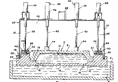
Figure 1 depicts a pot 2 of metal melt 4 which
is to be drawn up into a mold 6 comprising a
gas-permeable upper shell portion 8 and a lower portion
10 joined at a parting line 12 and defining a molding
cavity 14 therebetween. The lower portion 10 includes ::
a plurality of ingates 16 in the underside thereof for
admitting melt 4 to the mold cavity 14 when it is
evacuated through the shell 8. The lower portion 10 of
the mold 6 is seaied to the mouth 18 of a vacuum
':
133~3~6
chamber 20 (i.e., defined by vacuum box 22) via a
compressible seal 24 (e.g., high temperature rubber,
ceramic rope, etc.) affixed to the lower peripheral
edge of the depending skirt 21 of the box 22. The
vacuum chamber 20 encompasses the upper portion 8 of
the mold 6 and communicates with a vacuum source (not
shown) via conduit 26. The upper portion 8 of the mold
6 comprises a gas-permeable material (e.g.,
resin-bonded sand, ceramic, etc.) which permits gases
to be withdrawn from the casting cavity 14 therethrough
when a vacuum is drawn in the chamber 20. The lower
mold portion 10 of the mold 6 may conveniently comprise ~ ~;
the same material as the upper mold portion 8 or other
materials, permeable or impermeable, which are
compatible with the upper portion material. The lower ~ "
mold portion 10 includes an upstanding levee 26
surrounding the seal 24 and isolating it from the melt `~
4 as described in U.S. patent 4,745,962, issued May 24,
1988, in the names of James B. Mercer and Karl D. Voss
and assigned to the assignee of the present invention.
The lower mold portion 10 includes a plurality of
anchoring sites 28 engaged by T-bar keepers 30. The lower ~'i
portion 10 of the mold 6 includes a plurality of anchoring
cavities 32 adapted to receive T-bar keepers 30 via slots 34
in the shelves 40 overlying the anchoring cavity 32. A 90 ``
rotation of the T-bar carrying shafts 36 (e.g., by
~ 33a3g~ :
air motors 38) cause the T-bar keepers 30 to engage the
underside of the shelves 40 overhanging the cavities 30
to secure the mold to the box 22. Other mounting means
such as disclosed in the other references (supra)
would, of course, also be acceptable.
The upper shell portion 8 is pressed into ~ ;
sealing engagement with the lower mold portion 10
~i.e., at the parting line 12) by means of a plurality
of plungers 42. Feet 44 on the ends of the plungers 42
distribute the force of the plungers 42 more widely
across the top of the shell 8 to prevent
penetration/puncture thereof by the ends of the
plungers 42. Pneumatic springs 46 bias the plungers 42
downwardly to resiliently press the shell portion 8
against the lower mold portion 10 as the mold 6 is
being positioned in the mouth 18 of the box 22.
Schrader valves 48 on the air springs 46 permit varying
the pressure in the springs 46 as needed to app}y
sufficient force to press the upper portion 8 into ;~
sealing engagement with the lower portion 10, and, as
needed, to prevent destructive inward flexure of the
mold 6 when the casting vacuum is drawn. The force
applied by the plungers 42, however, will not be so ;~
great as to overpower and damage the anchoring 6ites
28, dislodge the mold 6 from the mouth 18 of the box
22, or break the seal formed thereat.
In accordance with another embodiment of the
present invention, Figure 2 depicts a countergravity
casting apparatus similar to that of Fiqure 1 but
differing therefrom with respect to the nature of the
spring means used to press the upper shell 8 ag~inst
.. , ,~ .
.
: .
~03~
the lower mold portion 10. The structural elements of
the apparatus of Figure 2 which are common to the
structural elements of the apparatus of Figure 1 have
the same numerical designation. The apparatus of
Figure 2 differs from that of Figure 1 in that the
vacuum box 22 has a removable ceiling 50 which permits
ready changeover from one size vacuum box to ~he next
by merely bolting on differently dimensioned s~irts 21.
Moreover, the separable ceiling 50 provides topside
access to the vacuum chamber 20 for removal of carrier
plate 52 used to support and carry the spring means 54
totally within the confines of the box 22. More
specifically, the carrier plate 52 is bolted at ear~ 56 -~
welded to the inside of the skirt 21 of the box 22.
The plate 52 may include apertures 58, as necessary, to
insure that the entire chamber 20, on both sides of the
plate 52, is maintained at substantially the same
sub-atmospheric pressure during casting and to permit
gasses generated during the molding to exhaust from the
chamber 20 via the conduit 26. In this embodiment, the
spring means 54 comprises a shaft 59 within a coil
spring 68 and having a head 60 on the upper end thereof
and external threads 62 on the lower end thereof. The
shaft 59 slides through an opening 64 in the plate 52
with the head 60 serving as a stop to prevent the shaft
59 from falling or being pushed out of the opening 64.
A foot 66 having internal threads (not shown) is
screwed onto the threads 62 and may be used to fine
tune the length of the shaft 59 and force exerted by
the coil spring 68 compressed between the foot 66 and
the underside of the plate 52 as shown.
9 :~
'"~' . '-: . .'.
~33~3~
~
Before the mold 6 is assembled to the box 22, ~-
the spring means 54 will hang from the plate 52 by
engagement of the head 60 therewith. When the mold ~
is positioned in the mouth 18 of the box 22, the upper
portion 8 pushes up on the lower end of the spring
means 54 (i.e., collar 66) causing compression of the
coil springs 68 and upward unseating of the head 60
from the top of the plate 52. In this position, the
compressed springs 68 push back on the upper mold
member 8 with sufficient force to cause it to seat and
seal atop the lower mold member 10 and to resist the
tendency of the mold 6 to flex or bow inwardly when a -
vacuum is drawn in the chamber 20. The force supplied
by the spring 68 will, however, not be so great as to
break the mounting sites 28, disrupt the seal formed at
the mouth 13 of the box 22 or otherwise dislodge the
mold 6 from the box 22.
The embodiments shown in Figures 3 and 4 are
similar to that shown in Figure 2 but contain
additional features described hereafter relating to
another important and preferred feature of the `
invention. More specifically, the skirt depending from
the ceiling 50 of the vacuum box 22 is horizontally
separated into an upper skirt portion 70 and a lower
skirt portion 72 separated one from the other by a gap
74. The qap 74 will typically be about 5/16 inch wide.
As best shown in Figure 7, a two inch wide flexible
sealing member 76 coextensive with the gap 74 is
secured to the upper and lower skirt portions 70 and
72, respectively, so as to cover the gap 74 and thereby
maintain the integrity of the vacuum chamber 20 when ` ~
~' "
.,' .' '," ' ::
~3~3~
the vacuum is drawn therein yet permit the lower skirt
portion 72 to float sufficiently to level or true
itself with respect to the mold 6 even when the
horizontal plane of the mold is not perfectly parallel
s to the sealing edge of the vacuum box 22. The flexible ~-
seal 76 comprises a 0.60 inch thick gas impermeable
Fiberglas-filled silicone rubber material commonly used
for conveyor belts and provided by the F. B. Wright Co.
as Material No. GP 207-100-MC-2-108. This seal
material was found to be particularly effective in
resisting inward ballooning and rupturing when the
vacuum is drawn in the chamber yet still be flexi~le
enough for the intended purpose. The seal 76 is
attached to the upper and lower skirt portions 70 and
72, respectively, by a pair of continuous bar clamps 77
bolted to the upper and lower skirt portions at a
plurality of locations. AS best shown in Figure ~, the
bar clampis 77 each include a base portion 79 for
bolting to the skirt and a leg portion 81 extending
from the base portion 79 to define a continuous recess
83 therebetween for engaging and pressing the seal 76
tightly against the inside wall of the skirt. The
inside face 85 of the leg 81 lies at an acute angle
(preferably about 85) to the ~ace 87 of the base 79 to
provide a sharp edge 89 which bites into the seal 76 to
firmly hold the seal 76 in place. ~ sheet metal shield
78 i~ secured along its bottom edge 80 to the lower
skirt portion 72 and extends upwardly and over the seal
76 to protect it from physical and/or thermal damage
30 (e.g., metal spatter). The upper edge 82 of the shield ~ -
78 is unattached and is free to slide along the inside
11 '"''~'
:~: . :.
'`"''"';~.`',''~"
~ 3 3 ~
12
surface of the upper skirt portion 70 as the gap 74
opens and closes in the manner described hereina~ter.
The upper and lower skirt portions 70 and 72, "~
respectively, are held together by a retaining means 84
which permits the lower portion 72 to float somewhat
independently of the upper portion yet prevents it from
so separating from the upper portion 70 as to damage
the seal 76. More specifically, the retainer means 84
includes an upper bracket 86 secured (e.g., welded) to
the upper skirt member 70 and a lower bracket 88 welded
to the lower skirt portion 72. A bolt 90 extends
loosely through the brackets 86 and 88 so as to permit
relative movement between the bolt and the brackets. .~ "
- coil compression spring 92 surrounds the bolt 90. The
combination of the gap 74, retainer means 84 and
flexible seal 76 permits the lower skirt portion 72 to ~`
float relative to the upper skirt portions 70 to better ~ ~
receive the mold 6 without damaging it such as could ~ ;
occur if pressure points or stress sites were otherwise
created. The springs 92 press the lower skirt portion
72 down against the sealing surface 94 atop the lower
mold portion 10 so as to provide a substantially
uniform sealing pr~ssure therebetween regardless of any
unlevel or unplumb condition existing between the mold
6 and the box 22.
In the embodiment shown in Figures 3 and 4,
the mold 6 is ~upported on hangers 96 having L-shaped
hooks 98 which carry the mold 6 ~rom a loading station
to the casting station shown in Figure 3. In
operation, the mold 6 is first placed on the hangers 96
(i.e., at the loàding station) and the vacuum box 22
: . :::
12
~ 3 ~
13 ~ '~
lowered to engage a stop located such that the lower
skirt portion 72 touches/engages the mold 6 with
substantially no compression of the springs 68 or 90.
The thusly mated mold 6 and box 22 are then trans~erred
to the casting station and immersed in the melt 4. At
that time, the buoyant forces of the melt cause the .'
mold 6 to float off of the hooks 98, narrow the gap 74,
and compress the springs 68 and 90 until equilibrium is
established. Finally, when the vacuum is drawn in the
chamber 20, the mold 6 is drawn further off the hooks
98 and up into the box 22 further closing the gap 74
and compressing the springs 68 and 90. The unique
features of this, the preferred embodiment of
Applicant~s invention, provide a self-adjusting system
which accommodates wide process variations without
stressing the molds to the point of breakage.
Figures 5 and 6 depict still another
embodiment of Applicant~s invention and, more
specifically, show a mold 100 having an upper portion
102 resiliently pressed against a lower portion 104 by
means of coil springs 106 surrounding the shaft 108 ~''; '
used to carry the T-bar keepers 110. In this regard, a ; '
washer 112 adapted to slide axially along the shaft 108 '-~
engages the top surPace of the upper portion 102 ''~
surrounding the slot 114 in the upper portion 102 ": '~
through which the T-bar keepers 110 pa~ses to access '~
the anchoring cavity 116 formed in the lower mold
portion 104. In operation (i.e., at the loading -~
station) the vacuum box 22 descends upon the mold 100
30 until the seals 24 seal'ingly engage the upper surface '-''~
of the lower mold portion 104. Thereafter, an air ~ ;
13
.
133~3~ :
cylinder 118 lowers the T-bar locking mechanism through
the slots 114 until the T-bar keepers 110 are fully
within the anchoring cavities 116. At that time, air
motors 120 rotate the T-bar keepers to secure the mold
in the manner described in United States Serial No.
147,963 supra. At the same time, the upper surface of
the upper mold portion 102 engages the washer 112
forcing it upwardly along the shaft 108 and compressing `
the springs 106 which resiliently press the upper
portion 102 down against the lower mold portion 104.
Figure g depicts a preferred embodiment of
spring biased plunger pressing the cope to the drag.
In this embodiment the spring retainer plate is spaced ~
from the roof of the vacuum chamber by a plurality of -`
spacers 126 and the plunger shat 128 passes
therethrough as described above in conjunction with
Figure 3. In this embodiment, however, the shaft 128
includes longer threads 130 on the lower end thereof
for receiving a threaded spring compression adjusting
collar 132 as well as a threaded foot 134 so as to
provide independent adjustment of the spring
compression and the shaft length as may be needed for
fine tuning the system.
While the invention has been disclosed -`
25 primarily in terms of specific embodiments thereof it --
is not intended to be limited thereto but rather only
:
to the extent set forth hereafter in the claims which
~ollows.
,~' .~' ' '." '
14
: ~,
.