Note: Descriptions are shown in the official language in which they were submitted.
`- ~ 330829
48565-2
METAL MEASURING METHOD AND APPARATUS
This invention relates to nondestructive testing of
metallic materials and, in particular, to the
measurement of properties of such materials using the
application of a high frequency alternating current to a
coil and measuring the change in inductive resistance of
the coil.
It i6 desirable to measure the physical and chemical
properties of metallic materials in order to ensure that
such materials meet specifications to which they have
been designed~ In galvanizing steel wire, for example,
it is desirable to ensure that the amount of the
galvanizing material used to coat the wire is correct
both for economic and operating reasons.
Galvanizing a wire comprises pulling the annealed
and acid pickled wire through a bath of molten zinc and
drawing the wire upward through a wiper to remove the
excess zinc coating. To change the amount of coating,
one can vary the speed at which the wire is drawn through
the bath or the amount of wiping.
The measurement of the zinc coating is accomplished
by removing samples of wire from the beginning and the
end of the wire which was coated. The samples are then
submitted to "gravimetric testing" wherein they are
initially weighed and subsequently immersed in
hydrochloric acid to remove the zinc coating. The
samples are again weighed to determine the difference
and, hence, the weight of the coating~ Such results,
while determining with some accuracy the weight of the
zinc on the sample pieces, are slowly obtained and the
sample pieces are only indicative of the amount of
coating on the wire as a whole. Furthermore, it is a
relatively expensive process. ~
.~ .
,.,; , .... ..
---`` 1330829
~ 2 --
Other techniques have also been used to measure
coatings. One such technique is disclosed in U.S. Patent
4,593,244 to Summerq et al. This technique uses the so
called "skin effect" to measure the amount of coating on
a substrate. The aforementioned skin effect is so named
because when a frequency is applied to a metallic
substance, the magnetic flux is principally restricted to
the outer portion of the body and a less permeable
coating is more deeply penetrated than a more permeable
substrate. Thus, if an oscillator driven sensor coil has
a coated substrate positioned within the coil, the
impedance will be different from its value when an
uncoated substrate is placed within the coil. The use of
the coating "hides" the substrate since the coating will
affect the coil's impedance more than the substrate.
Thus, the characteristicæ of the coating are indicated by
the change in coil impedance which is readily measured.
In such a process, the oscillator frequency applied
to the coil is important to the sensitivity of the
instrument. While it is believed the explanations given
throughout this application correctly explain the
phenomena, such explanations are given in the interest of
full and complete disclosure and applicant would not wish
to be bound by the explanations if, subsequently, the
explanations are found to be incorrect or partially so or
if further explanations more accurately define the
phenomena which are not presently known to the applicant~
'~3
",
133082~
-- 3 --
There are two competing frequency dependant
parameter8 to conqider as follows:
5~ a rll(1)
SKIN DEPTH L f ~
10 R a ~f ~; 7 kHz < f < 5 MHz
COIL & SAMPLE CORE
A8 given above in ( 1 ), the first parameter that
govern8 impedance sensitivity is the skin depth. The
skin depth measured varie8 with the reciprocal of the
square root of the frequency. Thu8, in terms of 8kin
depth criteria, the ideal applied frequency would produce
a skin depth as deep as the coating at its thickest
point. If a 8hallower ækin depth were chosen, the
instrument would "miss" part of the coating 50 that,
essentially, the skin depth sets an upper limit on
measurable coating thickness. If a deeper skin depth
were chosen, an unnece8sary amount of the sub8trate would
be "seen" by the in8trument and the coating mea8urement
would become over8hadowed by the spuriou8 effects of the
8ub8trate. Thu8, the skin depth criterion affects
sensitivity in two ways. Fir~t, it sets the maximum
measurable coating thickness and, second, it determines
the amount of overshadowing from the substrate.
As given above in (2), the second parameter that
governs sensitivity is the extent to which the coil
resistance varies with the amount of the inserted sample
coating. A large variation in resistance i8 ea8y to
measure and leads to a 8ensitive instrument. The
re8i8tance of the coil and sample core combination
increases with the square root of frequency. At least to
~ ::
~!' ;;, , :
` 1330~29
- 4 -
the frequency upper limit of relation (2), inareasing
frequency increa~es the spread of the resi~tances
produced by sample cores with varying amounts of coating.
Thus, the resistance criterion also affects sensitivity
in two ways. First, it sets the minimum measurable
amount of coating and, second, it sets the minimum
measurable change in amount of coating.
There i9~ in addition, a further important factor in
the measurement system, namely the resonant frequency of
the sensor coil and associated capacitance. Signals are
strongest at resonance and thus for greatest sensitivity,
a coil and capacitance should be used which has a
resonant frequency at the oscillator frequency that was
chosen by utilizing the criteria of relations (1) and
(2).
The principle shortcomings of the previous attempts
have been the complexity of the circuitry required and
the imprecision of results stemming from insensiti~ity.
Thus, only a fairly limited range of sample sizes could
be measured. All three problems have arisen from the
choice of either the applied or the resonant frequency,
the frequencies chosen erring on the low side.
In one previous technique attributable to the
present inventor in his undergraduate thesis entitled
"Continuous On-line Electronic Zinc Coating Weight
Measurement System for Galvanized Steel Wire" filed at
Lakehead University on April 28, 1988, a lower applied
frequency was used than the resonance of the sensor coil
and associated capacitance. Since the signal strength
was also lower than necessary, changes in the resistance
of the coil were difficult to measure and the
implementation instrumentation was relatively
insensitive. In choosing the applied frequency, the
relationship set out in relation (2) was then not
, ,~,
, ~
` 1330829
-- 5 --
apparent. As a result, a lower frequency was used with
the concomitant problems set out above.
In a further previous technique as disclosed in
aforementioned Summers et al. reference, a skin depth
margin of error was included. A low enough frequency was
used to ensure that the skin depth was two to four times
the predicted maximum coating thickness. This tradeoff
resulted in dramatically compressing the coil resistance
spread predicted by relation (2). This lead to
unnecessarily complicated bridge and amplification
circuitry. The result was that only coarse measurements
could be made since small changes in the amount of
coating did not vary the resistance of the sensor by a
sufficiently measurable amount.
According to one aspect of the invention there is
disclosed a method of determining the thickness of a
coating on a coated metallic substrate comprising the
steps of applying a high A.C. frequency of greater than
1 MHz to a coil, said high A.C. frequency being
approximately the same as the resonant frequency of said
coil and its associated tank circuit, inserting said
coated substrate into said coil and measuring the
impedance change of said coil upon insertion of said
coated substrate.
According to a further aspect of the invention there
is disclosed an apparatus for determining the thickness
of the coating of a coated substrate comprising a coil, a
tank circuit associated with said coil, said coil and
said tank circuit having a resonant frequency, a
frequency generating means to generate a high A.C.
frequency of greater than 1 MHz at approximately the same
frequency as said resonant frequency of said coil and
tank circuit, and impedance change measuring means
operable to measure the change in impedance of said coil
-` ~330829
-- 6 --
and said tank circuit when said coated substrate i~
inserted into said coil.
According to yet a further aspect of the invention
there is disclosed a method of measuring the change in
impedance of a coil when a coated metallic substrate is
inserted into said coil comprising measuring the
impedance of said coil without said coated metallic
substrate being within said coil, inserting said coated
metallic substrate into said coil applying a high A.C.
frequency to said coil of greater than 1 MHz and at
approximately the resonant frequency of said coil and
tank circuit and measuring the change in impedance of
said coil with said metallic substrate material within
said coil.
An embodiment of the invention will now be
described, by way of example only, with the use of
drawings in which:
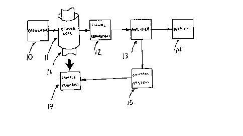
Figure 1 is an algorithm illustrating an overall
block diagram in an on-line closed loop control
implementation according to the invention;
Figure 2 is a schematic diagram of the oscillator
and signal refinement circuitry of Figure l;
Figure 3 is a schematic diagram of the amplifier
circuitry of Figure l;
Figure 4 is a schematic diagram of the display
circuitry of Figure 1;
Figure 5 is a schematic diagram of an alternative
embodiment of the oscillator and signal refinement
circuitry;
Figure 6 is a schematic diagram of a further
embodiment of the oscillator and signal refinement
circuitry; and
Figure 7 is a family of curves relating the amount
of zinc galvanizing coating on particular diameters of
bare steel wire to the digital display of the invention
.~ .~
~,....
~330~29
-- 7 --
in test results according to a specific embodiment of the
invention.
With reference now to the drawings, the elements
included in carrying out the invention are illustrated in
Figure 1. They include an oscillator circuit generally
illustrated at 10, a sensor coil generally illustrated at
11, signal refinement circuitry generally illustrated at
12, an amplifier generally illustrated at 13, display
circuitry generally illustrated at 14 and closed loop
control circuitry generally illustrated at 15.
The closed loop control circuitry 15 is used only in on-
line control implementations where it varies the speed at
which the sample transport generally illustrated at 17
pulls the sample 16 through the production system.
The oscillator 10 is shown in more detail in Fig. 2.
It includes a field effect transistor 21, bias resistors
22, 23, 24, coupling capacitor 25 and tank circuit 26.
The tank circuit 26 includes the sensor coil 11, and a
capacitor 27.
The signal refinement circuitry 12 comprises diode
31, and a lowpass filter comprised of variable resistor
32 and capacitor 33.
The components of amplifier 13 are illustrated in
Fig. 3 and comprise the voltage follower stage 50 and
two sample dependent output stages 60, 70, which are
chosen by switch 51. The voltage follower stage 50
comprises a differential amplifier 52 with unity gain
negative feedback. The output stage 60 comprises a
differential amplifier 61 with gain ratio resistors 62,
63, 64, 65 and a potentiometer 66 described in more
detail hereafter. Similarly, output stage 70 comprises a
differential amplifier 71 with gain ratio resistors 72, ~;~
'
., ,,,.~ ~
. , . . ~ .
$:
~33~829
-
-- 8 --
73, 74, 75 and a potentiometer 76 also to be described in
more detail hereafter.
The display circuitry 14 (Fig. 4.) comprises a
voltage sensitive 3-1/2 digit LED display 80 and a
voltage reference created with a potentiometer 81 as will
be described in more detail hereafter.
OPERATION
In operation, the properties measurable are deduced
from the circuit effects attributable to changes in the
resistance of the sensor coil 11 stemming from the
insertion of a sample illustrated diagrammatically at 16
in Figure 1. Two properties of the sample 16 that
determine its effect on the coil resistance are its
magnetic permeability y and its electrical conductivity
~. Both of these quantities are present in skin depth
equation (3) which includes the other variables "~" (skin
depth) and "w" (frequency) as given below.
2 2 (3)
~ =
0.71.W
Both magnetic permeability y and electrical
conductivity a are also present in coil resistance
relationships. The relationship describing the case of a
homogeneous sample is given as equation (4) below where
"a" is the radius of the sample, "1" is the length of the
coil, and "N" is the number of turns in the coil. The
heterogeneous equations are similar but include
additional terms for the extra permeabilities and
conductivities present in the sample.
_ _ (4)
2.~.a.N.N
R = ; 7 kHz < f < 5 MHz
COIL & SAMPLE CORE 1. ~ . a
D
, . .
~, .
~;~
.
~3~0829
g
In the specific embodiment described, the oscillator
10 drives the tank circuit 26, which includes the ~ensor
coil 11, at or very close to its resonant frequency,
which is a high frequency, with no sample in the sensor
coil 11. High frequency is generally considered to begin
at approximately 1 MHz. This signal is half-wave
rectified by diode 31 and the magnitude of the signal is
adjusted with variable resistor 32. The lowpass filter
of resistor 32 and capacitor 33 filter out the A.C.
portion of the signal to produce an average D.C. value.
This signal is then amplified by amplifier 13 and
directed to display 14. The potentiometers 66, 76, 81
are used to optimize circuit response for a range of
samples, set a zero reference and set a calibration
scale.
When a metallic sample 16 such as a coated wire is
inserted into the sensor coil 11, the resistance
presented by the tank circuit 26 increases and the output
signal voltage decreases. Thus the output signal reduces
as more sample is added to the coil core 16. This result
is indicated by the LED display 80 in display circuitry
14.
The actual property sought can be deduced from
tables or graphs generated from experiments on a set of
standard samples, or from a microprocessor with the same
datum stored and being recalled as desired. Such a graph
would be similar to that shown in figure 7.
Two further embodiments of the oscillator circuitry
10 and the signal refinement circuitry 12 are available
as illustrated in Figures 5 and 6.
The Figure 5 embodiment differs from that described
in Figure 2 in three ways. First, coil 11, biasing
resistors 23, 24, and coupling capacitor 25 have been
, ~' '
^ ~3~829
-- 10 --
changed in value. Second, variable resistor 32 and
capacitor 33 of the lowpass output filter have been
removed. Third, capacitor 90 has heen added to the FET
21 biasing circuitry, capacitor 91 has been added to the
tank circuit 26 and the output stage includes diode 92,
capacitor 93, potentiometer 94 and capacitor 95.
Measurement results using this alternative circuit
have improved. This is so since a longer sensor coil 11
is now used to average anomalies inherent in a galvanized
coating. This change reduceæ longitudinal sensitivity
and produces a more useful measurement for industrial
purposes. By rebiasing the FET 21 and returning the tank
circuit 26, higher signal voltage swings have been
produced, increasing instrument sensitivity. A new
output lowpass filter has been added with a diode 92
placed so as to prevent the grounding of the output
signal at high frequencies.
The Figure 6 embodiment differs from the circuit of
Figure 5 in three principal ways. First, coil 11,
biasing resistors 23, 24, coupling capacitor 25,
potentiometer 94 and output capacitor 95 have been
changed in value. Second, tank circuit capacitor 91 has
been removed. Third, variable resistor 100 and
potentiometer 101 have been added to the FET 21 biasing
circuitry.
This circuit also shows improvement in both
performance and production. In terms of performance, the
circuit has been rebiased and returned to slightly
increase sensitivity. Resistor 94 has been substantially
increased to prevent signal loading. In terms of
production, more variable resistors have been added to
overcome low component tolerances. In this way,
production instruments can be easily calibrated to high
standards of accuracy and precision.
r~
~....
`:
:
,
` ~33~829
In operations to date, extensive testing has been
carried out to develop families of curves relating the
amount of zinc galvanizing coating on a bare steel wire
to a corresponding reading on the LED display 80. Figure
7 is a result. Each curve in Figure 7 represents a bare
steel wire of a particular diameter that is subjected to
differing amounts of galvanizing. The x-axis represents
the zinc coat weight per unit surface area of substrate
and the y-axis represents the unitless reading of LED
display 80.
These curves were developed after plotting data
points with a resonant frequency for the coil and
associated capacitance being approximately 3 MHz and
applying a high frequency of approximately 3 MHz to the
coil. For example, a sample datum was measured as
follows. The instrument was zeroed with no sample
inserted into a two inch long, twenty turn sensor coil.
A galvanized steel wire having a bare diameter of .0630"
was then inserted into the coil. The LED display 80
indicated 107. Subsequent gravimetric testing reported
that the coat weight of the sample was 1.29 oz/sq ft.
Thus this datum was a member of the set of data points
with bare steel wire diameter equal to .0630" and its
particular coordinates were (107, 1.29).
This invention is easily applied to the measurement
of other metallic coatings. Uses envisioned include
measurement of the amount of aluminum or chromium coating
on a steel substrate.
Other uses are available according to the invention
for rapid nondestructive electromagnetic testing
techniques in metals besides measuring the amount of the
galvanic coating of wire. For example, producers of
aluminum or copper products might apply electromagnetic
testing to measure thicknesses and diameters with coils
: :
~.. : .: ' - ~ ' . , :
~ - -,:,: ~ , . ... . . .
~. . -, . . .
` ~330823
- 12 -
instead of having to take samples off-line to use
mechanical micrometer techniques or incorporating the use
of an on-line laser micrometer system. ~s a method for
detecting the grade of an alloy, electromagnetic testing
could be used in place of chemical testing. The method
could also find application in the detection of flaws in
the production of metals.
In maintenance and testing applications, it is
contemplated that a portable version could be taken into
the field to measure the dimensions set out instead of
relying upon a micrometer. It also might find use in
testing for flaws other than in the production of metals.
For example, it is important for the safe operation of
elevators, ski-lifts, and cranes that their cables not
have broken strands. It is contemplated that the
measurement technique according to the invention could be
an alternative to the use of bulky X-ray equipment in
locating broken internal strands in a cable.
It is also contemplated that it may be possible to
~0 utilize the teaching of the invention without actual
insertion of the sample into the coil. For example, a
high frequency at approximately the resonant frequency of
the coil and associated capacitance would be applied to
obtain a datum for impedance measurement. A known sample
of a metallic material could then be brought into
proximity to the coil and the impedance change could be
recorded. Further samples would then cause impedance
changes which, again, could be calibrated to determine
the precise metallic characteristics of the unknown
samples. The proximity would of course be equal for all
samples.
: , ~",
.~ .
.
~:,
:
~339829
- 13 -
While a specific embodiment of the invention has
been described, many modifications to the invention will
readily occur to those skilled in the art and the
description herein should be taken as illustrative of the
invention only and not as limiting its scope as defined
in accordance with the accompanying claims.
,;
~:. , . , -, :
. . . . .. . . .