Language selection

Search

Patent 1331035 Summary

Third-party information liability

Some of the information on this Web page has been provided by external sources. The Government of Canada is not responsible for the accuracy, reliability or currency of the information supplied by external sources. Users wishing to rely upon this information should consult directly with the source of the information. Content provided by external sources is not subject to official languages, privacy and accessibility requirements.

Claims and Abstract availability

Any discrepancies in the text and image of the Claims and Abstract are due to differing posting times. Text of the Claims and Abstract are posted:

  • At the time the application is open to public inspection;
  • At the time of issue of the patent (grant).
(12) Patent: (11) CA 1331035
(21) Application Number: 1331035
(54) English Title: ARCING CONTACT ASSEMBLY FOR A CIRCUIT BREAKER
(54) French Title: DISJONCTEUR A COMMUTATION D'ARC
Status: Expired and beyond the Period of Reversal
Bibliographic Data
(51) International Patent Classification (IPC):
  • H01H 33/12 (2006.01)
  • H01H 01/22 (2006.01)
  • H01H 09/38 (2006.01)
(72) Inventors :
  • LEONE, DAVID A. (United States of America)
  • BUXTON, CLIFFORD A. (United States of America)
(73) Owners :
  • SIEMENS AKTIENGESELLSCHAFT
(71) Applicants :
  • SIEMENS AKTIENGESELLSCHAFT (Germany)
(74) Agent: SMART & BIGGAR LP
(74) Associate agent:
(45) Issued: 1994-07-26
(22) Filed Date: 1989-09-19
Availability of licence: N/A
Dedicated to the Public: N/A
(25) Language of filing: English

Patent Cooperation Treaty (PCT): No

(30) Application Priority Data:
Application No. Country/Territory Date
247,462 (United States of America) 1988-09-21

Abstracts

English Abstract


ABSTRACT
An assembly adapted to commutate arcs from between the main
contacts of a circuit breaker to an arcing contact such that a
single arc at the arcing contact can be extinguished and
dispersed within an arc chute. The assembly is adapted to be
pivotally attached to the ends of the main contact carrying arms
and includes are channeling members joined to form a contact
surface An arcing contact can be fixed to the contact surface
such that the arcs from the main contacts are channelled into one
arc at the arcing contact.


Claims

Note: Claims are shown in the official language in which they were submitted.

WE CLAIM:
1. A circuit breaker comprising:
at least three stationary contacts for carrying current;
at least three movable contacts for carrying current;
at least three pivoting contact arms each defining a first
end, wherein each arm carries one movable contact at the first
end;
at least two arc carrying leads each defining a first end
and a second end, wherein the first ends are joined to form a
contact surface and each of the second ends is positioned
adjacent to a pivoting contact arm and each of the second ends is
separated from an adjacent second end by the first end of a
pivoting contact arm; and
means for pivotally attaching the second ends of the arc
carrying leads at the first ends of the pivoting contact arms.
2. The circuit breaker of claim 1 further comprising an arcing
contact fixed to the contact surface.
3. The circuit breaker of claim 2, wherein the first ends of
the pivoting contact arms and the second ends of the arc carrying
leads each include a pivot pin opening, and the means for
pivotally attaching comprises a pivot pin adapted to pass through
the pivot pin opening.
4. The circuit breaker of claim 3, wherein the first ends of
the arc carrying leads are joined by a rivet.
5. A molded case circuit breaker comprising:
at least four stationary contacts for carrying current;
at least four movable contacts for carrying current;
at least four pivoting contact arms each defining a first
end, wherein each arm carries one movable contact at the first
end;

at least two arc carrying members each defining a first end
and a second end, wherein the first ends are joined to form a
junction and each of the second ends is positioned between two
pivoting contact arms; and
means for pivotally attaching the second ends of the arc
carrying leads at the first ends of the pivoting contact arms.
6. The circuit breaker of claim 5 further comprising an arcing
contact fixed to the junction.
7. The circuit breaker of claim 6, wherein the first ends of
the pivoting contact arms and the second ends of the arc carrying
leads each include a pivot pin opening, and the means for
pivotally attaching comprises a pivot pin adapted to pass through
the pivot pin opening.
8. The circuit breaker of claim 7, wherein the first ends of
the arc carrying members are joined by a rivet.
9. An arcing contact assembly for a circuit breaker of the type
including at least three stationary contacts for carrying
current, at least three movable contacts for carrying current,
and at least three pivoting contact arms each defining a first
end, wherein each arm carries one movable contact at the first
end, the arcing contact assembly comprising:
at least two arc channelling members each defining a first
end and a second end, wherein the first ends are joined to form a
contact surface and each of the second ends is adapted to be
positioned adjacent to a pivoting contact arm and each of the
second ends is adapted to be separated from an adjacent second
end by the first end of a pivoting contact arm, the arc
channeling members functioning to channel arcs from the contacts
to the contact surface;

means for pivotally attaching the second ends of the arc
carrying leads at the first ends of the pivoting contact arms;
and
means for joining the second ends.
10. The arcing contact assembly of claim 9 further comprising an
arcing contact fixed to the contact surface.
11. The arcing contact assembly of claim 10, wherein the first
ends of the pivoting contact arms and the second ends of the arc
carrying leads each include a pivot pin opening; and the means
for pivotally attaching comprises a pivot pin adapted to pass
through the pivot pin opening.
12. The arcing contact assembly of claim 10, wherein the means
for joining the second ends comprises a rivet.

Description

Note: Descriptions are shown in the official language in which they were submitted.


133~03~
20365-2986
BACXGROUND OF INVENTION
This invention relates to a clrcuit breaker, and more
particularly, to a plvoting arcing contact assembly associated
with the main current carrying contacts of the clrcult breaker.
Under certaln conditions, which are frequently present
when the current carrying contacts of a circuit breaker are
opened, an arc ls generated between the contacts. Depending on
the inten~ity and duration of the arc, the contact material, which
in many cases i8 a precious metal, experiences varying degrees of
deterioratlon and/or separation of the contact material from the
contact carrylng arms. For example, the contact surfaces can be
eroded such that the reslstance of the lnterfaces between contacts
lncreases causing contact heating and further deterioration of the -~
contacts.
To reduce the duration of arcing at the current carrying ~-
contacts, it is i~portant to move the arcs fro~ the contacts.
Thiæ can be done by causlng arcs generated at the contacts to
co~outate to a hlgher reslstance le~ expensive naterial. Arc
horn6 or arcing contacts can be used to perforo thls functlon.
For exa~ple, U.S. patent 4,713,504 discloses an arcing contact
,~. ~ , -:
~ hlngedly nounted for reduclng arclng between separatlng contacts.
, d~ ~ .
Subsequent to oovlng arcs from between current carrying
contacts to arcing contacts, it is ioportant to extingulsh the
arc~ and/or nove the arcs lnto an arc chute. Accordingly, it
would be advantageous to effectlvely commutate all of the arcs ;
generated at the current carrylng contactJ ln a way which
consolldates all of the arc~ lnto a single arc whlch can be
extlngulshed and/or ~oved into an arc chute. `~
~ ~ , 4~

- -: 1331~3~ -
SUMMARY OF THE INVENTION
An object of the present invention is to provide an assembly
which is adapted to funnel or channel arcs from the main contacts
of a circuit breaker to a pair of arcing contacts where a single
arc can be extinguished into an arc chute.
Accordingly, there is provided a circuit breaker comprising
at least three stationary contacts for carrying current, at least
three movable contacts for carrying current and at least threè
pivoting contact arms each defining a first end wherein each arm
carries one movable contact at the first end. The improvement to
the circuit breaker comprises at least two arc carrying leads
each defining a first end and a second end. The first ends are
joined to form an arcing contact surface, each of the second ends
is positioned adjacent to a pivoting contact arm and each of the
second ends is separated from an adjacent second end by the first
end of a pivoting contact arm. The circuit breaker further ~--
includes a means for pivotally attaching the second ends of the ~ ;
arc carrying leads at the first ends of the pivoting contact - ~
arms. --
An advantage of the present invention is that it provides ~ -~
means for carrying an arc from each movable contact to the arcing
contact surface by providing an arc carrying lead adjacent to
each pivoting contact arm. Additionally, the present invention
has the advantage of eliminating the need to displace one or more
pivoting contact ar~s with contact arms adapted to carry an
arcing contact, wherein the contact arms are also pivoted at the
pivot joint for the pivoting contact arms. An example of a
contact arm for carrying an arcing contact which is pivoted at
the pivot for the other contact arms is disclosed in U.S. patent
3,365,561. -
Various other objects and advantages of the present
invention will become apparent from the following description,
- with reference to the accompanying drawing.
.

- `` 133103~
BRIEF DESCRIPTION OF THE DRAwINGS -- --
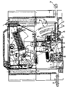
FIG. 1 is a side view of a circuit breaker including a pair of
arcing contacts;
FIG. 2 is a side view of a contact arm including a pivotally
attached arc horn;
FIG. 3 is a top view of the arc horn;
FIG. 4 is a side view of the arc horn; and
FIG. 5 is a top view of the contact arm assembly including the -
pivotally attached arc horn.
DETAILED DESCRIPTION OF THE PREFERRED EMBODIMENT
~ eferring now to FIG. 1, FIG. 1 illustrates a molded case
circuit breaker including movable current carrying contacts 10
carried by a contact carrying arm 14, stationary current carrying . :~ contacts 12, an arcing contact assembly 22 and an arc chute 24.
The pivoting contact carrying arm 14 cooperates with a pivot
joint 16 such that the contacts 10, 12 can be opened and closed
to control the flow of current between the terminals 18, 20 of
the circuit breaker.
The preferred embodiment of the arcing contact assembly 22
is illustrated in more detail in FIGS. 2-5. The contact assembly
22 includes five arc channelling members 26 which each include a
pivot hole 28 and a rivet hole 30. The members 26 are joined . . . ~-~
such that they form an arcing contact surface 32 and five contact ~ ~
~: carrying arm engaging portions 34. The members 26 are joined ~ ::.~--~.
2S with a rivet 29 which passes through the rivet holes 30. The ... -~
~-~ arcing contact surface 32 can be used as a location for attaching
~: an arcing contact 36. -:
The engaging portions 34 are interposed between, and
ad~acent to, the contact carrying arms 14 such that the engaging
portions 34 are separated by at least one contact carrying ar~
14. To al}ow the arcing contact assembly 22 to pivot relative to
the contact carrying arms 14, a pivot pin 38 engages the pivot
holes 28 of the engaging portions 34 and the pivot holes of the
contact carrying arms 14. ~`
4 ;~
, ,.. , ~.:. ..

~`-` 1331~3~i
In general, the arcing contact assembly 22 functions to
channel or funnel substantially all of the arcs which occur : ~-
between the contacts 10, 12 into one arc between the contacts 36,
40. When the contact 10 is put into motion so that the contacts
S 10, 12 are separated, the mass of the arcing contact assembly 22
and spring 44 causes the assembly to pivot relative to the
contact carrying arms 14 such that the contacts 36, 40 remain
closed for a period of time after the contacts 10, 12 are opened. :
As the contacts 36, 40 are separated, one main arc is formed ~_ 9-~-8
10 between the contacts ~, 40. As the contacts 36, 40 are furthercy~q~
separated the main arc is extinguished into the arc chute 24,
which includes a plurality of metal plates 42.
While one embodiment of an arcing assembly has been shown
and described in detail herein, various other changes and : -
15 modifications may be made without departing from the scope of the . -
present invention.
' .
: ' ..
~ .
. -:"'
;~ . , ' '
' :,'
~'
` - '
- . , S
.
. .~

Representative Drawing
A single figure which represents the drawing illustrating the invention.
Administrative Status

2024-08-01:As part of the Next Generation Patents (NGP) transition, the Canadian Patents Database (CPD) now contains a more detailed Event History, which replicates the Event Log of our new back-office solution.

Please note that "Inactive:" events refers to events no longer in use in our new back-office solution.

For a clearer understanding of the status of the application/patent presented on this page, the site Disclaimer , as well as the definitions for Patent , Event History , Maintenance Fee  and Payment History  should be consulted.

Event History

Description Date
Inactive: IPC from MCD 2006-03-11
Time Limit for Reversal Expired 2003-07-28
Letter Sent 2002-07-26
Grant by Issuance 1994-07-26

Abandonment History

There is no abandonment history.

Fee History

Fee Type Anniversary Year Due Date Paid Date
MF (category 1, 3rd anniv.) - standard 1997-07-28 1997-06-17
MF (category 1, 4th anniv.) - standard 1998-07-27 1998-06-17
MF (category 1, 5th anniv.) - standard 1999-07-26 1999-06-08
MF (category 1, 6th anniv.) - standard 2000-07-26 2000-06-14
MF (category 1, 7th anniv.) - standard 2001-07-26 2001-06-12
Owners on Record

Note: Records showing the ownership history in alphabetical order.

Current Owners on Record
SIEMENS AKTIENGESELLSCHAFT
Past Owners on Record
CLIFFORD A. BUXTON
DAVID A. LEONE
Past Owners that do not appear in the "Owners on Record" listing will appear in other documentation within the application.
Documents

To view selected files, please enter reCAPTCHA code :


To view images, click a link in the Document Description column. To download the documents, select one or more checkboxes in the first column and then click the "Download Selected in PDF format (Zip Archive)" or the "Download Selected as Single PDF" button.

List of published and non-published patent-specific documents on the CPD .

If you have any difficulty accessing content, you can call the Client Service Centre at 1-866-997-1936 or send them an e-mail at CIPO Client Service Centre.


Document
Description 
Date
(yyyy-mm-dd) 
Number of pages   Size of Image (KB) 
Abstract 1995-08-28 1 53
Drawings 1995-08-28 3 167
Claims 1995-08-28 3 187
Descriptions 1995-08-28 4 304
Representative drawing 2001-12-03 1 22
Maintenance Fee Notice 2002-08-25 1 177
Fees 1996-06-19 1 75
Prosecution correspondence 1989-10-30 1 28
Examiner Requisition 1992-08-31 1 53
Prosecution correspondence 1992-12-08 2 44
Courtesy - Office Letter 1989-12-10 1 42
PCT Correspondence 1994-05-08 1 20