Note: Descriptions are shown in the official language in which they were submitted.
1~3~ ~44
1 64077-782
Field of the Invention:
The present invention relates to forage harvesters and
more particularly to a method and apparatus for automatically
adjusting the position of a shear bar so that it is parallel to a
rotating cutter head, no operator intervention being required
except for actuating a switch to initiate the adjustment
operation.
Backcround of the Invention:
Lindbloom et al. United States Patent No. 4,436,248
discloses an apparatus for manually adjusting the shear bar in a
forage harvester relative to a rotating cutter head carrying a
plurality of knive~. In the patent adjustment is accomplished by
manually turning a first or a second knob to thereby move a first ~ -
or a second end of a shear bar. In actual practice, adjustment is
carrled out by turning the knobs and listenlng for the "tlck" as
-, :, ~, -
the rotating cutter blades make contact with the shear bar. When
the ~tick~ ls heard, the shear bar is backed off untll the sound
ls no longer heard. The
~1;
' ':
,~ ' ,
':
':` .i ` ~, -,, ,,, ~, .
1331~4
-2-
adjustment i8 imprecise, time consuming, and requires
that the operator leave his seat to accomplish the
adjustment.
German DE 33 45 749A discloses the use of a
single motor for simultaneously driving linkages
connected to both ends of a harvester qhear bar to
automatically adjust the shear bar relative to a
rotating cutter head. Because both linkages are driven -
by a single motor, and are thus driven equally, it is
not possible to automatically adjust the shear bar if
it is not initially parallel to the cutter head and
parallelism must be effected manually before the
automatic adjustment may be accomplished.
In Keeney (W0 82/01299) a potential between a ~
shear bar and a cutter head is monitored and a --
microprocessor controls a singIe motor to adjust the
shear bar. In this device too, it is necessary that
paralleli~m be first established by manual adjustment.
German OS 30 10 416 discloses the use of an -
acoustic or optical non-contact sen~or for monitoring
the gap between the fixed and moving blades of a ~-
harvester. In this device the sensor monitors the gap f
between the fixed and moving blades by sensing the
proximity of the moving blades and if the gap varies - ~
beyond predetermined limits the harvester operation is i~-
stopped. No provision is made for utilizing the sensor
output to adjust the gap.
In an automatic adjustment system wherein --~
contact between the shear bar and rotating cutter head -
is sensed to control the adjustment, it is essential
that the vibration sensor be in good operating
condition. If the sensor or its associated wiring is i `~`
faulty, or the cutter head is not rotating, the
ad~ustment mechanism may drive the shear bar too far ~ ~ -
toward the blades of the rotating cutter head thus
,,: `, , .
,, ~ "".,"",
......
~' '` , ""''..
- 1~31~4
damaging the shear bar, cutter blades and/or adjustment
drive mechanism. In accordance with one aspect of the
present invention, the operability of the vibration
sensor is repeatedly checked before and during a shear
bar adjustment operation and checks are made to insure
that the cutter head is rotating at or above a
predetermined minimum speed.
Background noise, that is, the vibrations
induced by normal harvester operation, is particularly
troublesome when vibration sensors are utilized in an
automatic shear bar adjustment system. In accordance
with a further aspect of the present invention, means
are provided for adapting the threshold of the
vibration detection system in accordance with the level
of background noise 80 that vibrations resulting from
contact between the shear bar and rotating cutter
blades may be reliably distinguished from vibrations
resulting from normal harvester operation.
SUMMARY OF THE INVENTION
An object of the present invention i9 to
provide a method and apparatus for automatically
adjusting a shear bar relative to a rotating cutter
head even though the shear bar and cutter head may not
be parallel to each other prior to initiation of the
adjuatment operation.
An object of the invention is to provide a
method and apparatus for adjusting a shear bar relative
to a rotating cutter head by alternately energizing a
first or a second drive motor to alternately move a
first or a second end of the shear bar relative to the
rotating cutter head.
`` 13310~
--4--
Another object of the invention i9 to provide
an adjusting apparatus including first and second
bidirectional motors each attached to a shear bar near
a respective end thereof, an acoustic sensor mounted on
the shear bar support for sensing vibrations induced
when a rotating cutter head contacts the shear bar, and
an electrical control circuit or microprocessor
initiated by actuation of a switch for automatically
controlling the motors in response to vibrations sensed
by the sensor, to thereby adjust the shear bar relative
to the cutter head. Prior to and during the adjusting
procedure the microprocessor senses the speed of
rotation of the cutter head and initiates movement of
the shear bar only when the cutter head is rotating at
lS or above some predetermined speed. -
A further object of the invention is to
provide an electrical control circuit as described
above wherein the microprocessor not only controls the
motors but also controls the testing of the operability
20 of the sensor and adjusts its sensitivity. A knocker ;`,
or impact element i9 mounted on the shear bar support ` `
to induce vibrations therein in response to pulses ~ ~ -
generated under the control of the microprocessor. The
vibrations are sensed by the sensor and the resulting
electrical signal applied to an analog to digital
converter to develop a digital indication of the sensor ' -
output. The microprocessor then compares the digital - - ;
indication with a reference value and halts the ,- : -
adjuQting procedure if the digital indication does not t -
exceed the reference value.
Another object of the invention is to provide
an electrical control circuit as described above and - ~ ~-
further including means for adjusting the sensitivity
of the control circuit: to output signals from the knock
35 sensor. The sensitivity is adjusted by sensing the ~ ~
.. . ;:
~ 133~4
64077-782
"noise" vibrations in the shear bar support and developing digital
indication of the noise. During the adjustlng procedure this
digital indication is added to a safety factor value and the
output of the knock sensor (after analog to digital conversion) ls
compared to the sum. Thus, the magnitude of the output signal
from the knock sensor requlred to indicate impact between the
shear bar and cutter head varies depending on the noise vibrations
induced in the shear bar by normal harvester operation.
In accordance with the present invention, there is
provided in a cuttlng apparatus havlng an adjustably flxed shear
bar cooperating with a rotating cutter head to cut material
passing between the bar and head, the improvement comprislng:
flrst and second bidirectional motors; flrst means responslve to
said flrst motor for moving a first end of said shear bar relative `~
to sald cutter head; second means responsive to said second motor
for movlng a second end of said shear bar relative to said cutter
head; sensing means for sensing contact between said shear bar and
sald cutter head; start control means; and, electrical control ;~
means responsive to said start control means and said sensing
means for controlling said flrst and second motors to adjust the
position of said shear bar; sald electrical control means
includlng means for alternately energlzlng one of said motors and
then the other whereby one end and then the other end of said
shear bar is moved until said shear bar is adjusted relative to
said cutter head.
In accordance with another aspect of the invention,
there ls provided in a cutting apparatus havlng an adjustably
flxed shear bar cooperatlng with a rotating cutter head to cut ~-
3~la~
5a 64077-782
materlal passlng between the bar and head, and flrst and second
bldlrectlonal motors connected to move flrst and second ends of
sald shear bar, a method of ad~ustlng the posltlon of sald shear
bar relatlve to sald rotatlng head, comprlslng the steps of,
energlzlng sald flrst motor to move a flrst end of sald shear bar
toward sald head for a flxed lnterval of tlme or untll lt contacts .
sald cutter head and then energlzlng sald flrst motor to move sald ~:
flrst end away from sald cutter head a predetermlned dlstance, -
deenerglzlng sald flrst motor; energlzlng sald second motor to
move a second end of sald shear bar toward sald cutter head for a .. . :
flxed lnterval of tlme or untll lt contacts sald cutter head and
then energlzlng sald second motor to move sald second end away
from sald cutter head sald predetermlned dlstance; deenerglzlng .: .
sald second motor~ and, repeatlng each of the precedlng steps . -
untll sald flrst and second ends of sald ~hear bar each contacts
sald cutter head on each of two separate energlzatlons of the
respectlve motors whlch move sald ends.
In accordance wlth another aspect of the lnventlon,
there ls provlded ln a cuttlng apparatus havlng an ad~ustably : ~;
flxed shear bar cooperatlng wlth a rotatlng cutter head to cut
materlal passlng between the bar and head, the lmprovement :~
comprlslng, vlbratlon senslng means for senslng vlbratlons ln
sald shear bar~ analog to dlgltal converter means responslve to
sald senslng means for produclng a dlgltal value lndlcatlve of the ~ -
magnltude of vlbratlons ln sald shear bar~ motor means for
selectlvely movlng sald shear bar toward or away from sald cutter -`
head~ and, sequence control means for selectlvely energlzlng sald
motor means to move sald shear bar away from sald cutter head, :~
~:,
~, ; ,
., __ . :
` - 133104~
.
5b 64077-782
senslng sald dlgltal value and addlng a reference value thereto to
obtaln a sensltlvlty level value, movlng sald shear bar toward
sald cutter head while sampllng sald dlgltal value for evldence of
contact between sald shear bar and cutter head, and stopplng
movement of sald shear bar toward sald cutter head when ~ald
sampled dlgltal value exceeds sald sensltlvlty level value.
In accordance wlth another aspect of the lnventlon,
there ls provlded ln a materlal processlng machlne havlng a palr
of members for processlng materlal lntroduced therebetween, a
mechanlsm for movlng one of the members towards and away from the
other member and a control system cooperatlng wlth the mechanlsm
to automatlcally ad~ust clearance between the members, :-~
characterlzed by: the control system lncludlng means for
automatlcally movlng the one member towards the other member; and
means for automatlcally stopplng movement of the one member lf the .
one member movlng mechanlsm operates for at least a certaln tlme
perlod wlthout engagement between the members.
In accordance wlth another aspect o~ the lnventlon,
there ls provlded ln a cuttlng apparatus havlng an ad~ustably
flxed shear bar cooperatlng wlth a rotatlng cutter head to cut
materlal passlng between the bar and head, the lmprovement
comprlslng. flrst and second bldlrectlonal motors1 flrst means
responslve to sald flrst motor for movlng a flrst end of sald
shear bar relatlve to sald cutter head~ second means responslve to
sald second motor for movlng a second end of sald shear bar :~
relatlve to sald cutter head1 senslng means for senslng contact
between sald shear bar and sald cutter head~ start control means, `
and, electrlcal control means responslve to sald start control ~ p~
1331~4
5c 64077-782 -
means and sald senslng means for controlllng sald flrst and second J `
motors to ad~ust the posltlon of sald shear bar~ sald electrlcal ~ ~ :
control means lncludlng means for alternately energlzlng one of : ;:
sald motors and then the other whereby one end and then the other .
end of sald shear bar ls moved untll sald shear bar ls ad~usted :.
relatlve to sald cutter head, whereln sald electrlcal control
means comprlses a mlcroprocessor, a memory, an analog to dlgltal ; ;~
converter, an lnterface adapter lnterconnected by bus means, sald
senslng means belng connected to sald analog to dlgltal converter, . :-
and means connected to sald lnterface adapter for energlzlng and
controlllng the dlrectlon of rotatlon of sald motors ln accordance
wlth slgnals applled by sald senslng means to sald analog to -
dlgltal converter and a program executed by sald mlcroprocessor,
whereln sald electrlcal control means lncludes means for senslng ~ .
the rate of rotatlon of sald cutter head and deenerglzlng sald .-.
motors lf sald rate of rotatlon ls less than a predetermlned ~
mlnlmum rate. -: :
. . " , .
Other ob~ects of the lnventlon and lts mode of operatlon ~ -
wlll become apparent upon conslderatlon of the followlng
descrlptlon and the accompanylng drawlngs.
BRIFF DFSCRIPTION OF THF DRAWINGS - --~
Flgure l schematlcally lllustrates an ad~ustment control ~ .
system for automatlcally controlllng the ad~ustment of a shear bar :~
relatlve to a rotatlng cutter head~
Flgure 2 ls a dlagram useful ln explalnlng the method of
ad~ustlng the shear bar1
Flgure 3 lllustrates the mountlng of an lmpact element
and a vlbratlon sensor on a shear bar support~
. '
1 3 3 1 ~ 4 4
5d 64077-782
- Flgures 4~ and 4B, when arranged as shown ln Flgure 4C,
comprlse a clrcult dlagram of the electrlcal controls for
controlllng the shear bar ad~ustment and the testlng and
sensltlvlty ad~ustment of the vlbratlon sensor;
Flgure 5 shows the knock sensor output clrcults and the
clrcults for applylng reference slgnals to the analog to dlgltal
converter;
Flgure 6 shows the INITIALIZF routlne~
~ lgure 7 show~ the RFADY routlne
,`'';`'~'''-..'' ;.''"
B
~ .
- 1 3 3 1 ~ 4 4
6 64077-782 ~
Flg. 8 shows the NMIR routine; -
Flg. 9 shows the TSTGEN routlne;
Flgs 10A and 10B show the GETNOI routlne;
Flg. 11 shows the PULOUT routlne;
Flgs. 12A-12C show the ADJUST routlne; and,
Flg. 13 shows the PULFOUT subroutlne.
DETAILED DESCRIPTION OF THE INVENTION
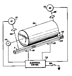
Flg. 1 schematlcally lllustrates a cuttlng apparatus
comprlslng a rotatlng cutter head 100 and an ad~ustable but flxed
10 shear bar 102. The shear bar 102 ls mounted on a support bar 104
but is movable wlth respect to the support bar by actuatlon of
llnkages such as a palr of lead screws 106, 108. The cutter head - -¦ carrles a plurallty of knlves whlch, as the cutter head rotates,
cooperate wlth the shear bar 102 to cut materlal passlng between
the cutter head and the shear bar.
A flrst bldlrectlonal motor 110 drlves lead screw 106
whlch ls llnked to a flrst end A of the shear bar. A second bl-
dlrectlonal motor 112 drlves lead screw 108 whlch ls llnked to a --
second end B of the shear bar.
Ad~ustment of the shear bar 102 relatlve to the cutter
head 100 ls accompllshed wlth the cutter head rotatlng. A tacho-
meter 114 senses rotatlon of the cutter head shaft and produces a
sequence of pulses lndlcatlng the cutter head speed whlch ls
applled to an electrlcal control clrcult 116. Ad~ustment ls
accompllshed by senslng vlbratlons, or the absence of vlbratlons
ln the support bar 104 resultlng from contact, or the lack of con-
tact, between the shear bar
.
.
, X
` - 13310~4
102 and the knives of the rotating cutter head. A
vibration sensor 118, which may be a crystal, i8
attached to the support bar 104. The support bar has
an internally threaded hole 120 (Fig. 3) for receiving
a threaded mounting stud provided on the crystal mount.
Since ad justment is accomplished by sensing
vibrations resulting from contact between the shear bar
and the knives of the cutter head, it i8 essential that
shear bar adjustment not be attempted if the sensor 118
is not functioning. A solenoid-actuated knocker 122 is
provided for determining the operability of the knock
sensor. The knocker ha~ a threaded mounting stud which
secures the knocker to an internally threaded hole 124
in the support bar 104. The solenoid has a spring-
bl~--d armat~lre which carri-- an impact lement 126 at
its end. When the solenoid is energized it drive~ the - ~ -
impact element 126 into contact with the support bar
104, inducing vibrations in the support bar which are
sensea by the sensor 118. The electrical controls 116
pulse the knocker 122 and analyze the signals returned
by the ~ensor 118. -
A pussh-button switch 128 is provided on a
control panel near the operator. Each time the
operator actuates switch 128, the electrical control
circuit 116 checks the operability of sensor 118 as
well as its sensitivity, check~ to determine that the - : --
, ~. - , ~ .,
cutter head is rotating and selectively energizes first
one of the motors 110, 112 and then the other until the
cutter bar 102 i8 essentially parallel to the cutter
head 100 and spaced therefrom by no more than a small
predetermined distance on the order of a few
thousandths of an inch.
The electrical control circuits 116 are -
illustrated in Figs. 4A and 4B and include a
microproce~sor 200, an EPROM 202, an analog to digital
~r
1331044 1 :
--8--
converter (ADC) 204, a peripheral interface adapter
(PIA) 206, a versatile interface adapter (VIA) 208, an
address decoder or selector 210 and a watch dog circuit
212. All units except the watch dog circuit are
S interconnected by an 8-bit bidirectional data bus 214
and/or a 16-bit addres~ bus 216.
Since the details of the VIA 208,
microprocessor 200, EPROM 202, ADC 204, PIA 206, and
address decoder 210 are well known in the art, they are
not de~cribed in detail herein but a brief description
of each is given below.
The microprocessor 200 may be a~Motorola type
6802 microprocessor including an internal memory for
limited storage of data during a processing
operation. The microprocessor has eight input/output
terminals D7-D0 which are connected to the data bus 214
and sixteen output terminals A15-A0 for supplying an
address generated within the microprocessor to the
address bus 216. When a data register within the
microprocessor is loaded with a byte of data for
application to the data bus the microprocessor drives
the signal R/W on lead 218 to logic p and when the data -~:
rogister i- to receive a byte of data from the data bus
the microprocessor causes the signal R/W to go to logic -~
1. When the microprocessor places an address on the
address bus it generates the signal Valid Memory
Addro-- (VMA) on lead 220 and this signal is applied to
tho gating input of address decoder 210. The ~ -
microprocessor outputs a single phase clock onto lead
222 from its E terminal.
Microprocessor 200 has a non-masXable
interrupt (NMI) input terminal. A low-going signal at
this terminal causes the microprocessor to initiate a
non-maskable interrupt sequence. The microprocessor
also has a reset input terminal R and when the signal
. . .
.~.'.,',:
-: 13310~
_9_ ~ ;
on lead 230 goes to low the registers within the
microprocessor are cleared and the microprocessor
becomes inactive. When the signal at terminal R goes
high it cause~ the microprocessor to begin a restart
sequence. ~ -~
Address bus bits A15-A13 are connected to
input terminals of the address decoder 210. Each time
the microprocessor outputs a signal on lead 220, it
enables the adaress decoder to decode the three addres~ -
bits and produce a signal on one of the leads 223~
226. The lead 223 iB connected to the CS2 input of VIA
208. Lead 224 is connected to the OE and CE input~ of
EPROM 202. Lead 225 is connected to the CS input of ;
ADC 204 while lead 226 is connected to the CS2 input
of PIA 206.
The EPROM 202 may be a type 2764 capable of
~toring 8K 8-bit bytes. When the signal on lead 224 is
low the location in the RPROM specified by the address
applied to the EPROM fro~ bus 216 is accessed. The ~ v ~,
location is either written to fro~ the microprocessor,
or read out to the ~icroprocessor, depending upon
whether the signal R/W is low or high, respectively. ;~
EPROM 202 ~tores data and the program which is executed
by the aicroprocessor.
The VIA 208 aay be a type 6522 such as that ; ' ~ ~;
aanufactured by Rockwell or Synertek. AB di-closed at ~ '`d;
page 2526-2530 of the publication IC Master 1980, .
publi~hed by United Technical Publications, the VIA 208
includes 16 addressable registers and interval timers 30 or counters. These registers and interval ti~ers are
addressed by applying an address froa the four low
order of bits of the addres~ bus 216 to the register
select input RS3-RS0. Data is read from, or entered ! ~',:`~ ``~ ~'.'`'', '
into the registers and count-r~ through data terainals ` ~
D7-D~ which are connocted to the data bus 214. The VIA ~ r~-
; ~;:``
: : ~
.~ ~
133~
--10--
i8 enabled only when the microproce~sor outputs a
hexadecimal address, the high order bits of which cause
the addresg decoder 210 to produce a low signal on lead
223 which enables the chip select (CS2) input of the
VIA. The register or counter which is accessed is
determined b~ the four low order bits of the address
bus which are applied to register select inputs RS3-RS0
of the VIA. The accessed register or counter is either
read from or written into depending upon whether the
microprocessor 200 outputs a high or low level signal,
respectively, on lead 218 to R/W terminal of the VIA.
The p2 input of the VIA is a clocking input and is used
to trigger data transfers. It is connected by lead 222
to the E terminal of the microprocessor. All circuits
within VIA 208 are reset when the signal RES on lead
230 goes low. The VIA 208 produces an output signal
CB2 which i8 u8ed for control purposes. The
microprocessor program periodically sends a byte of
control information to VIA 208 to toggle CB2 and pulse
watch dog circuit 212. The watch dog circuit may be
two monostable multivibrator~ connected in series.
Periodic pulses produced on lead 232 by the VIA `: -
periodically reset the watch dog circuit 80 that its
output remains inactive. If the program should fail to - `
send signals to the VIA 208 so that lead 232 i8 pul8ed, ~ ::
the watch dog circuit times out and emit~ an output
signal to reset the microprocessor, the VIA and the PIA
206. The watch dog circuit 212 also has an input 234
which is derived from a monitoring circuit (not shown)
! 30 which monitors the logic circuit supply voltage. If
this voltage should vary out~ide predetermined limits
the signal on lead 234 cause the watch dog circuit 212
to produce an output signal to reset the
microproces~or, the PIA and the VIA. The 5V supply
voltage for the circuits of Pigs. 4A and 4B may be
l33la~ .
derived from the 12V battery which supplies power for
the harvester if it is self-propelled, or from the
battery for the tractor which pulls the harvester.
VIA 208 has two 8-bit input/output ports PA
and PB. The bit position~ of the ports are
individually programmable as either an input or an
output. Two buses, collectively designated 231, - ~-
connect PA and PB to external circuits shown in Fig.
4B. The port A bus is connected to receive the outputs
of a plurality of amplifers 241-244. Amplifier 241 has
one input connected to the 5V logic supply voltage and
a second input connected through two resistor~ 248 and
250 to the 1 2V power ~upply. The ~unctlon betwoen
regigtor9 248 and 250 ig connected through a switch 252
to ground. As long a~ switch 252 is closed the
amplifier applies a logic 0 signal to the bus but when
gwitch 252 is open the amplifier applies a logic 1
signal to the bus. The switch 252 is ag80ciated with
an engage lever (not shown) which is actuated so that a
chain drive causes the cutter head 100 to rotate.
Switch 252 is thus closed when drive power is applied -~
to the cutter head.
Amplifiers 242-244 are arranged in the same
manner as amplifier 241, with switches 254 and 256 - ~ `
being associated with amplifiers 242 and 243,
respectively and switches 258 and 260 being associated
with amplifier 244. Thege switches are all limit
switches for sensing when the ends of the shear bar 102
have reached their limits of travel toward or away from -,
the cutter head 100. Switches 254 and 256 are actuated
when ends A and B, respectively, of the shear bar are
at their limit of travel away from the cutter head.
Switches 258 and 260 are connected in series 80 that
amplifier 244 produces a logic 1 output when either ~-
switch is opened, i.e. when either end A or end B is at ~;
, .
, .
".. ':
-` 1331044
-12-
its limit of travel toward the cutter head. The limit
switches are incorporated within the housings of motors
110 and 112 and are actuated by mechanical
bidirectional counter mechanisms which count rotations
of lead screws 106 and 108.
The tachometer 114 (Fig. 1) produces a
sequence of output pulses at a rate proportional to the
speed of rotation of the cutter head 100. The pulses
are applied over a lead 262 (Fig. 4B) to one input of a
comparator amplifier 264. A voltage divider comprising
two resistor~ 266 and 268 i9 connected between SV and
ground, and a reference voltage i~ applied from the
junction of the resistors to a second input of
amplifier 264. When the tachometer produces an output
lS pulse exceeding the magnitude of the reference voltage,
amplifier 264 applies a logic 1 signal to bit position
6 of the B bus. These pulses are counted by a counter
(timer 2) in VIA 208. ~ -
Five bits of port B of the VIA are connected
by a B bus to five inverters 270-274. The outputs of
inverters 270-273 are connected to the bases of
grounded emitter transistors 280-284, respectively.
The collectors of tran~istors 280-283 are connected to
the 12V source through the coils of relays K2-K5,
resepctively, while the collector of transistor 285 i9 ...
connected to the 12V source through an audible alarm
286.
The direction of rotation of motor 110 i8
controlled by the contacts of relays K2 and K3, only
one of which may be energized at any given time. If
relay K2 is energized the motor rotates in one
direction to move end A (Fig. 2) of the shear bar 102
inwardly toward the cutter head 100. The current flow
path extend~ from 12V through contacts K2a, motor 110,
normally closed contacts K3b and resistor 288 to
~ 13310~4 .
-13-
ground. On the other hand, if relay K3 is energized, a
circuit extends from the 12V source through contacts
K3a, motor 110, contacts K2b and resistor 288 to
ground. Since current flow is in the opposite
direction through the motor, it rotates in the opposite
direction to move end A of the shear bar away from the
cutter head. If neither relay K2 or K3 i~ energized,
motor 110 does not rotate because contacts K2a and K3a
are both open.
Relays K4 and KS have normally open contacts
K4a and K5a and normally closed contacts K4b and K5b.
Relays K4 and K5 control the motor 112 in exactly the
~ame manner that motor 110 i9 controlled by relay~ K2
and K3.
Bit 7 of port B of VIA 208 is controlled by
one of the timers in VIA 208. The timer (TlC) causes
an interrupt pulse to appear at PB7 each time the ~ ~
counter is loaded, the delay between the loading of the - -
counter and the occurrence of the pulses being
determined by the value entered into the counter. PB7 ~ ~
is connected by a lead 235 to the NMI input of - ~ --
microporcessor 200 ~o that the program being executed ~ -
by the microprocessor i~ interrupted periodically and a
routine is executed to read the various switches and `~
output various control signals to the VIA and PIA
busses.
One bit of the PB buis is connected to a type
3548 PNP driver circuit. The output of the driver -
circuit is connected to ground through the solenoid of ; `-
knocker 122. As subsequently explained, the solenoid
is energized to induce vibrations in the shear bar 104
and the resulting vibrations sensed by sensor 118 are ~ ~ ;
analyzed to determine its operability. ~ -
The PIA 206 may be a type 6821 peripheral ~ -~
interface adapter. This device is well known in the ~ - -
,"~'"""'"'
. ,
.. . . ..
~: ''':' '''' ''' .
~ 1331Q~
-14-
art and is generally similar to VIA 208 except that it
does not include timers. PIA 206 has two 8-bit ports
PA and PB connected to an A bus and a B bus,
collectively illustrated as buses 300. The bit
positions of the ports are individually programmable
for input or output. Only 2-bit positions of port A
are utilized and they are programmed as input~. These
bit positions receive the outputs of the two amplifiers
302 and 304. A quit switch 306 is connected between ~-
ground and one input of amplifier 302 so that when the
switch is closed the amplifier applie~ a logic 1 signal
to the PIA over the bus. Switch 306 i9 actuated to
halt or interrupt a shear bar ad~usting operation.
The switch 128 i8 connected to one input of
amplifier 304 and when this switch is actuated the
amplifier applies a logic 1 signal to the PIA over the
bus. Switch 128 is the ADJUST switch which initiates a
shear bar adjusting sequence.
Only seven bits~of port B of PIA 206 are ~ -
utilized and they are all programmed as outputs. Each
bit is connected through a driver 310 and an LED 314 to
12V. The LEDs provide an operator with visual alarms
or indications of the status of the ~ystem by
indicating that the system is ready to begin an
adjusting cycle; switch 306 ha~ been actuated to
interrupt an adjusting cycle; a motor 110 or 112 has
stalled; the cutter head is not rotating; an end of
travel has been reached; the sensor 118 is bad; or a - --~
shear bar adjusting operation is in progress.
, 30 ADC 204 may be a type 0844 converter such as
that described at page 3537 of the publication IC
Master, Vol. 2, 1984. The converter has four
multiplexed input channels but only CHl, CH2 and CH4
are utilized in the present invention. The converter
i9 enabled only when the address applied to selector
'
~33la44
-15-
210 by microprocegsor 200 causes the signal on lead 225
to be low. This lead i8 connected to the CS terminal
of the converter.
The microprocessor 200 starts a converter
cycle by placing a command on data bus 214 to select
the channel, and driving lead 218 low. Lead 218 is
connected to one input of two NANDs 320 and 322. The
second input of NAND 320 is connected to +5V and the
output of the NAND is connected to a further NAND
324. The E output of microprocessor 200 is connected
to one input of NANDs 322 and 324 and the outputs of
these NANDs aro connected to the ~ and WR inputs, -
respectively, of the converter. When the signal on
lead 218 is ]ow, ~AND 324 produces a low output when
the clocking signal on lead 222 goes high. The output
., -: . .
of NAND 324 enables the converter 90 that the operation
specified by the command is carried out.
It take~ the converter about 40 microseconds
to convert an analog value to a digital value. The ~ ;-
programming of microprocessor 200 i9 such that once it
initiates a cycle of converter 204 it either wait~ or
performs other operations until at least 40
microseconds have elapsed. The microprocessor then
places an address on bus 216 oo that selector 210 ; ;~
produces a signal on lead 225 to select the
converter. At the same time, the microprocessor drives
the signal on lead 218 high. When the clock signal on
lead 222 goes high NAND 322 produces an output signal
which enables the converter to place the converted j - ~
value on bus 214 from whence it passes to the -;;
microprocessor 200.
.. . . ..
:''
. . .
. ~''~ '
1331~44
-16-
The analog signal from knock sensor 118 is
applied to the CHl input of the A/D converter through a
circuit (Fig. 5) including registors 328 and 329,
amplifiers 330 and 332, a peak hold circuit 334 and a
buffer amplifier 336. A pair of resistors 331, 333
provide a first reference voltage which i8 added to the
knock sengor output signal, the output of amplifier 330
being proportional to the sum of the reference signal
and the differential signal derived from the sensor. A
second reference voltage is derived from a voltage
devider comprising resistors 337 and 339. The second
reference voltage is applied to an amplifier 340 and
the output of the amplifier is tied to a junction 338
between the peak hold circuit 334 and buffer amplifier
336.
The output of amplifier 341 is also applied
to the CH4 input of ADC 204. The ADC 204 is controlled
to operate in a differential mode 90 that it determines
the difference in the magnitude of the analog signals
at CHl and CH4 and converts this difference to a
digital value for tansmission to the microprocessor
200
Resistors 343 and 345 form a voltage divider
which is tapped to provide an input to an amplifier
346. The output of this amplifier is applied to the Vr
input of ADC 204 to set the range of the converter.
During a shear bar ad~usting operation motors
110 and 112 (Fig. 4B) control the movement of the shear
bar. As previously explained, the circuit for
30 energizing either motor in either direction extends
through current sensing re~istor 288. Thus, by
sampling the voltage across the resistor it is possible
to determine if either motor is stalled or if the motor
which should be running is not actually energized. The
35 voltage developed across resistor 288 is applied
. ~
` ` - :''' ' '' - ' ` .~: ' ': . ' . .. ': ' . .
- 1331~
-17-
through an operational amplifier 340, filter circult
342, and buffer amplifier 344 to the C~2 input of ADC
204 where it may be sampled. The ADC does not subtract
the magnitude of the CH4 signal from the CH2 before
doing an ADC.
INITIALIZE, READY and NMIR Routines
When power i9 turned on the microprocessor
200 automatically goes through an initialization ~ ~
routine (Fig. 6) during which the various registers and ~- -
timers in the VIA and PIA are set up. This routine ~ ~
also clears the switch registers or locations in memory -- - ;
202 which store indications of the last sampled state ~ -
of the various switches. The routine then clears the -~
QUIT, PULSW, and RPMOK flags and ~et~ a FIRST flag. In
addition, flags are set to turn off the alarm and alarm -
lights as well as the sensor light. The stack in the
microprocessor 200 is initialized after which the
program proceeds to the first step of the READY
routine.
The READY routine is illustrated in Fig. 7. - ~ ;
It begins at step 700 by setting the flag POUTF. The ~ ~ -
ready light flag is set 80 that the ready light may be
turned on when the NMIR routine is next executed. The
sensor light flag i9 cleared so that the sensor light - -- ;;~
will be turned off the next time VIA 208 pulse~ the
watchdog circuit 212. The BUSY and ALFLG flags are
cleared after which the program proceeds to step 702
where it executes a wait for interrupt instruction. At - -~- ~
about 2.5MS intervals a pulse occurs at PB7 of the VIA ~ ~ -
208 thereby pulsing the NMI input to microprocessor
200. The microprocessor interrupts the routine it i9
executing, in this case the READY routine, and executes
the NMIR routine illustrated in Fig. 8.
`' ~',
--
^` 1331~4
-18-
At step 800, the NMIR routine loads the
counter TIC in VIA 208. This counter is decremented
and when it reaches zero it will again pulse PB7 of the
VIA to initiate another NMIR routine. The VIA next
senses the QUIT and ADJUST switche~ and sets flags
indicating which switches are actuated. In addition,
if both switche~ are actuated a flag PULSW is set. The
microprocessor then addresses the ADC 204 to initiate a
read-convert cycle with CH2 as the selected input.
This samples the motor current and converts it to a
digital value.
At step 801 the CLFLG flag is tested to see
if the clutch in the cutter head drive chain has been
engaged to actuate clutch switch 252. If it has not, a
flag i8 set to turn on one of the indicator lights 314
to indicate that the RPM of the cutter head is not
within limits, and the program branches to step 812 to
turn on the indicator. A return is then made to the
routine which was interrupted. - -
If CLFLG indicates that the clutch is
engaged, the program proceeds to step 802 where the
FIRST flag is tested. This flag was set during the
INIT routine 80 the program proceeds from step 802 to
step 804 where FIRST is cleared and a value is set into
RPMFLG. This value will be counted down to time the
interval during which tachometer pulses produced by the
cutter heaa tachometer 114 will be counted by timer 2
in VIA 208.
At step 806 RPMFLG i8 tested to see if the
! 30 timing interval has elapsed. Assuming it has not, the
program decrements RPMFLG at step 808 and at step 810 ~-
the converted value of the current flowing through the
shear bar ad~usting motors i8 read from ADC 204 and
saved. At step 812 the program sends data to PIA 206
to turn on the appropriate indicator lights. The
, .. .
-lg- 1331~4
program then returns to the routine which as
interrupted to execute the instruction following the
last instruction executed before the interrupt.
In Fig. 7, steps 702 and 704 Comprise a loop
which is repeatedly executed until the test at step 704
indicates that a preset interval of time has elapsed.
The program then tests the ADJSW flag at 706 and the
PULSW flag at step 708. Assuming that the ADJUST
switch i9 not actuated either alone or concurrently
with the QUIT switch, the program executes another Wait
For Interrupt at step 710 and then loops back to step
700. Thus, assuming the ADJUST switch is not actuated
the READY routine is repeatedly executed, the routine
being interrupted every 2.5MS to execute the NMIR
routine. ~ecause FIRST is cleared at step 804 during
the first execution of the NMIR routine after the
cutter head clutch i9 engaged, the program branches
:: :
from step 802 to 806 on the second and subsequent
exectutions of the routine. RMPFLG i9 decremented at -:~ -
step 808 each time the NMIR routine is executed and
after 255ms RPMFLG is reduced to zero. The test at
step 806 proves true and the program moves to step 814 - --
where the count of tachometer pulses accumulated by
timer 2 in VIA 208 is read and saved, and RPMFLG is ~ -
reloaded to time another 255ms interval. --~
RPMMIN is a value representing the minimum
permissible rate of rotation of the cutter head. At - --
step 816 RPMMIN is compared with count of tachometer
pulses. If the count is equal to or greater than :~
RPMMIN the RPMOK flag is set at step 818. If the count ~ -~
is less than RPMMIN then RPMOK is cleared at step
820. After step 818 or 820 the ADC 204 is addressed to
again get the converted value of the adjusting motor -
current. - -
:
13310~4
-20-
TSTGEN Subroutine
~, ~
The purpose of the TSTGEN subroutine to check
the operability of the knock sensor 118 and its
associated circuitry. The TSTGEN subroutine i9
illustrated in Fig. 9 and begins at step 900 where TSTS
is set to 3, SAMPLE is set to 64, and OKTST is
cleared. At step 901 a value is sent to VIA 208 which
causes the VIA to output a signal over its B bus to
energize driver 275 thereby energizing the knocker
solenoid 122. In Fig. 3, the clapper 126 i8 driven
against support bar 104. This induces vibrations in
the support bzlr which may be sensed by knock ~ensor 118
to produce an analog signal. This signal passes
through the circuit of Fig. 5 and is applied to the CHl
~nput of ADC 204.
At step 902 the microprocessor addresses the
ADC and starts a conversion cycle. At step 903 the
microprocessor executes a delay loop waiting for 40 -
microseconds while the ADC samples the CHl and CH4
inputs and converts the difference into a digital ~"
value. At step 904 the microprocessor addresses the
ADC and save~ the digital value which i8 an indication
of the output of the Xnock sensor.
The program then enters a loop comprising
steps 905-910. At step 905 another analog to digital
conversion cycle is started, at step 906 the
microprocessor waits for completion of the conversion
cycle, and at step 907 the converted vlaue is retrieved
from the ADC. Step 908 compares the late~t (next)
sample value with the previously converted value saved
and the larger of the two values is saved. The value
of SAMPLES is decremented and tested at step 910 and if
it is not decremented to zero the program loops back to
step 905. Thus, for one test the knocker solenoid is
1331~
--21--
pulsed once at step 901 to induce vibration into the
shear bar support and the output of the knock sensor i8
sampled 64 times, the largest of the 64 samples being
saved at step 909. After the 64th sample the test at
step 910 proves true and the program proceeds to step
911 where the saved largest sample is compared with a
value representing the minimum acceptable magnitude for
the signal output of the knock sensor.
If the largest sample is greater than or
equal to the minimum acceptable magnitude OKTST is
incremented at step 912 before TSTS is decremented at
step 913. If the largest sample is less than the -,,
minimum acceptable magnitude the program branches from
step 911 to step 913 without incrementing OKTST. - -
At step 914 TSTS is sampled to see if it has - -~
been decremented to zero. If it ha~ not, the program
branches back to step 901 to again pulse the knocker
and determine the largest of the next 64 samples taken '~-
of the output of the knock sensor. ~ -
After three tests have been completed the ~ ~
test at step 914 proves true and at step 915 OKTST is ' ~ ~ -
sampled to see if it is still zero. If it is not, it
means that the knock sensor test was successful and !.
found at least one sample larger than the required !. '' ' ~. ;~
25 minimum value. If OKTST is still zero it means that
the knock sensor is not sensitive enough to be used, or
its output circuitry is not functioning properly. The
program branches to step 916 to set flags to turn on an
indicator 314 and the alarm 286. A jump is then made -
30 to an aIarm routine to sound the alarm and turn off the
motors. Although the ALARM routine is not illustrated,
it may be noted that the program continuously executes
a loop in the AI~RM routine until the operator turns
the power off and then on so that the program again
35 executQs the I~ITIAL.IZE routine illustrated in Fig. 6.
. . '
: '; : '
133 1 ~ 4 4 !
-22-
The Get Noise Subroutine
The subroutine GETNOI iB illustrated in Figs.
10A and 10B. During execution of this routine the
output of the knock sensor is tested up to four times,
each test comprising 4096 samples. The maximum number
of tests is ~et at step 1000 and the number of samples
is set at step 1009. The purpose of GETNOI is to
determine the noise vibrations induced in the shear bar
as a result of normal machine operation, or more ~ --
specifically the output of the knock sensor in response
to these vibrations. The subroutine develop~ a digital
indication of the noise and thi~ digital indlcatlon i3
subsequently used in the ADJUST routine described below
to set the sensitivity of the system to the output
signal from the knock sensor.
At step 1001 the RPMOK flag is tested. This
flag is set at step 818 of the NMIR routine if the
cutter head speed is equal to or greater than the
minimum speed represented by RPMMIN. If the cutter -~
head is not up to speed the program branches to step
1002 where a flag is set to turn on the alarm. At step
1003 the program executes a Wait For Interrupt and
~; after NMIR i8 executed to again sample the speed of the
cutter head the program branches back to step 1001.
The loop 1001-1003 is repeated until the speed of the
cutter head i~ above the preselected minimum speed -~
RPMIN. When the speed is satisfactory the NMIR routine - - -
will set RMPOK and upon return to GETNOI the test at --
~i step 1001 will prove true. The program then turns off -~
the alarm flag at step 1004 and at step 1005 ~umps to
the PULOUT subroutine, subsequently described, which
controls the shear bar adjusting motors 110 and 112 to
move the shear bar away from the cutter head. This
insure that there will be no contact between the cutter
35 head and shear bar while the noise test is being
made. Since the PULOUT routine energizes only one -
'' " ', ': :-~-'
: -- ~ - - .,.:,
--23-- 1 3 3 1 ~
motor each time it is executed, step 1005 actually
represents two execution~ of the subroutine. ,,
At step 1006 the program jumps to the TSTGEN
subroutine to test the operability of the knock sensor
and its output circuitry. At steps 1007 and 1008 the
program wait~ for an interrupt and for any vibrations ; -~
induced in the shear bar during TSTGEN to die out. ; -
Step 1009 clears two locations designated
HIGH and RAVG, and sets SAMPLES to 4096. The program
10 then enters a loop comprising steps 1010-1014. At step
1010 the program jumps to a RDSENS subroutine. This : - -
subroutine is not illustrated but comprises steps
equivalent to ~teps 902-904. That is, it starts a --
conversion cycle to sense and convert the output of the
15 knock sensor (minus the input to CH4) to a digital ~ -
value, waits until the conversion is completed, and
reads the convertea sensed value from the ADC. At step
1011 this sensed value is compared with HIGH and the
larger value is saved at HIGH. Step 1012 adds the
20 sensed value to RAVG which is an accumulated sum of all
sensed values. At step 1013 SAMPLES is decremented and
at step 1014 it is tested to see if 4096 samples have ~ - -
been taken. If not, the program loops back to step - ;;
1010 . ,.;~",~" ", ~,. "~,
When 4096 samples have been taken, the -
program saves the largest of the samples at DATA2. The
value in RAVG is tested by dividing it by a fixed value
and testing the quotient to see if it exceeds a -;
limit. If it does, it i9 an indication that there is
30 too much background noise 80 the program branches to
' step 1022.
The occurrence of too much noise is not the
only reason a noise test may fail. If the highest
value sensed during the 4096 samples exceeds a
35 predetermined maximum value it means that there is not ~ ;
enough "headroom". That is, when the cutput of the
knock sensor resulting from contact between the cutter
":, :; ' ',
33la~4
-24-
head and shear bar is added to the highest noise value,
it will exceed the maximum input signal which the ADC
can convert. The contents of HIGH are compared to MAXN
and if MAXN i8 smaller the program branches to step
1022.
A noise test will also fail if the highest
noise value sensed exceeds the average noise value of
all the samples by more than a fixed value NMRG. RAVG
is added to NMRG and saved at DATA3. HIGH is then
compared to the resulting sum at step 1020 and if HIGH
is greater the program branches to step 1022.
If a noise test fails for any reason, CYCLES
is decromented at step 1022 and tested at step 1023. - -
If it has been decremented to zero the program sets the
alarm flag at step 1024 and jump~ to the alarm
routine. If four tests have not been completed the
program branches from step 1023 back to step 1001.
If any test proves successful, then no
further tests are made. If a test is ~uccessful then
the test at step 1020 will prove false and the prograo
proceeds to ~tep 1021 where HIGH is added to MARG to
obtain a "noise value". In effect, the ADJUST routine
described below assumes that any output signal from the
knock sensor less than this value is due to noise
alone. The noise value is saved at NOI2, the POUTF
flag is cleared, and a return is made to the calling
routine.
PULOUT Subroutine ~ -
....
The PULOUT subroutine shown in Fig. 11 is
called for the purpose of moving one end of the shear
bar out, i.e. away, from the cutter head by a given
amount. At the timo the subroutine is called the
aicroprocessor A regi9ter holds an indication of which ;~
','" ~.'.'"''''
',''~.- ' '"'``.'''
-25- 1331G~4 : -
motor 110 or 112 is to be energized and in what
direction, and the X register holds a value CYCLES
indicating how many l/4-second intervals the motor is
to be energized.
The subroutine begins at step 1100 by ~-
checking POUTF. If the flag i9 set the program
branches to step 1102 where QSEC is loaded with a value
indicating l/4-second. QSEC is decremented at step
1113 each time the loop comprising steps 1105-1116 is ~-
executed, and reaches zero after 1/4 second.
At step 1103 the microprocessor sends the
motor indication to the output register of VIA 208
controlling port B. A signal is produced on the B bus
to energize one of the relays K3 or K5 80 that one of
the motors 110 or 112 is energized to begin moving one
end of the shear bar away from the cutter head.
At step 1104 two counter locations HCNTR and - ,
LCN$R are loaded with values for timing high current
and low current intervals. The motor current is
checked as subsequently described to see if it exceeds
a predetermined maximum value (e.g. the motor is ~ ~ -
stalled) or i8 less than a predetermined minimum value,
(e.g. motor winding circuit is open). If it exceeds
the maximum value for an interval of time corresponding ; ~ -
to the count set in HCNTR or is less than the minimum
value for an interval of time corresponding to the
count set in LCNTR, the subroutine is terminated and an
alarm condition indicated.
At steps 1105 and 1106 the program executes a
loop waiting for the motor circuit transients to die --
out. Each interrupt occuring during execution of the -
loop causes the NMIR routine to be executed and during
its execution the motor current is sensed, converted
to a digital value and a saved, as explained with
reference to Fig. 8. At step 1107 the saved current
~. -
!
-26- 133~
value is compared with a reference value to see if the
current is too high. Assuming the motor current is not
too high, HCNTR is reloaded at step 1108 to restart the
high current timing interval.
At step 1109 the current value is compared to
a minimum reference value to see if it is too low.
Assuming it is not, LCNTR is reloaded at step 1110 to
re~tart the low current timing interval. Steps 1111
and 1112 merely waste time 80 that the loop comprising
10 steps 1105-1114 takes .01 second. At step 1113 QSEC is
decremented and at step 1114 it is tested to see if it
has reached zero. Assuming it has not, the program
branches back to step 1105 and repeats the loop.
After 1/4 second the test at step 1114 proves
15 true 80 the program moves to step 1115 where QSEC is ~;
reloaded to time another 1/4 second interval, and
CYCLES is decremented. CYCLES is then tested at step
1116 to see if the required number of 1/4 second
intervals have elapsed. If not, the program branches
20 back to step 1105. If the required number of 1/4
second intervals has elapsed then the required movement
of the moter is complete. At step 1117 the
microprocessor sends a value to the output register o~
VIA 208 which turns off any motor that is on. A return
25 i8 then made to the calling routine. -~
If the test at step 1100 ~hows that POUTF is
not set then the program tests the EOTOUT flag to see
if either of the limit switches 254 or 256 is ~ --
actuated. If either limit switch is actuated the -
30 program branches to step 1117, turns the motor off, and
returns to the calling routine.
-~; If the test at step 1107 shows that the motor
current is too high, the program branches to step 1120 ;~
where HCNTR is decremented. HCNTR i~ then tested at ;;-;;
1121 to see if the high current condition has existed
. '' ~ '`' "; ~ ~
r~
-27- ~331~
for too long a time. If it ha~ not, the program moves - ;
to step 1111 and proceeds as described above. If the
high current condition persists for too long a time,
HCNTR will be decremented to zero and the test at step
1121 will prove true. In this case flags are set to
turn on a stall indicator 314 and sound the alarm 286,
after which the program jumps to the alarm routine.
Steps 1130-1132 serve the same purpose as
steps 1120-1122 except that they time the interval the
motor current is below the required minimum. ~-
ADJUST Routine
; : -
The ADJUST routine controls the motors Ml andM2 to adjust the shear bar relative to the cutter
head. The program jumps to the ADJUST routine from
step 706 of the READY routine if the adjust switch 308
has been actuated. The ADJUST routine begins at step
1200 where the Busy flag i9 ~et and the Ready Light
flag is reset so that indicators 314 will properly
indicate the status of the system. The location TIMS
i9 set to 2. If energizations of the motors 110 and
112 result in impaCtQ between the rotating cutter head
and the shear bar TIMS is decremented and when TIMS=p
the adjust~ent is complete. Certain flags such as
IMPl, IMP2 and HITFLG are cleared at step 1200.
At step 1201 EOTIN is tested to see if one of
the switches 258 or 260 is actuated because one end of
the shear bar is at its limit of travel toward the
cutter head. If neither switch i8 actuated step 1202
chec~s the RPMOK flag to be sure that the cutter head
is rotating faster than a predetermined minimum
speed. Assuming that the rpm is satisfactory the
program clears the flag for setting the RPM indicator
314.
~i . ' '. . ' , ' " . ~
1331~
-28-
The program jumps at step 1204 to the TSTGEN
subroutine to test the knock sensor 118 and its output
circuitry as previously described. Upon the return
from this ~ubroutine the program jumps to the GETNOI
subroutine to determine the background noise.
At step 1206 the microprocessor fetches MlIN
and sets WICHMO to indicate that motor Ml is active.
The program then obtains ONTIME, the number of 1/4
second intervals the motor Ml is to be energized. MlIN
is then sent to VIA 208 and the VIA produces an output
signal over its bus to energize relay K2 thereby
energiztng motor Ml tn a direction which move~ end A ~-
(Flg. 2) of the ~hear bar 102 toward the cutter head
100. ~,,,~,,.
Step 1208 sets QSEC to time 1/4 second. Steps ~-
1209 and 1210 introduce a lOOMS delay to allow
electrical transients resulting from the motor
energization to die down after which a jump is made to -~
. the RDSENS subroutine to sam~le the output of the knock ~:
~ A 20 sensor and convert it to a d~gi ~ value. At step 1212, -
;~ this value i9 compared with the value of NOI2 obtained `;-
during execution of GETNOI at ~tep 1205. lf tho knock
ensor ouptut valuo is greater than NOI2 it indicatos
that the cutter head is hitting the shear bar 80 the
program branches to Fig. 12C.
Assuming that the soneor output value is less
than NOI2, no hit has occurred 80 the program proceeds
fro~ step 1212 to step 1213 whore the motor current
value obtained during the la~t execution of the NMIR - ~ --
' ~- 30 'routine is compared to a value representing the maximum - ~;M
allowable current. If the motor current doee not
exceed the maXiDUm allowable value then at step 1215 it ~ ;
i8 co~pared with a value repreeonting the minimum
1331~4
-29-
allowable current. It may be noted that steps 1213-
1222 of the ADJUST routine correspond exactly with
steps 1107-1113, 1120-1122 and 1130-1132 of the PULOUT
subroutine described above.
If the checks of the motor current ~how that
it iq within the prescribed limits then at step 1224
the BOTIN flag is checked to see if the motor has
driven the end of the shear bar to its inward limit of
travel. If it has not, the RPMOK flag is checXed to
see if the cutter head i9 still rotating. Assuming it
is, QSEC is decremented at 1226 and then tested at 1227
to see if 1/4 second has elapsed.
If the test at step 1227 shows that 1/4
second has not elapsed then the program loops back to
step 1211 and repeat~ the loop comprising steps 1211- - -~
1216 and 1224-1227. When 1/4 second has elapsed the i~ -
test at step 1227 proves true and the program moves to
step 1228 where it resets QSEC to time another quarter~
second interval and decrements ONTIME, the number of
quarter second intervals that the moter is to be on.
In a typical system ONTIME may be about 10.
After ONTIME is decremented it is tested at
step 1229 to see if the motor energizing interval has
expired. If it has not, the program loops back to step
1211. If the energizing interval has expired the
program moves to step 1262 (Fig. 12C) where the flags
IMPl, IMP2 and HITFLAG are cleared. The program then :
proceeds to ~tep 1230 (Fig. 12D) where the
microprocessor sends a code to VIA 208 which terminates
the output signal for energizing relay K2. When relay
K2 opens motor Ml stops. A ~ump is then made to the
TSTGEN subroutine to check the operation of the knock
sensor before beginning the movement of the other
motor. Upon the return from TSTGEN the location WICHMO
is tested to see if Ml or M2 was the motor whose
movement was ~ust completed. If WICHM0 indicates Ml
then at step 1233 it is set to indicate M2 and the code
r
--30-- 1 3 3 1 ~ 4 ~ ~ ~
i8 obtained for controlling M2 to move the shear bar
inwardly toward the cutter head. On the other hand, if ~
the test at step 1232 should indicate that WICHMO is - ~ -
set to M2 then at step 1234 it i9 set to indicate Ml
and a code is obtained for controlling Ml to move the
shear inwardly. After completion of step 1233 or 1234
the program branches back to step 1207 (Fig. 12A) where
the code obtained at step 1233 or 1234 is sent to VIA
208 to energize either relay R2 or K4 and thereby - ~ -
activate motor Ml or M2 to move its end of the shear
bar inwardly toward the cutter head. ~ ~ -
Depending on the position of the shear bar at
th tl~e the ad~u-ting procedure i~ initiat d, Ml and
M2 may be alternately energized one or more times as
15 described above without driving either end of theishear ~- -
bar into contact with the rotating cutter bar.
Eventually however energization of one of the motors
will result in contact. When RDSENS is executed at
step 1211 to read the knock sensor output, this output
will be larger than NOI2. Therefore, when the knock
~; sensor output i9 conpared to NOI2 at step 1212 the
`~ progra~ recognize~ the hit and branches to step 1240
` ~ (Fiq. 12C) whore a code is sent to VIA 208 which ~ ~ -
~; deenergizes all relays K2-K5 thereby stopping all
~otors. At step 1241 WICHMO is checked to see which
~otor caused the hit. If it was Ml then the flag IMPl `; - ~ i
et at ~tep 1242. IMPl and IMP2 are checked at step
1243 to see if both have been set. If both IMPl and
IMP2 are set then HITFLG is set at 1244 before step
1 1245 is ~executea. If IMPl and IMP2 are not both set
then the program branches fro~ step 1243 to 1245.
At step 1245 tho flag POUTF is cleared, the
code for ~oving Ml outwardly is fetched to the ; `~
microprocessor A register and BOUT, the nu~ber of
35 quarter-second intervals the ~otor is to be energized, ---
. ~, . .-: ,. -
. -. - - . -, .
~ ,.,, :. .
.~ : .-: .:: :.,
" ,:
133~
-31-
is loaded into the microprocessor X register. BOUT may
be on the order of 5. A jump is then made to the
PULOUT subroutine to energize Ml in a direction to move
the shear bar away from the cutter head.
Upon return from the PULOUT subroutine HITFLG
is te~ted. If it i8 not set, i.e. there hasn't been at
least one impact by each of the motors, the program
move~ to step 1248 where the TSTGEN subroutine i9
executed to test the knock sensor. At ~tep 1249 WICHMO
is set to indicate M2, QSEC is reset to time a quarter- -
second interval, and the code is obtained for
controlling the motor M2 to move the shear bar
inwardly. The program then branches back to step 1207
where the motor is turned on by sending the code to the
VIA 208.
Returning to step 1241, if the test shows
that WICHMO is set to indicate M2 then the program
branches to step 1252. Steps 1252-1259 correspond to -~
steps 1242-1249 the only differences being that the
flag IMP2 is set at step 1252, the code for energizing
M2 i8 obtained at step 1255, and WICHMO is set to Ml
and the code for energizing Ml is obtained at step
12S9.
If a test at step 1247 or 1257 shows that ~ ~ -
HITFLG is set, the program then decrements TIMS at 1260
and tests it at 1261. If TIMS is not zero the program
branches to 1262 to clear IMPl, IMP2 and HITFLG in
preparation for checking for another set of impacts,
one by each end of the shear bar. It then proceeds to
Fig. 12D where the state of WICHMO is changed and the
code for next energizing one of the motors is obtained
before branching back to step 1270 to energize the
motor.
133104~
32 64077-782
If the test at step 1261 proves true lt means that the
ad~ustlng sequence ls complete. A flag ls set at step 1263 to
beep the alarm 286, and the program then ~umps to the READY
routlne.
It has been found that after two "hlts", l.e. after
lmpacts have twlce caused HITFLG to be set, the shear bar ls
spaced on the order of .005 to .010 lnch from the cutter head and
essentlally parallel thereto. The gap between the shear bar and
the cutter head at the end of the ad~ustlng procedure ls governed
ln large part by the value of BOUT at step 1245 or 1255 whlch ln
turn controls the duratlon of motor energlzatlon durlng the PULOUT
subroutlnes at steps 1246 and 1256.
If the test at step 1201 or 1224 shows that the EOTIN ~-
flag ls set, lt means that one of the end of travel swltches 258 - `
or 260 ls actuated because one end of the shear bar has been moved
to lts llmlt of travel toward the cutter head. In thls case the
program sets flags to turn on one of the lndlcators 314 to lndl~
cate EOT and sound an alarm, and then ~umps to the ALARM routlne.
In llke manner, lf the RPMOK flag ls not set when the test ls made
at step 1225, the programs sets approprlate flags to turn on the "`
RPM lndicator and the alarm, and ~umps to the ALARM routlne.
At step 1202, the RPMOK flag ls tested prlor to any
motor actuatlon. If the flag ls not set the program sets flags ~ ~ -
for glvlng the alarm lndlcatlon and at step 1281 tests the QUIT - ~ ~
flag to see lf the operator has depressed the Qult swltch. If he ~ -;
has, the program ~umps to the ready routlne. If he has not, a
Walt for Interrupt ls executed durlng the walt. The program then ;
branches back to step 1202 to agaln check the RPMOK flag. If the ~ -
cutter head ls up to speed the program then clears the alarm flags
at step 1203.
X .' . ~
1331~44
-33-
It will be recognized by those skilled in the
art that by properly programming the VIA 208 80 that
some bus bit positions alternately serve as input or
output, it would be possible to completely dispense
with the PIA 206. Thus, there i~ wide latitude in
programming the control of the various indicators and
alarms. For this rea~on the ALARM routine is not
specifically described. The PIA 206 becomes neces~ary
only when aaditional control features such as an
automatic knife sharpener control are added into the
system.
PULFOUT Routine
As previously indicated, the PULSW flag is
set if the Quit and Adjust switches are actuated
lS concurrently. By actuating both switches the operator
may initiate the PULFOUT routine which moves each end
of the shear bar to its limit of travel away from the
cutter head.
If the test at step 708 shows that PULSW is
set the program jumps to the PULFOUT routine shown in
Fig. 13. At step 1300 the Busy and POUTF flags are
set, the length of time for energizing the motor i8
loaded in the microprocessor X register, and the code
for energizing Ml to move the shear bar outward~y is
entered in the A register. The program then jumps to
the PULOUT subroutine to energize Ml. Upon the return
to PULFOUT EOTOUTl is tested to see if end A of the
shear bar is at its limit of travel. If not, the QUIT
flag is tested at 1303. Assuming the Quit switch has
not been actuated by the operator the microprocessor
gets the control value~ for moving motor M2 outwardly
(step 1304) and executes the PULOUT subroutine at step
1305 to move end B of the shear bar. Step 1306 tests
,.,. . . . . .. , ~ , . . . . , . . . . . ~ . ... . .~ . . . . . . ... ... . . . .... .
1 3 3 1 0 ~
-34-
EO$0UT2 to see if end B of the shear bar i8 at its
limit of travel and if it is not the QUIT flag i8 ~:
tested at step 1307.
If the Quit switch is not depressed the ~ -
program branches back to the beginning of the
subroutine and continues executing the steps described
above. When end A of the shear bar reaches its outward
limit of travel the test at 1302 proves true and the
program branche~ to turn off the motor (step 1308) and
set the flag for beeping the alarm (step 1309). The
program then ~umps to the READY routine. $he program -~-
aleo branches to step 1308 if tho te~t at step 1306
indicates that end B of the shear bar i8 at its outward
limit of travel.
The PULFOUT ~ubroutino may bo halted by -~
depressing the Quit switch alone. $his sets the QUI$
flag 80 that the program will branch from step 1303 or ~ -
1307 to step 1308, thus ending the pullout opertion.
In summary, the present invention provides a
completely automatic control for adjusting the po~ition ~ -
of a shear bar relative to a rotating cutter head by
alternatoly energizing fir~t one and then tho other
motor to alternately move first one end of the shear v~
bar and then the other. $he system includes a knocker
for inducing vibrations into the shear bar ~o that the '4'`,,~ '~''.` .~'`.~'''
operability of tho knock sen~or and it~ associated ` ~ ~ -
circuitry may bo automatically checked. $ho system -r -~
~ also automatically checks "noiso" vibrations in tho
- shear bar and ad~usts the sen~itivity of the system to
! 30 the output ~ignal from the knock sensor.
While a ~pecific preferred embodiment of the
invontion has been described in d-tail, various
modifications and sub~titutions may be made in the
" . ,-:. : :.
.,,, ~ ,. .. .
' ~
~` ~ '9~ ~ ~
~: ;
1331~
-35-
described embodiment without departing from the epirit -
and scope of the invention as defined by the appended
claims. -
` '
:"'"'~;
' ': -''