Language selection

Search

Patent 1331574 Summary

Third-party information liability

Some of the information on this Web page has been provided by external sources. The Government of Canada is not responsible for the accuracy, reliability or currency of the information supplied by external sources. Users wishing to rely upon this information should consult directly with the source of the information. Content provided by external sources is not subject to official languages, privacy and accessibility requirements.

Claims and Abstract availability

Any discrepancies in the text and image of the Claims and Abstract are due to differing posting times. Text of the Claims and Abstract are posted:

  • At the time the application is open to public inspection;
  • At the time of issue of the patent (grant).
(12) Patent: (11) CA 1331574
(21) Application Number: 1331574
(54) English Title: MATERIALS HANDLING EQUIPMENT
(54) French Title: MATERIEL DE MANUTENTION
Status: Expired and beyond the Period of Reversal
Bibliographic Data
(51) International Patent Classification (IPC):
  • B65B 69/00 (2006.01)
(72) Inventors :
  • POULTON, BARRIE ARMSTRONG (United Kingdom)
(73) Owners :
  • BAGFILLA OVERSEAS LIMITED
(71) Applicants :
  • BAGFILLA OVERSEAS LIMITED (United Kingdom)
(74) Agent: ADE & COMPANY
(74) Associate agent:
(45) Issued: 1994-08-23
(22) Filed Date: 1989-02-13
Availability of licence: N/A
Dedicated to the Public: N/A
(25) Language of filing: English

Patent Cooperation Treaty (PCT): No

(30) Application Priority Data:
Application No. Country/Territory Date
8805045 (United Kingdom) 1988-03-03

Abstracts

English Abstract


ABSTRACT
MATERIALS HANDLING EQUIPMENT
There is disclosed equipment for discharging
material from an intermediate bulk container having a
liner provided with a discharge spout located within an
outer bag and comprising a discharge duct and means for
sealably connecting the lower end of the spout with the
upper end of the duct. Preferably the spout is arranged
with an upturned cuff which is clamped between the mouth
of the duct and a moveable clamping means.


Claims

Note: Claims are shown in the official language in which they were submitted.

-6-
CLAIMS:
1. Equipment for discharging a container comprising
(a) means for supporting a bag over a discharge duct;
(b) said discharge duct being fixed and having an open frusto
conical mouth at its upper end;
(c) means for sealably connecting a lower end of a tubular
spout over the open mouth of the discharge duct; and
(d) movable means for clamping the lower end of the spout
against the upper end of the duct comprising
(i) an annular member of cylindrical form movable
between a raised position spaced from the upper end of the
duct and a lower position engaging the duct, and
(ii) an upturned cuff on the tubular spout which may be
clamped between the conical surfaces of the mouth and
annular member.
2. Equipment according to Claim 1 wherein the lower circular
edge of the annular member is provided with a resilient seal.
3. Equipment according to Claim 1 or 2 wherein the clamping
means is movable by pneumatic actuating cylinder means.

Description

Note: Descriptions are shown in the official language in which they were submitted.


1331 ~74
MATER ~
.
This invention concerns materials handling
equipment and more particularly equipment for
discharging particulate solid materials from
intermediate bulk containers of the kind (hereinafter -~
termed containers of the kind referred to) comprising an
outer bag and an inner liner having a normally tied
tubular spout through which discharge can be effected
after the spout has been untied. -~
Containers of the kind referred to are
particularly suited to carriage of foodstuffs and
pharmaceuticals which must be protected from
contamination.
The inner liner serves many purposes. The outer
; bag can be used many times without risk of contamination
by inserting a replacement liner each time the bag is
used. The inner liner prevents egress of very fine
powders through the weave or seams of the outer bag.
The liner prevents ingress of water to the product
during transport of the bag and gives some measure of
protection to the product if the outer bag should become
damaged.
~ .
One frequently encountered problem is the
. ~. ...
presence of foreign matter between the bag and inner ~

~, - 2 - 133157~
liner which can be discharged with the contents of the liner with the risk
of contaminating the product.
It is an object of the present invention to provide equipment
for dischargin~ a container of the kind referred to which overcomes the
difficulty aforesaid.
Accordin~ to the present invention there is provided
equipment for discharaing a container comprising means for supporting a
ba~ over a dischar~e duct; said discharge duct being fixed and havin0 an
open frusto conical mouth at its upper end; means for sealably
connecting a lower end of a tubular spout over the open mouth of the
dischar~e duct; and movable means for clampin~ the lower end of the
spout a~ainst the upper end of the duct comprisin~ an annular member
of cylindrical form movable between a raised position spaced from the
upper end of the duct and a lower position en~agin~ the duct, and an
upturned cuff on the tubular spout which may be clamped between the
conical surfaces of the mouth and annular member.
The clamping means may be movable by pneumatic
actuating cylinder means.
.~
... . . ..

~ 3 ~ 1331574
The invention will be further apparent from the
following description with reference to the several
figures of the accompanying drawings which show, by way
of example only, one form of discharge equipment ~-
embodying same. -
Of the drawings ~
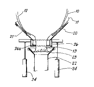
Figure l shows a vertical cross-section
through the equipment;
and Figure 2-5 show stages in the discharge of the
lo content~ of the container using the
equipment of Figure 1.
Referring now to the drawings it will be seen
that the container comprises an outer bag 10 of woven
polypropylene having a flap 11 closing its underside and
an inner liner 12 of polyethylene having a tubular
discharge spout 13 on its underside.
;.;' ' '
Turning now to Figure 1, the discharge equipment
comprises a shallow hopper 20 adapted to receive the ;~
lower end of the container. A door 21 gives access to
the interior of the hopper to enable the spout of the ~-
liner to be untied.
'..' :....

- 4 -
.~ ~3~ 7~
Beneath the hopper 20 is a fixed discharge duct ~ -:
22 having a frusto-conical mouth 23 at its upper end.
Reciprocable in a vertical direction above the :~
mouth 23 under the control of pneumatic actuating ~ ;
cylinders 24 is an annular spout section 26 of
cylindrical form having a circular resilient seal on its
lower edge and which in its lowered position sealingly
engages the internal upwardly directed surface of the
mouth 23.
~ , '
Means (not shown~ may be provided for vibrating
the hopper 20.
In use, a container is delivered to the vicinity
of the discharge e~uipment on a pallet P (Figure 2).
The container is suspended by loops 16 from a rigging
frame F and raised using a fork-lift truck to enable the
flap 11 to be pulled aside (Figure 3). The container is ~
lowered onto the hopper 20, and the spout 13 is untied :
and pulled down and arranged with an upturned cuff over
the mouth 23 (Figure 4). The spout section 26 is
lowered to clamp the spout 13 against the mouth 23 with
the cuff between the two relatively moveable parts ~:~
(Figure 5). Discharge is then effected, assisted if
necessary by vibrating hopper 20.
:'~
,~ ' ', '' . . ~ .' ''. ,. . " '' , '' . " ' ' ', '. ' . . "' ' . ,. " . ' ' . . ' '

- 5 - ~331574
entered the duct 21, will be retained in the upturned
cuff at the lower end of spout 13. ~-
, ~: . r.~
After raising spout section 26 the spout 13 can
be removed from mouth 23 without spilling any retained
material into duct 22.
. It will be appreciated that it is not intended
to limit the invention to the above example only, many
variations, such as might readily occur to one skilled
in the art, being possible, without departing from the ~ :
scope thereof as defined by the appended claims.
~:
- ' ;: . ,;
~': :. :'',.,
: -- ,:: -,

Representative Drawing
A single figure which represents the drawing illustrating the invention.
Administrative Status

2024-08-01:As part of the Next Generation Patents (NGP) transition, the Canadian Patents Database (CPD) now contains a more detailed Event History, which replicates the Event Log of our new back-office solution.

Please note that "Inactive:" events refers to events no longer in use in our new back-office solution.

For a clearer understanding of the status of the application/patent presented on this page, the site Disclaimer , as well as the definitions for Patent , Event History , Maintenance Fee  and Payment History  should be consulted.

Event History

Description Date
Time Limit for Reversal Expired 2005-08-23
Letter Sent 2004-08-23
Grant by Issuance 1994-08-23

Abandonment History

There is no abandonment history.

Fee History

Fee Type Anniversary Year Due Date Paid Date
MF (category 1, 3rd anniv.) - standard 1997-08-25 1997-07-14
MF (category 1, 4th anniv.) - standard 1998-08-24 1998-07-13
MF (category 1, 5th anniv.) - standard 1999-08-23 1999-07-15
MF (category 1, 6th anniv.) - standard 2000-08-23 2000-07-12
MF (category 1, 7th anniv.) - standard 2001-08-23 2001-07-11
MF (category 1, 8th anniv.) - standard 2002-08-23 2002-07-10
MF (category 1, 9th anniv.) - standard 2003-08-25 2003-07-16
Owners on Record

Note: Records showing the ownership history in alphabetical order.

Current Owners on Record
BAGFILLA OVERSEAS LIMITED
Past Owners on Record
BARRIE ARMSTRONG POULTON
Past Owners that do not appear in the "Owners on Record" listing will appear in other documentation within the application.
Documents

To view selected files, please enter reCAPTCHA code :


To view images, click a link in the Document Description column. To download the documents, select one or more checkboxes in the first column and then click the "Download Selected in PDF format (Zip Archive)" or the "Download Selected as Single PDF" button.

List of published and non-published patent-specific documents on the CPD .

If you have any difficulty accessing content, you can call the Client Service Centre at 1-866-997-1936 or send them an e-mail at CIPO Client Service Centre.


Document
Description 
Date
(yyyy-mm-dd) 
Number of pages   Size of Image (KB) 
Abstract 1995-08-28 1 44
Drawings 1995-08-28 3 87
Claims 1995-08-28 1 37
Descriptions 1995-08-28 5 202
Representative drawing 2002-01-15 1 8
Maintenance Fee Notice 2004-10-17 1 173
Fees 1999-07-14 1 28
Fees 1996-07-14 1 60
PCT Correspondence 1994-05-25 1 26
Examiner Requisition 1993-09-20 2 48
Prosecution correspondence 1992-05-28 1 22
Examiner Requisition 1992-02-03 1 46
Prosecution correspondence 1993-11-25 1 32