Note: Descriptions are shown in the official language in which they were submitted.
~333. 75~ ~:
~:
The present invention ralates to a variable displacement
type compressor and, more particularly, such a compressor
comprising a casing having a working chamber internally defined
therein and a plurality of cylinder bores provided therein opened
to face to the working chamber. A driving shaft is rotatably
carried in the casing with the cylinder bores axially aligned with
and disposed around the driving shaft. A working piston is
slidably received in each of the cylinder bores. A sleeve is
axially slidably fitted over the driving shaft within the working
chamber. A holder is carried on the sleeve for swinging movement
aboùt an axis perpendicular to an axis of the driving shaft and is
connected to the driving shaft. A swingable swash plate is carried
on the holder and is connected to the working pistons through
connecting rods. A control piston is connected to the sleeve and
slidably received in the casing so as to vary the angle of
inclination of the holder and the swingable swash plate to vary
the operation stroke of the working pistons. Stroke detecting
means is provided for detecting the operation stroke of the working
pistons.
~ A variable displacement type compressor is known, for
example, from Japanese Patent Application Laid-open No. 218670/87
or the like, in which the operation stroke of the working pistons
is varied by controlling the angle of inclination of a swash plate
swingable about an axis perpendicular to an axis of a driving
- ~
~ ~ 3 ~
shaft, and with the variation of the operation stroke, the
discharge amount is varied.
In such compressor, however, it is necessary to detect
the operation stroke of the working pistons for the purpose of
controlling the operation stroke of the working pistons and
detecting any trouble. In the above compressor, a position
detector is provided in the casing, which generates an electric
pulse signal whenever an object to be detected, provided on the
swingable swash plate passes through sensing range of the position
detector. In such a position detector for detecting the operation
stroke by detection of the swinging motion of the swingable swash
plate, however, the detection of the stroke is possible only when
the swingable swash plate is swung. The operation stroke cannot
be detected before starting of the operation of the compressor.
For this reason, when the operation of the compressor is started
in a region of slow speed (lower revolutions) of an engine
connected to the driving shaft (e.g., during idling), it is not
obvious that the number of revolutions of the engine should be set
at what level and in addition, it is impossible to set the amount
of fuel supplied to the engine sufficient to maintain the number
of revolutions.
The present invention provides a variable
displacement type compressor wherein the stroke of the
working pistons can be detected even before starting of the
operation of the compressor.
, ~....
~A
~ ~3~
A first feature of the invention resides in a variable
displacement type compressor comprising a casing having a working
chamber internally defined therein and a plurality of cylinder
S bores provided therein opened to face to the working chamber,
driving shaft rotatably carried in the casing with the cylinder
bores disposed around the driving shaft, a working piston slidably
received in each of the cylinder bores, a sleeve axially slidably
fitted over the driving shaft within the working chamber, a holder
carried on the sleeve for swinging movement about an axis
perpendicular to an axis of the driving shaft and connected to the
driving shaft, a swingable swash plate carried on the holder and
connected to the working pistons through connecting rods, a
control piston connected to the sleeve and slidably received in
the casing so as to vary the angle of inclination of the holder and
the swingable swash plate to vary the operation stroke of the
working pistons, and stroke detecting means for detecting the
operation stroke of the working pistons, wherein the stroke
detecting means comprises an interlocking member supported at its
middle portion on the casing through a support shaft having an axis
perpendicular to the axis of the driving shaft and connected at one
end thereof to the control piston, and a position detector disposed
on the casing to detect the position of the other end of the
; interiocking member.
25~ In addition, a second feature of the present invention
resides in that the control piston is relatively rotatably
:~ 3
' ~
` '
` i~i A
.~ .
.. ,,.- ~,.. ...... .................... .
, ~.. " .,, . ,-., ` - , ......... . . . .. . . .
11 ~33 7~
connected to the sleeve to inhibit the transmission of the rotating
movement of the sleeve about the axis of the driving shaft.
Further, a third feature of the present invention resides
in that the position detector is disposed outside the casing.
According to the first feature, the p~sition of the other
end of the interlocking member connected at one end thereof to the
control piston is determined depending upon the operation stroke
of the working pistons, i.e., the position of the control piston
along the axis of the driving shaft. Hence, the operation stroke
of the working pistons may be detected by detecti~g the position
of the other end of the interlocking member by the position
detector. Therefore, it is possible to detect the operations
stroke even before starting of the operation of the compressor.
For the other end of the interlocking member to be detected by the
position detector, it is desirable in improving the detection
accuracy that such other end i8 largely displaced as compared with
the axial displacement of the control piston, on the one hand, and
it is desirable in the layout of the detector that the amount of
such displacement is smaller, on the other hand. Thus, it is
possible to provide a design with these conflicting demands
satisfied by selection of the position at which the support shaft
of the interlocking member is disposed.
According to the second feature, the rotational movement
~ of the sleeve is inhibited from being transmitted to the control
piston and therefore, a force in the rotational direction being
applied to the interlocking member is avoided.
A
; .... . . .. .... . .
~. i.. . . ... . .. , ~.
... .. . ~ ~.. .
i7', ' ' . .
3 ~
Further, according to the third feature, it is possible
to replace and repair the parts of the position detector without
opening of the interior of the casing.
The present invention will become readily apparent
by reference to the following detailed description when
considered in conjunction with the accompanying drawings
wherein:
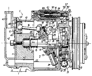
Figs. 1 and 2 illustrate one embodiment of the present -
invention, wherein
Fig. 1 is a side view in longitudinal section of an
essential portion of a variable displacement type compressor; and
Figure 2 is a front view of an interlocking member; and
Figure 3 is a side view in longitudinal section of
another embodiment of the position detector of the present
invention.
: ;'
The present invention will now be described by way of
embodiments with reference to the accompanying drawings. Referring
.0 first to Fig. 1 illustrating one embodiment of the present
invention, a variable displacement type compressor C is used for
compression of a refrigerant gas, for example, in an air
conditioner for a vehicle. A casing 1 for the compressor C is
comprised of a bottomed basically cylindrical casing body 2, a
` A
~;:
~ 33~,~,"i
cylinder block 3 secured to an opened end face of the casing body
2, and a cylinder head 4 superposed on an end face of the cylinder
block 3, which components are integrally connected. A working
chamber 5 is defined in the casing 1 by the caæing body 2 and the
cylinder block 3.
A driving shaft 6 is rotatably carried on the cylinder
block 3 in the casing 1 and on a closed end wall 21 of the casing
body 2 with radial needle bearings 7 and 8 interposed therebetween,
respectively. The axis of the driving shaft 6 lies on an axis Ll
of the casing 1. A drive pulley 9 with a clutch therein is
integrally connected to a projecting end of the driving shaft 6
projecting from the closed end wall 21 of the casing 1. The drive
pulley 9 is operatively connected to a drive source such as an
engine which is not shown, so that it may be rotatively driven by
a driving power from the engine.
The cylinder block 3 has a plurality of cylinder bores
10 provided therein in parallel to the driving shaft 6. Each bore
10 is opened at one end into the working chamber 5. These cylinder
bores 10 are disposed at distances equally spaced apart on a
~0 concentric circle about the axis Ll. An end plate 11 is clamped
between the cylinder head 4 and the cylinder block 3 to close the
other end of each of the cylinder bores 10. A working piston 13
is slidably received in each cylinder bore 10 to define a pressure
chamber 12 between it and the end plate 11. One spherical end of
a connecting rod 14 is rotatably connected to a back of each of the
working pistons 13 on the side of the working chamber 5, and the
:
~A
.: .:- ~. ., . :,,. . : . - .. :
:. . . -.~ ~:
, ~ ~ 3 3 7 I r
other spherical end of each of the connecting rods 14 reaches the
inside of the working chamber 5 and is connected to a swingable
swash plate 19 which will be described hereinafter.
In the working chamber 5, a sleeve 15 is slidably fitted
over the driving shaft 6. A pair of left and right pivots 16 are
integrally provided on the outer surface of the sleeve in
projection on lateral opposite sides of the sleeve 15 with each
having a center on an axis L2 perpendicular to the axis Ll of the
driving shaft 6 (normal to the sheet surface of Fig. 1) A board-
like holder 17 is carried on the left and right pivots 16 for
swinging movement back and forth along the axis of driving shaft
6. The swingable swash plate 19 is rotatably carried on a
cylindrical portion 171 of the holder 17 extending to surround the
sleeve 15. A radial bearing 18 is interposed between the
cylindrical portion and the swash plate. A needle thrust bearing
20 is interposed between opposed surfaces of the swingable swash
plate 19 and the holder 17. A detent member 21 is connected to an
outer end of the swingable swash plate 19 by a connecting pin 22.
A guide groove 23 is provided in an inner surface of the casing
0 body 2 extending in parallel to the driving shaft 6 between the
cylinder block 3 and the end wall 21 of the casing body within the ~-
working chamber S. The detent member 21 is slidably engaged in the
guide groove 23. The guide groove 23 and the detent member ~1
prevent the swingable swash plate 19 from rotating about the axis
Ll. -
The driving shaft 6 is integrally provided with a drive
~ ~ 3 ~
pin 25 projecting therefrom and having a radially extending axis.
The drive pin 25 has a connecting arm 26 integrally provided on its
leading end and having an arcuate hole 27 in which is slidably
engaged an pin 28 which is integrally provided on a mounting piece
172 of the holder 17 to project therefrom. The arcuate hole 27
permits the swinging movement of the swingable swash plate 19 about
the pivots 16 within an extent of its length, and the holder 17 is
rotated in response to rotation of the driving shaft 6.
The spherical ends of the connecting rods 14 connected
to the working pistons 13 are rotatably connected to one surface
of the swingable swash plate 19, as described above. Therefore,
the operation stroke, i.e., the discharge amount of the working
piston 13 in the cylinder bore 10 is determined depending upon the
angular displacement of the swingable swash plate 19 about of the
axis L2 of the pivots 16 relative to the axis Ll.
The driving shaft 6 is formed, at its end closer to the
cylinder block 3, wîth a smaller diameter shaft portion 62 through
a stepped portion 61~ A coiled compression spring 29 is wound
around the smaller diameter shaft portion 62. The coiled
compression spring 29 is engaged at one end thereof with a spring
seat 30 fitted and locked over the smaller diameter shaft portion
62, and at the other end thereof with an annular stopper 31 locked
over the stepped portion 61. The stopper 31 functions to engage
one end face of the sleeve 15 to compress the coiled compression
spring 29, when the sleeve 15 slides leftwardly as viewed in Fig.
1.
~A
.. . .~ ` , ` - .; `,
. . . .. . .
~ . . . . . .
.i . ~ , , , .,, . . ,, ~ ;.
. , ~ .. . .
1 3 3 1 ~ ~ ~
An annular bottomed slide bore 32 opened toward the
working chamber S is centrally provided in the end wall~21~) of the "
casing 2 in a concentric relation to the driving shaft 6. An
annular control piston 33 is slidably received in the slide bore
32. A control pressure chamber 34 is defined between the control
piston 33 and a closed end of the slide bore 32. A coiled
compression coiled spring 35 is contained in the control pressure
chamber 34 biasing the control piston 33 toward the working chamber
5.
The control piston 33 is rotatably carried at its end
closer to the working chamber 5 on a control plate 37 with angular
ball bearing 36 interposed therebetween. The control plate 37 is
integrally provided with a cylindrical portion 371 which axially
extends to surround the driving shaft 6 and has its end face
lS engaged with an end face of the sleeve 15 by a repulsive force of
the coiled compression spring 35. The cylindrical portion 371
also has an axially extending slit 38 made therein. The drive pin
25 extends through the slit 38, and the control plate 37 is rotated
in unison with the driving shaft 6 while pèrmitting the axial
movement of the control plate 37.
A thrust needle bearing 39 is interposed between a back
of the control plate 37 and the end wall 21 of the casing body 2.
If the control piston 33 sl`ides leftwardly or rightwardly, the
sleeve 15 axially moves following the control piston 33, and
correspondingly, the angular displacement of the holder 17 and the
.-; g
: r ~ .
~ 3 3 3 ~
swingable swash plate 19 about the pivots 16 varies. More
specifically, when the control piston 33 has moved leftwardly as
viewed in Fig. 1, the holder 17 and the swingable swash plate 29
are swung clockwisely in correspondence to the movement of the
control piston 33, resulting in a smaller sliding stroke of each
working piston 13. On the other hand, when the control piston 33
has moved rightwardly, the sleeve 15 also moves rightwardly under
the influence of a working pressure on the working pistons 13.
Correspondingly, the holder 17 and the swingable swash plate 19 are
swung conterclockwisely as viewed in Fig. 1 resulting in a larger
operating stroke of the working pistons 13.
A discharge chamber 42 is defined between the cylinder
head 4 and the end plate 11, and a discharge passage 43 provided
in the cylinder head 4 is connected to the discharge chamber 42.
An intake chamber 44 is defined between the cylinder head 4 and the
end plate 11 to angularly surround the discharge chamber 42 and is
connected to the working chamber 5 through a communication passage
45 made in the cylinder block 3. Further, an intake passage (not
shown) made in a wall of the casing body 2 is connected to the
working chamber 5.
The end plate 11 is provided with plural discharge ports
46 which permits the communication of the discharge chamber 42 with
the pressure chambers 12. A discharge valve 47 is mounted in each
discharge port 46 and adapted to open the discharge port 46 when
~25 the working piston 13 is in a compressing operation. The end plate
11 is further provided with plural intake ports 48 which permits
; ' '
~,
?.1 ;`
~.:
3 ~
the communication of the intake chamber 44 with the pressure
chambers 12. An intake valve 49 is mounted in each intake port 48
and adapted to open the intake port 48 when the working piston 13
is in an intake operation.
As the plurality of pistons 13 reciprocate in sequence,
in viewing the intake stroke- of a particular piston, the
refrigerant is passed from the intake passage through the working
chamber 5 and the communication passage 45 into the intake chamber
44 and then, it opens the corresponding intake valve 49 and is
drawn into the respective pressure chamber 12. In the compressing
stroke of the piston, the compressed refrigerant in the respective
pressure chamber 12 opens the corresponding discharge valve 47 and
is passed under pressure from the discharge chamber 43 into the
discharge passage 43.
A control valve 51 is disposed in the end wall 21 of the
casing body 21 in the casing 1 for providing the pressure control
for the control pressure chamber 34. The control value 51 is
interposed between a discharge passage (not shown) leading to the
discharge chamber 44 and an intake passage 52 leading to the intake
chamber 44 through the working chamber 4 and through the
communication passage 45, as well as a control passage 53 leading
to the control pressure chamber 34. The control valve 51 is
adapted to increase the pressure in the control pressure chamber
34 in response to the reduction of the pressure in the intake
chamber 44 when the cooling load of the air conditioner is reduced,
whereby the control piston 33 is moved leftwardly as viewed in Fig.
11
~ A
~333 ~
1, causing the holder 17 and the swingable swash plate to swing in
a righting direction, resulting in a smaller operation stroke of
each working piston 13, on the one hand, and to reduce the pressure
in the control pressure chamber 34 in response to the increase of
the pressure in the intake chamber 44 when such cooling load is
increased, whereby the control piston 33 is moved rightwardly as
viewed in Fig. 1 causing the holder 17 and the swingable swash
plate 19 to swing counterclockwisely as viewed in Fig. 1, resulting
in a larger operation stroke of each working piston 13, on the
other hand.
In order to detect the operation stroke of each working
piston 13, stroke detecting means 57 is disposed in the compressor
C and comprises an interlocking member S5 supported at its middle
portion on the casing l through a support shaft 54 parallel to the
~5 axis L2 and perpendicular to the axis Ll of the driving shaft 6 and
connected at one end thereof to the control piston 33, and a
position detector 56 disposed in the casing 1 to detect the
position of the other end of the interlocking member 55.
As shown in Fig. 2 the interlocking member 55 is
comprised of a semicircular portion 551 having a radius slightly
larger than that of an outer peripheral surface of the control
piston 33, a connecting plate portion 552 linked to a
circumferentially central portion of the semicircular portion 551~
i and a pair of opposed plate portions 553 and 553 perpendicularly
linked to the connecting plate portion 552 in an opposed relation.
Inwardly projecting pins 58 are mounted on circumferentially
12
` ~A
11 ~ 3 ~
opposite ends of the semicircular portion 551~ respectively and are
engaged in annular grooves 59 provided in an outer surface of the
control piston 33, respectively, whereby one end of the
interlocking member 55 is connected to the control piston 33.
Insert holes 71 are made in the opposed plate portions 553 and 553,
respectively, and the support sha~t 54 inserted through the insert
holes 71, 71 is supported on the casing 1, whereby the middle
portion of the interlocking member 55 is supported on the casing
1.
The position detector 56 is a differential transformer
and comprises a basically cylindrical housing 60, a bobbin 61
basically cylindrically formed of a synthetic resin and fixed
within the housing 60, secondary coils 62, 62 wound around an outer
periphery of the bobbin 61 at two axially spaced-apart places,
respectively, primary coils 63, 63 wound around outer peripheries
of the secondary coils 62, 62, respectively, a core axially movably
received in the bobbin 61, and a spring 65 interposed between the
bobbin 61 and the core 64 for biasing the core 64 axially outwardly
(rightwardly as viewed in Fig. 1). ~he housing 60 is fixed to the
outer surface of the casing body 2 in the casing 1 in a parallel
relation to the axis Ll of the driving shaft 6.
~ An opening 66 is provided in the casing body 2 at its
portion corresponding to the position detector 56, and an opening
67 is also provided in the housing 60 of the position detector 56
;~25 at its portion correspondlng to the opening 66. The other end of
the interlocking member 55 supported on the casing 1 by the support
. 13
.. ,,, . _ .. , . . , . ~ . . . . . ~ . ...
~3~7.~
shaft 54, i.e., the opposed plate positions 553, 553 are inserted
through the openings 66 and 67 into the housing 60 and disposed on
opposite sides of the bobbin 61. A connecting pin 68 is fixed to
an outer end of the core 64 to extend aldng one diametrical line
and has its opposite ends projecting outwardly through an elongated
hole 69 provided in the bobbin 61; The opposed plate portions 553,
553 are provided at leading ends thereof with substantially U-
shaped engagement portions 70, 70 with which opposed ends of the
connecting pin 68 are engaged, respectively.
With such stroke detecting means 57, when the axial
movement of the control piston 33 causes the interlocking member
55 to be swung about the support shaft 54, the core 64 is axially
displaced with the change in position of the other end of the
interlocking member 55, i.e., the leading ends of the opposed plate
portions 553, 553. In a condition of a rectangular-wave input
voltage having a given frequency and a given amplitude being
applied to the primary coils 63, 63, the difference in AC voltage
developed between the secondary coils 62, 62 is varied depending
upon the axial displacement of the core 64. Therefore, it is
possible to detect the axial position of the core 64, i.e., the
axial position of the control piston 33 through the interlocking
member 55.
The operation of this embodiment will be described below.
When the control piston 33 is moved axially, the sleeve 15 is moved
axially of the driving shaft 6 with the aid of the control plate
37. Correspondingly, the holder 17 and the swingable swash plate
14
A ~
19 are swung about the pivots 16, resulting in a varied operation
stroke of each working piston 13. Thus, the operation stroke of
the working pistons 13 corresponding to the axial position of the
control piston 33 can be detected by the pocition detector 56,
because the interlocking member 55 is also swung about the support
shaft 54 as the control piston 33 is moved.
Moreover, the position detector 56 detects the position
of the other end of the interlocking member 55 corresponding to
the axial position of the control piston 33 and is capable of
detecting the axial position of the control piston 33, i.e., the
operation stroke of the working pistons 13, even before the
variable displacement type compressor C is operated. Therefore,
the number of revolutions of the engine can be set, and the amount
of fuel supplied to the engine sufficient to maintain the number
of revolutions can be also set, both at the time when the operation
of the compressor C is started in a region of lower revolution of
the engine connected to the driving shaft 6.
For the position detector 56, it is desirable in
improving the detection accuracy that the core 64 is largely
displaced as compared with the axial displacement of the control
piston 33, on the one hand, and it is desirable in the layout of
the position detector 56 that the amount of such displacement is
smaller, on the other hand. However, it is possible to provide a
design with a balance of such conflicting demands taken by
selection of the disposing position for the support shaft 54
supporting the interlocking member 55.
- ` A
~.,.... .. ~ . ~ .
~........ . .
2~
~ ~3~
Further, an angular ball bearing 36 is interposed between
the control plate 37 and the control piston 33. Therefore, it is
avoided to the utmost that the rotational motions of the sleeve 15
and the control plate 37 influence the control piston 33, thereby
5avoiding the rotational operation of the control piston 33 to the
utmost. Thus, it is possible to prevent an unreasonable force from
being applied to one end of the interlocking member 55.
In addition, it is possible to replace and repair the
parts of the position detector 56 without opening of the casing 1,
10because the position detector 56 is disposed outside the casing 1.
Fig. 3 illustrates another embodiment of the present
invention, wherein portions corresponding to those in the previous
embodiment are designated by the same reference characters.
Stroke detecting means 57' is comprised of an
15interlocking member 55' connected at one end thereof to the control
piston 33 (Fig. 1) and swingably supported at its middle portion
on the casing 1 through the support shaft 54, and a position
detector 56' disposed on the casing 1 to detect the position of the
other end of the interlocking member 55'.
20The position detector 56' is a differential transformer
and comprises a housing 60' fixed to an outer surface of the casing
body 2 in the casing 1, a bobbin 61' fixed in the housing 60',
secondary coils 62', 62' wound around the bobbin 61' at two places
'spaced apart axially of the driving shaft 6 (see Fig. 1), i.e.,
25laterally as viewed in Fig. 3, a primary coil 63' wound around the
bobbin 61' at a place intermediate between the secondary coils 62', ~ -
,.::
16
`~ A :-
62', and a core 64' integrally provided on the other end of the
interlocking member 55' protruded through an opening 66 in the
casing body 2 into the housing 60'. The core 64' is disposed in
an opposed relation to the secondary coils 62', 62' and the primary
coil 63'.
With such stroke detecting means 57', the difference in
AC voltage developed between the secondary coils 62', 62' is varied
depending upon the swinging movement of the interlocking member 55'
about the support shaft 54. Therefore, it is possible to detect
the position of the other end of the interlocking member 55', and
to detect the operation stroke of the working pistons 13 (see Fig.
1), even before starting of the operation of the compressor C.
Thus, it is possible to provide an effect similar to that in the
previous embodiment.
The position detector 56, 56' has been shown and
described as a transformer in each of the above embodiments, but
may be any type of detector which is capable of detecting the
position of the other end of the interlocking member 55, 55'. For
example, a magnetic resistor element, a slide resistor or the like
can be used in place of the differential transformer to compose a
position detector.
As discussed above, according to the first feature of the
present invention, the stroke detecting means comprises an
' interlocking member supported at its middle portion on the casing
through a support shaft having an axis, perpendicular to the axis
; of the driving shaft and connected at one end thereof to the
17
~333 ~ Jj
control piston, and a position detector disposed on the casing to
detect the position of the other end of the interlocking member.
Therefore, it is possible to detect the operation stroke even
before starting of the operation of the compressor, thereby
S providing a design which satisfies requirements for the detection
accuracy and the layout of the position detector.
According to the second feature of the present invention,
the control piston is relatively rotatably connected to the sleeve
to inhibit the transmission of the rotating movement of the sleeve
about the axis of the driving shaft. Therefore, it is possible to
avoid the rotating operation of the control piston, thereby
preventing an unreasonable force from being applied to the
interlocking member.
Further, according to the third feature of the present
invention, the position detector is disposed outside the casing and
hence, replacement and repair the parts of the position detector
is facilitated.
~; A ~ ~