Note: Descriptions are shown in the official language in which they were submitted.
~33233~
1 21766-501
The invention relate~ to a laying nest for at least one
chicken or other type of egg-laying poultry, the laying nest being
provided with a floor which has a slight slope towards a
collecting device for the eggs laid by the poultry, over which
floor a iweeper mem~er can swing for removal of poultry from the
floor, which sweeper member is attached for pivoting to a shaft
extending above the floor in a horizontal plane. Such a laying
nest is known from, among others, the Dutch patent application
8204139. Such a laylng nest is formed such that during turning
out of the poultry a force ha~i to be applied permanently, which
can be experienced by the animals as very disturbing, while in ~;
addition dead or unwilling animals are removed by application of a -~
greater turning out force. The purpoæe of turning out the animals
is that they must be prevented from incubating the laid eggs~
Generally, the animals must be turned out of the laying nest in
the evening, after which they may re-enter the laying neEit ln the
mornlng.
The invention has for its ob~ect a laying neEit wherein
- turning out can be perforDed automatically and vlrtually without
checks belng neceEisary, for inEitance with automatically controlled
hydraulic, pneumatic or electrical means. ;;
The invention provldes laying nest for at least one
chicken or other type of egg-laying poultry, said laying nest
having a floor with a slight slope towards a collecting device for
eggs laid by the poultry, over which floor a sweeper member is
mounted to swing for removal of poultry from said floor, sald
sweeper member being attached to a pivotal shaft extending
horizontally above said floor and being coupled via spring meang
:
' $
2 1332331 21766-501
to an operating means that is movable between two stable, limiting
positions, in a first of which said sweeper member i8 urged by
said spring means to a first inactive rest position, and ln a
second of which said sweeper member i8 urged by æaid spring meanæ
to a second inactive rest position, movement of said operating
means to said second extreme position being effective to move said
sweeper to said second lnactive positlon through a swinging
movement such that any poultry that may be present on the floor is
sub~ected to a turning out force from sald sweeper member aæ a
result of the tensloning in said spring means caused by such
movement of sald operating means.
Use of the lnventlon ensures that the anlmalæ to be
turned out are subjected to only a comparatlvely llght turnlng out
force from the sweeper member, as a result of whlch they are
gradually forced off the floor. Each time that an animal changes
positlon to get rid of the unpleasant effect of the turning out
force the sweeper member will move slightly further in ltæ
swinging movement over the floor, resulting in the anlmals being
removed one by one from the floor. It will be apparent that the
swlnging movement must take place such that there 1~ no
posslbility of eggs, which may be present on the floor, being
damaged by the sweeper member. A practical embodiment displays
the feature that the shaft to which the sweeper member i8 attached
can be rotated by the operating meanæ between two llmltlng or
e~treme angular posltlonæ in whlch lt can be held ln place, for
example by frlctlon, and bears at least one projection. Arranged
between the projectlon and the sweeper member ls a draw sprlng,
the projectlon ln the first extreme poæitlon of the operatlng
' ~
~ g,?
-2a- 13 3 2 3 3 ~ 21766-S01
means belng positioned such that the draw spring pulls the sweeper
member into its first rest position, and the projection ln the
second extreme position of the operating means being po~ltloned
such that the draw sprlng pulls the sweeper member into it~ second
re~t position.
A preferred embodiment dlsplays the special feature that
the turning out force to be applled by the spring means is
in~ufflcient to shift a poultry animal from the floor. Hereby it
can in particular be achieved that a dead or unwilllng animal is
not turned out. Of importance ln this respect i8 also a variant
including signalling meanx for generating a warning signal in the
case where the sweeper member,
~
'
~:
:
~,;~'~
:
3 1332331
despite activation of the operating means, stands still in an
intermediate position. With this embodiment an operative can
take the necessary steps, particularly to remove a dead anim-
al.
A very simple embodiment displays the feature that the
shaft carries an operating handle.
An importan~ variant has the characteristlc that the
laying nest comprises a house with a passage opening and that
the sweeper member forces the poultry for turning out to and
through this passage opening.
At least one flexible sheet is preferably suspended on
the top edge of the passage opening to at least partially
cover the passage opening.
This flexible sheet has preferably a violet-like colour.
A violet colour has been found to stimulate the tranquility of
the animals and to draw the animals to the nests, æo that they
only lay eggs there and not in other places.
In a very simple embodiment, in which the laying nest
comprises a house, the shaft is mounted in holes arranged in
walls of the house.
. ~ , .
~ A preferred embotiment has the particular feature that
., .
the house possesses a second passage opening for passage of
lai~d eggs to the collecting device, to the upper edge of which
opening;is attached a flap. This prevents the animals belng
subJected to a draught, which is unpleasant for them, and
from~'destroying eggs lying on ~he collecting device by pecking
at them, since they are then withdrawn f~rom~v~ew. ~
A very simple embodiment is that in which the floor
comprises~a b~ase board having artificial 'turf~'laid on~;le. The
~floor~can in this way~be removed and cleaned very'simply.
In order to prevent animals occupying a position on the
house of a laying nest a variant can be employed~1n which~the
house possesses a roof with a ridge and that placed for pivot-
~ lng on this ridge is a gutter with a V-shaped cross section,
`~ 35 which gutter is forced by spring means to a rest position in
which the legs of the V are directed upward, whereby the
, ~
.`, "~
1332331
force to be applied by the spring means is insufficient to
allow the gutter to support a poultry animal. Very simple,
cheap and light is the embodiment in which the sweeper member
comprises trellis work.
If required multiple laying nests can be accommodated
in one house, or various laying nests, whether or not with a
house, can be linked with one another.
The automatic laying nest according to the invention
offers great labour saving compared to the known laying nests
referred to, because brood animals are pushed automatically
; from their nesting places.
With the laying nest as according to NL-A-8204139 the
animals have to be pushed off their nest during the day so
that the eggs can be picked up. With the nest according to
the invention this takes place in the evening, when the anim-
als are no longer laying eggs. The invention will now be
elucidated with reference to the drawing of several embodim-
ents. In~the drawing:
Fig. 1 shows a perspective view of two linked houses
with Laying nest according to the invention;
Fig. 2 is a partly perspective view of a laying nest in
doubl~e form;
~ ; Fig. 3 is a partly broken away, perspective view in
',f ~ which~a~hou8e with a laying nest as according to fig. 1 is
; ~ 25~ shown in more detail;
. . ~
Fig~. 4 6hows a ~;cross sectlon through the~house with
laying~nést às~ n;~the~f~i~gures 1 and~3;
Fig.~5 shows~the ~detail V as in fig. 4; and
^ ~ ` F~ig.~6~the~detail VI as in fig. 4.
;30~ F1g~ 6hows tw ~hous~es ~ 2,~ 1D~which~ re cated~
layi~ng~nes~ts~acc~ordi~ng to the invention~ onnect~ing~onto the~
hou6es 1, 2~is~a~c~ollecting dev~ce~ in ~the form of a~ c~onveyor~
Fig.~2 show6 an embodiment in which two houses~ 4~ 5
;35 ~ with~1sy1~ng~nests are ~placed on either slde of the~conveyoi~
. . .
~3323~1
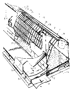
Fig. 3 shows the house 2 in more detail. House 2 compr-
ises vertical end walls 6, 7, a vertical rear wall 8 and a
sloping roof 9. A base board 10 of plywood, onto which is
laid artificial turf 11, is disposed at a slight slope, such
that eggs which are laid by animals sitting on the artificial
turf are gradually rolled through gravity and the movements
of the animals to conveyor belt 3, where they can be c`arried
away to a collecting station. Present for that purpose in the
lowest portion of the rear wall 8 is a passage opening 12
which is covered by a flap 13 to prevent draught.
Hanging from the lower edge oE the roof 9 is a flap 14
which is violet coloured. Thus is available a draught-free,
shady space that is pleasant for the animals.
Trellis work 15 can serve as sweeper member for turning
out the animals. The construction serving this purpose and
the operation of the invention will be explained hereinafter
with reference to the figures 4 and 5.
In the embodiment as according to fig. 3 the conveyor
.~, belt 3 iB covered by a roof 16.
) 20 All the parts described are made from Sendzimir galvan-
~ ,~, . . .
ized sheet steel. The stated houses are all formed as one
whole, as a result of which the houses can if require~d be
lifted up, for example with a winch construction (not~shown in
the~drawing) in~order~to reach the interior of the~iaying
25 ~nes~ts~ for instance for cleaning purposes.
In fig. 3 the direction of the active part of-thé conv-
eyor belt~ i;s~designatedi wi~h 17 and the direction of~ the
re~turn part with-~he~refer~ence numers1 18.
When performing~a swinging~movement for turn~ing~`~oùt ~
` 30 anlmals~the trellis work 15 cannot damage any eggs-that`~may
b~e present~on the~artificial t~urf 11, on the one~ hand~as ~a
ré~sult~of the`distance between one another of the ~bars~
extending in vertical planes, and on the other hand because
these bars are cove~red at their bottom end by saft caps 20.
r~e-~o~
6 1332331
~ -
The trellis work 15 is attached for pivoting to a shaft 21,
with respect to which reference is made to fig. 5, and is
mounted relative thereto by means of a bearing bush 22. Shaft
21 is mounted in holes 23 which are arranged in the vertical
end walls 6, 7. This mounting is such that the shaft can only
rotate when overcoming a certain friction force. Locking
means can also be present for securing the shaft in the two
extreme positions.
The shaft 21 bears projections 24. Arranged between each
projection 24 and trellis work 15 is a draw spring 25.
Attached to the outside end of shaft 21 for rotation of
same between two extreme positions is an operating handle 26.
It can be seen in fig. 4 that in the position of the
operating handle 26 indicated with drawn lines the draw spring
25 occupies a position such that it pulls the trellis work 15
to its first rest position indicated with drawn lines. This
~-~iK the position of the trellis work in which an animal 27 can
sit on the artificial turf 11 without being turned out. Should
an operative wish to turn out the animals 27, he then pulls
I ~
';~20 ~handle 26 over to the position indicated by 26', which is
~shown with~da~shed lines. As a result of the rotati~on ~of shaft
'~21'the pro~ect~ion 24 is~also rotated to the position lnd~icated
' w~ith~ 24', ~in which the~ spring 25 comes into~t~he~p~osition
`desig~nated~by-~25' locat~ed at the other side of the "swing~
o'ver~ point"~ Ko~ that ~the spring tension forceK~the~treIlis
work in the direction of the arrow 28 such that t~he a'nimal 27
is~Kob~'KctKd~ to' a turn1ng out force from the trèl` ~ work,
wh1~ch~s~ituat~1Qn;~'K~hown~with dashed~Iines~is desig~ ~ ' ~ ""1~5'~
The operating hanldle in this-~embodiment carl b~e;l`oc~ed~
30' ~in~-its~two~extreme~po~sitions~(-26, 26') by means~of~a locking
p~in~38~forming~part~of~loc~ing~member~s 36,~37.
Tur~ning out can be performed ~automatically~by-~meàns of
a~ time~clock~, whereby~for example a hydraul-ic, pneumatic~or
,~
r~,, .~ ',, ~ , . ... . .
-
~ 33233~
electrical driving is employed as force generating means.
Fig. 1 shows schematically signalling means 29 for emit-
ting a warning signal in the case where, despite operation of
the lever 26 as according to arrow 30 (see fig. 4), the trel-
lis work 15 stands still in an intermediate position, forexample the position 15', or at least a posit~on not corres-
ponding with the end rest position after displacement of the
trellis work as according to arrow 28. After such a rest
position has been reached, the animals can no longer enter
the laying nest. Only after resetting of the handle from
position 26' to position 26 is the laying nest again at the
disposal of the animals.
Finally, fig. 6 shows the ridge 30 of roof 9. The ridge
30 carries a gutter 31 having a V-shaped cross section which
is disposed for pivoting by means of a shaft 31 and a bearing
32, and which is forced by a spiral spring 33 to the rest
position shown in fig. 6. In this rest position the surfaces
34, 35 of gutter 31 are directed upward. The purpose of this
construction is to prevent animals taking up position on the
ridge 30 of the roof. As soon as they take up position on
gutter 31, a swinging over of the gutter must be carried out
80 that the animals do not find a stable surface on which to
rest. The force to be applied by the spring 33 must~t~he,refore
also be insufficient to allow the gutter 31 to support an
anima~l 27.~
A laying nest according to the invention pr~eferably
takes a Du~ltip1e form. A chicken is a com-unity~-an1mal -and
likes to lay eg,gs in a communal space.
I
I ~
~ ~ .
X ~