Language selection

Search

Patent 1332827 Summary

Third-party information liability

Some of the information on this Web page has been provided by external sources. The Government of Canada is not responsible for the accuracy, reliability or currency of the information supplied by external sources. Users wishing to rely upon this information should consult directly with the source of the information. Content provided by external sources is not subject to official languages, privacy and accessibility requirements.

Claims and Abstract availability

Any discrepancies in the text and image of the Claims and Abstract are due to differing posting times. Text of the Claims and Abstract are posted:

  • At the time the application is open to public inspection;
  • At the time of issue of the patent (grant).
(12) Patent: (11) CA 1332827
(21) Application Number: 1332827
(54) English Title: HEAVY DUTY CARRYING HANDLE FOR A CAN CARTON
(54) French Title: POIGNEE RESISTANTE POUR EMBALLAGE CARTON DE CONTENANTS METALLIQUES
Status: Expired and beyond the Period of Reversal
Bibliographic Data
(51) International Patent Classification (IPC):
  • B65D 5/46 (2006.01)
  • B65D 71/00 (2006.01)
(72) Inventors :
  • WOOD, PRENTICE J. (United States of America)
(73) Owners :
  • MEADWESTVACO PACKAGING SYSTEMS LLC
(71) Applicants :
  • MEADWESTVACO PACKAGING SYSTEMS LLC (United States of America)
(74) Agent: SMART & BIGGAR LP
(74) Associate agent:
(45) Issued: 1994-11-01
(22) Filed Date: 1989-09-22
Availability of licence: N/A
Dedicated to the Public: N/A
(25) Language of filing: English

Patent Cooperation Treaty (PCT): No

(30) Application Priority Data:
Application No. Country/Territory Date
249,115 (United States of America) 1988-09-26

Abstracts

English Abstract


A heavy duty carrying handle for a can carton formed
from a unitary blank and which includes interconnected bottom,
top and side walls together with end closure structure and
wherein the top wall is of double ply construction having
inner and outer panels, the handle having a transverse
elongated opening formed in the inner panel and having spaced
apart side edges, a pair of transverse fold lines formed in
the outer panel in near coincidence with the side edges of the
transverse elongated opening, a pair of transverse handle
flaps struck from the outer panel. and respectively joined
thereto along the transverse fold lines, the transverse handle
flaps having coincidental transverse edges defined by a
transverse perforated slit along which the handle flaps are
separable to accommodate inward folding of the handle flaps
through the transverse elongated opening.


Claims

Note: Claims are shown in the official language in which they were submitted.

THE EMBODIMENTS OF THE INVENTION IN WHICH AN EXCLUSIVE
PROPERTY OR PRIVILEGE IS CLAIMED ARE DEFINED AS FOLLOWS:
1. A carrying handle for a carton formed from a
unitary blank for packaging a plurality of cans and having
interconnected single ply bottom and side walls and a double
ply top wall having inner and outer panels together with end
closure panels, said handle comprising a transverse elongated
opening formed in said inner panel and having spaced apart
side edges, a pair of transverse fold lines formed in said
outer panel in near coincidence with said side edges of said
transverse elongated opening, a pair of transverse handle
flaps struck from said outer panel and respectively joined
thereto along said transverse fold lines, said transverse
handle flaps having coincidental transverse edges defined by a
transverse perforated slit along which said handle flaps are
separable to accommodate inward folding of said handle flaps
through said transverse elongated opening.
2. A carrying handle according to claim 1 wherein
each end edge of each of said handle flaps is defined by a
part of an aperture formed in said outer panel.
3. A carrying handle according to claim 2 wherein
each of said apertures is of circular configuration.
4. A carrying handle according to claim 3 wherein
each end portion of said transverse elongated opening is of
semi circular configuration and disposed in near coincidence
with the adjacent one of said circular apertures.
5. A carrying handle according to claim 1 wherein
said side edges of said elongated opening are spaced apart by
a distance slightly greater than the distance between said
transverse fold lines.
6. A carrying handle according to claim 1 wherein
coincidental perforated slits are formed in said outer and
said inner panels adjacent and normal to the side edges of
said top wall and arranged in substantially coaxial relation

to said transverse perforated slit.
7. A carrying handle according to claim 6 wherein
each of said coincidental perforated slits includes an
extension which is continued into the associated single ply
side wall.
8. A carrying handle according to claim 7 wherein a
pair of fold lines are formed in each of said side walls and
extend from the extremity of each of said extensions to the
adjacent carton corner between said top wall and the
associated side wall.

Description

Note: Descriptions are shown in the official language in which they were submitted.


-
- 1332827
HEAVY DUTY CARRYING HANDLE FOR A CAN CARTON
TECHNICAL FIELD
This invention relates generally to can cartons and
more particularly to heavy duty carryi~g handles for such
cartons.
BACKGROUND ART
U. S. patent number 4,558,816 issued December 17,
1985 and owned by the assignee of this invention discloses a
can carton in which a pair of handle panels are struck from
one carton wall and whose adjacent edges are coincidental with
a transverse perforated slit extending across the one carton
wall and having end projections extending into the carton
walls foldably joined with the one carton wall.
DISCLOSURE OF THE INVENTION
Accordlng to this invention in one form, a heavy
duty carrying handle is provided for a can carton which is
formed from a unitary blank and which includes interconnected
bottom, side and top walls together with end closure panels,
the top wall being of a double ply construction and the handle
comprising a transverse elongated opening formed in the inner
panel and having spaced apart side edges, a pair of transverse
fold lines formed in the outer panel! in near coincidence with
the side edges of said transverse elongated opening, a pair of
transverse handle flaps struck from said outer panel and
respectively joined thereto along said transverse fold lines,
said transverse-handle flaps having coincidental transverse
edges defined by a transverse perforated slit along which said
handle flaps are separable to accommodate inward folding of
said handle flaps through said transverse elongated opening.
BRIEF DESCRIPTION OF THE DRAWINGS
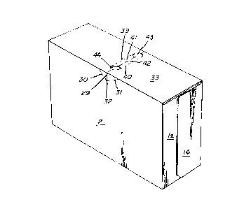
In the drawings, FIG. 1 is a perspective view of a
loaded set up can carton which embodies the heavy duty handle
structure of this invention; FIG. 2 is a plan view of the
blank from which the carton of FIG. 1 is formed, the blank

13~28~7
being shown with its inner surface up; FIG. 3 is a view of the
blank shown in FIG. 2 following its initial gluing operation
as performed by the carton manufacturer; and FIG. 4 is a
fragmentary plan view of a portion of the top wall of the
carton and which shows a preferred relationship between the
handle structure formed in the outer and inner plys of the top
wall.
BEST MODE OF CARRYING OUT THE INVENTION
With reference to FIG. 2 the numeral 1 designates
the bottom wall of the carton. Side wall;2 is foldably joined
to bottom wall 1 along fold line 3 and s;ide wall 4 is foldably
joined to bottom wall 1 along fold line 5.
An end flap 6 is foldably joined to bottom wall 1
along a fold line 7 and an end flap 8 is foldably joined to
bottom wall 1 along fold line 9. End wall panel 10 is
foldably joined to side wall 2 along a fold line 11 and end
wall panel 12 is foldably joined to side wall 2 along fold
line 13. End wall panel 14 is foldably joined to side wall 4
along fold line 15 and end panel 16 is foldably joined to side
wall 4 along fold line 17.
Known frangible tear structure is formed in side
wall 4 as is indicated by the arrow 18.
In accordance with this invention, the top wall of
the carton is of double ply str~cture and includes inner panel
25 19 which is foldably joined to side wall 2 along fold line 20.
A transverse elongated opening is designated by the arrow 21
and includes transverse spaced side edges 22 and 23. End
edges of transverse elongated opening 21 are designated at 24
and 25 and are of semicircular configuration. A perforated
30 slit 26 extends from end 24 of transverse elongated opening 21
to the side edge 27 of inner panel l9. Similarly a transverse
perforated slit 28 extends from end portion 25 of transverse
elongated opening 21 to the side edge 20 of inner panel 19. A
slit extension 29 is formed in side wall 2. Fold lines 30

.-- --
1332827
and 31 extend from the end 32 of slit extension 29 to the fold
line 20 between side wall 2 and inner top wall panel 19.
Outer top wall panel 33 is foldably joined to side
wall 4 along fold line 34. An end flap 35 is foldably joined
to outer top wall panel 33 along fold line 36 and end flap 37
is foldably joined along fold line 38 to the opposite end of
outer top wall panel 33.
Also formed in outer panel 33 are a pair of
transverse fold lines 39 and 40. A trànsverse handle flap 41
is foldably joined to outer panel 33 a~ong fold line 39 and
transverse handle flap 42 is foldably joined to outer panel 33
along fold line 40. A pair of apertures 43 and 44 are formed
in outer panel 33 and preferably are of circular
configuration. These apertures 43 and 44 define the end edges
of handle flaps 41 and 42 as is obvious from FIG. 2. A
transverse perforated slit 45 -defines coincidental edges of
handle flaps 41 and 42. Inward folding of one or both handle
flaps causes separation of the coincidental edges of handle
flaps 41 and 42 to accommodate inward folding of the handle
flaps. A transverse perforated slit 26a is formed in outer
panel 33 and is coaxially disposed relative to transverse
perforated slit 45. Similarly perforated transverse slit 28a
is formed in outer panel 33 and is coaxially disposed relative
to transverse perforated slit 45. Formed in side wall 4 is an
extension 47 of perforated slit 26a. A pair of fold lines 48
and 49 extend from the extremity 50 of extension 47 in angular
relation to the fold line 34.
In order to complete manufacture of the carton by
the carton manufacturer, an application of glue is applied to
the inner surface of outer top wall panel 33 as indicated in
FIG. 2 by stippling on that panel. Thereafter side wall panel
2 together with inner top wall panel 19 are elevated and
folded toward the right along fold line 3. Outer top wall
panel 33 is then elevated and folded to the left along fold

1332827
line 34. This operation secures inner panel 19 and outer
panel 33 in face contacting relation to form a double
thickness top wall for the carton. This operation establishes
coincidental fold lines by bringing the perforated transverse
slit 26 into coincidence with the perforated transverse slit
26a and also causes the transverse perforated slit 28 to come
into coincidence with the transverse perforated slit 28a.
These coincidental slits are coaxially disposed relative to
the perforated transverse slit 4S formed in outer top panel
33.
The carton as s~own in FIG. 3 is then shipped by the
carton manufacturer to the packager of cans who simply sets up
the carton with its ends open through which cans are loaded
from both ends. Thereafter the end panels such as 10, 12, 14
and 16 and the end flaps such as 6, 8, 35 and 37 are
manipulated into end closing positions and secured in such
positions by adhesive in known manner so that the carton when
fully loaded appears as shown in FIG. 1.
In order to transport the carton shown in FIG. 1, it
is simply necessary to depress the handle flaps 41, 42 and to
fold those flaps inwardly.
While the ends such as 24 and 25 of the elongated
opening 21 are in near coincidence with the adjacent portions
of apertures 43 and 44, the fold lines 39 and 40 may be in
near coincidence with the side edges 22 and 23 of elongated
transverse opening 21, although it is preferable to space
these elements, as shown in FIG. 4, i.e., with transverse fold
lines 39 and 40 spaced inwardly somewhat from the side edges
22 and 23 of elongated transverse opening 21.
INDUSTRIAL APPLICABILITY
From the above description, it is apparent that a
heavy duty handle structure is provided for a can carton which
is particularly well suited for heavy carton loads. For
example filled 12 ounce cans can be well accommodated by a
\
`\

, 1332827
-
carton with the heavy duty handle structure of this invention
where as many as 30 or m~re pri~ary can packages are disposed
within the can carton.
.,
. .
-

Representative Drawing
A single figure which represents the drawing illustrating the invention.
Administrative Status

2024-08-01:As part of the Next Generation Patents (NGP) transition, the Canadian Patents Database (CPD) now contains a more detailed Event History, which replicates the Event Log of our new back-office solution.

Please note that "Inactive:" events refers to events no longer in use in our new back-office solution.

For a clearer understanding of the status of the application/patent presented on this page, the site Disclaimer , as well as the definitions for Patent , Event History , Maintenance Fee  and Payment History  should be consulted.

Event History

Description Date
Time Limit for Reversal Expired 2008-11-03
Letter Sent 2007-11-01
Inactive: IPC from MCD 2006-03-11
Letter Sent 2004-06-09
Inactive: Office letter 2004-02-04
Grant by Issuance 1994-11-01

Abandonment History

There is no abandonment history.

Owners on Record

Note: Records showing the ownership history in alphabetical order.

Current Owners on Record
MEADWESTVACO PACKAGING SYSTEMS LLC
Past Owners on Record
PRENTICE J. WOOD
Past Owners that do not appear in the "Owners on Record" listing will appear in other documentation within the application.
Documents

To view selected files, please enter reCAPTCHA code :


To view images, click a link in the Document Description column. To download the documents, select one or more checkboxes in the first column and then click the "Download Selected in PDF format (Zip Archive)" or the "Download Selected as Single PDF" button.

List of published and non-published patent-specific documents on the CPD .

If you have any difficulty accessing content, you can call the Client Service Centre at 1-866-997-1936 or send them an e-mail at CIPO Client Service Centre.


Document
Description 
Date
(yyyy-mm-dd) 
Number of pages   Size of Image (KB) 
Representative drawing 2002-01-17 1 6
Description 1994-11-01 5 177
Abstract 1994-11-01 1 28
Claims 1994-11-01 2 61
Cover Page 1994-11-01 1 18
Drawings 1994-11-01 2 35
Maintenance Fee Notice 2007-12-13 1 173
Correspondence 2004-02-04 2 18
Fees 1996-10-15 1 54
Prosecution correspondence 1992-09-11 1 37
Examiner Requisition 1992-05-21 1 62
PCT Correspondence 1994-08-15 1 43