Note: Descriptions are shown in the official language in which they were submitted.
1333~8
MARINE PROPULSION DEVICE LOW LIQUID
PRESSURE WARNING SYSTEM
BACKGROUND OF THE INVENTION
The invention relates to warning
systems for internal combustion engines, and, more
particularly, to warning systems sensitive to engine
liquid pressures.
The desirability of monitoring engine
operating conditions and of providing means to warn
the operator of conditions hazardous to the engine or
to the operator are known. Many known warning
systems require an energy source independent of the
engine for operation of the warning means.
Attention is directed to the following
U.S. Patents:
Name Patent No. Date
Furukawa 4,695,822 September 22,1987
Monigold 4,526,140 July 2, 1985
Baltz 4,484,767 December 4, 1984
Monigold 4,485,287 November 20, 1984
Davis 4,278,056 July 14, 1981
Davis 4,126,114 November 21, 1978
Mills 4,117,822 October 3, 1978
Sliger 4,029,074 June 14, 1977
Fox 3,595,262 July 27, 1971
Goodwin 3,590,798 July 6, 1971
Goodwin 3,202,143 August 24, 1965
SUMMARY OF THE INVENTION
The invention provides a marine
propulsion device comprising a propulsion unit
including a propeller shaft adapted to support a
propeller, and an internal combustion engine
-2- 133~ IS8
drivingly connected to the propeller shaft, the
engine including a cavity adapted to house a liquid
under pressure, a source of gas at a pressure
different from atmospheric pressure, pneumatic
warning means for producing a warning signal in
response to communication between the source of gas
and the warning means, and valve means for permitting
communication between the source of gas and the
warning means when the liquid pressure is below a
specified value and for preventing communication
between the source and the warning means when the
liquid pressure is above the specified value.
The invention also provides an engine
apparatus comprising an internal combustion engine
including a cavity adapted to house a liquid under
pressure, a source of gas at a pressure different
from atmospheric pressure, pneumatic warning means
for producing a warning signal in response to
communication between the source of gas and the
warning means, and valve means for permitting
communication between the source of gas and the
warning means when the pressure of the liquid is
below a specified value and for preventing
communication between the source and the warning
means when the pressure of the liquid is above the
specified value.
The invention also provides a marine
propulsion device comprising a propulsion unit
13331~
--3--
including a propeller shaft adapted to support a
propeller, and an internal combustion engine
drivingly connected to the propeller shaft, the
engine including a cavity adapted to house a liquid
under pressure, a source of gas at a pressure
different from atmospheric pressure, pneumatic
warning means for producing a warning signal in
response to communication between the source of gas
and the warning means, a cylinder defining a cylinder
bore and having therein a passageway communicating
with one of the source and the warning means and
being communicable with the bore, a piston dividing
the cylinder into first and second chambers, the
first chamber communicating with the other of the
source and the warning means and being communicable
with the passageway, and the second chamber
communicating with the cavity, and valve means for
permitting opening of the passageway to the first
chamber in response to movement of the piston in the
direction m;n;m; zing the volume of the second
chamber, and for preventing opening of the passageway
to the first chamber in response to movement of the
piston in the direction minimizing the volume of the
first chamber.
The invention also provides a marine
propulsion device comprising a propulsion unit
including a propeller shaft adapted to support a
propeller, and an internal combustion engine
drivingly connected to the propeller shaft and
133~8
-3A-
including a cooling jacket adapted to contain coolant
under pressure, means for providing gas at a pressure
different from atmospheric pressure, pneumatic
warning means for producing a warning signal in
response to communication between the gas providing
means and the warning means, valve means movable
between a first position permitting communication
between the gas providing means and the warning means
when the pressure of the coolant is below a specified
value and a second position preventing communication
between the gas providing means and the warning means
when the pressure of the coolant is above the
specified value, and a spring biasing the valve means
toward the first position.
The invention also provides an engine
apparatus comprising an internal combustion engine
including a cooling jacket adapted to contain coolant
under pressure, means for providing gas at a pressure
different from atmospheric pressure, pneumatic
warning means for producing a warning signal in
response to communication between the gas providing
means and the warning means, and valve means for
permitting communication between the gas providing
means gas and the warning means when the pressure of
the coolant is below a specified value and for
preventing communication between the gas providing
means and the warning means when the pressure of the
coolant is above the specified value.
The invention also provides a marine
13~3~5~3
-3B-
propulsion device comprising a propulsion unit
including a propeller shaft adapted to support a
propeller, and an internal combustion engine
drivingly connected to the propeller shaft and
including a cooling jacket adapted to contain coolant
under pressure, means for providing gas at a pressure
different from atmospheric pressure, pneumatic
warning means for producing a warning signal in
response to communication between the gas providing
means and the warning means, a cylinder defining a
cylinder bore, a passageway communicating with one of
the gas providing means and the warning means, a
piston dividing the cylinder bore into a first
chamber communicating with the other of the gas
providing means and the warning means and being
communicable with the passageway, and a second
chamber communicating with the cooling jacket, valve
means for affording communication of the passageway
with the first chamber in response to movement of the
piston in the direction minimizing the volume of the
second chamber, and for preventing communication of
the passageway with the first chamber in response to
movement of the piston in the direction min;mi zing
the volume of the first chamber, and a spring located
in the first chamber and biasing the piston in the
direction minimizing the volume of the second
chamber.
The invention also provides a marine
propulsion device comprising a propulsion unit
1333~58
-3C-
including a propeller shaft adapted to support a
propeller, and an internal combustion engine
drivingly connected to the propeller shaft and
including a cavity adapted to house a liquid under
pressure, means for providing gas at a pressure
different from atmospheric pressure, pneumatic
warning means for producing a warning signal in
response to communication between the gas providing
means and the warning means, a cylinder defining a
cylinder bore, a passageway communicating with one of
the gas providing means and the warning means, a
piston dividing the cylinder bore into a first
chamber communicating with the other of the gas
providing means and the warning means and being
communicable with the passageway, and a second
chamber communicating with the cavity, and valve
means for affording communication of the passageway
with the first chamber in response to movement of the
piston in the direction m;nimi zing the volume of the
second chamber, and for preventing communication of
the passageway with the first chamber in response to
movement of the piston in the direction minimi zing
the volume of the first chamber, which valve means
includes a valve seat, a valve member movable into
and out of engagement with the valve seat for
respectively preyenting communication and affording
communication with the passageway, means for biasing
the valve member toward the valve seat when the
volume of the first chamber is greater than a
1 ~ 3 3 '~
-3D-
predetermined volume, and means for moving the valve
member into engagement with the valve seat when the
volume of the first chamber is less than or equal to
the predetermined volume.
The invention also provides a marine
propulsion device comprising a propulsion unit
including a propeller shaft adapted to support a
propeller, and an internal combustion engine
drivingly connected to the propeller shaft and
including a cooling jacket adapted to contain coolant
under pressure, means for providing gas at a pressure
different from atmospheric pressure, pneumatic
warning means for producing a warning signal in
response to communication between the gas providing
means and the warning means, valve means for
permitting communication between the gas providing
means and the warning means when the pressure of the
coolant is below a specified value and for preventing
communication between the gas providing means and the
warning means when the pressure of the coolant is
above the specified value, and a spring biasing the
valve means so as to permit commnnication between the
gas providing means and the warning means.
The invention also provides a marine
propulsion device comprising a propulsion unit
including a propeller shaft adapted to support a
propeller, and an internal combustion engine
drivingly connected to the propeller shaft and
1 3 3 3 ~ J? ~
--4--
including a cooling jacket adapted to contain coolant
under pressure, means for providing gas at a pressure
different from atmospheric pressure, pneumatic
warning means for producing a warning signal in
response to communication between the gas providing
means and the warning means, and valve means for
permitting communication between the gas providing
means and the warning means when the pressure of the
coolant is below a specified value and for preventing
communication between the gas providing means and the
warning means when the pressure of the coolant is
above the specified value.
The invention also provides a marine
propulsion device comprising a propulsion unit
including a propeller shaft adapted to support a
propeller, and an internal combustion engine
drivingly connected to the propeller shaft and
including a cooling jacket adapted to contain coolant
under pressure, means for providing gas at a pressure
different from atmospheric pressure, pneumatic
warning means for producing a warning signal in
response to communication between the gas providing
means and the warning means, a cylinder defining a
cylinder bore, a passageway communicating with one of
the gas providing means and the warning means, a
piston dividing the cylinder bore into a first
chamber com~unicating with the other of the gas
providing means and the warning means and being
communicable with the passageway, and a second
13334~;~
chamber communicating with the cooling jacket, and
valve means for affording communication of the
passageway with the first chamber in response to
movement of the piston in the direction mi n; mi zing
the volume of the second chamber, and for preventing
communication of the passageway with the first
chamber in response to movement of the piston in the
direction minimi zing the volume of the first chamber.
Other features and advantages of the
invention will become apparent to those skilled in
the art upon review of the following detailed
description, claims and drawings.
DESCRIPTION OF THE DRAWINGS
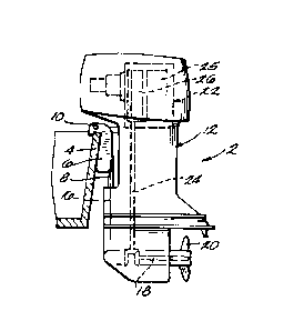
Figure 1 is a side view of a marine
propulsion device embodying various features of the
invention and including an apparatus for detecting a
low liquid pressure condition in an internal
combustion engine.
Figure 2 is a side view, partially in
section, of the apparatus including a pressure
sensitive valve means in a first position wherein the
pressure is not low and a pneumatic horn is not in
communication with the crankcase.
Figure 3 is a cross-sectional view of
the valve means in a second position wherein the
pressure is low and the pneumatic horn is in
communication with the crankcase.
l 333~
Figure 4 is a cross-sectional view of
the valve means in a third position wherein the
pressure is low and the pneumatic horn is not in
communication with the crankcase.
Before at least one embodiment of the
invention is explained in detail, it is to be
understood that the invention is not limited in its
application to the details of construction and the
arrangement of the components set forth in the
following description or illustrated in the drawings.
The invention is capable of other embodiments and of
being practiced or carried out in various ways.
Also, it is to be understood that the phraseology and
terminology employed herein is for the purposes of
description and should not be regarded as limiting.
DESCRIPTION OF THE PREFERRED EMBODIMENT
A marine propulsion device 2 embodying
the invention is illustrated in the drawings.
The marine propulsion device 2
comprises mounting means adapted to be mounted on the
transom 4 of a boat. While various suitable mounting
means can be employed, in the preferred embodiment,
the mounting means includes a transom bracket 6
mounted on the transom 4. The mounting means also
includes a swivel bracket 8 mounted on the transom
bracket 6 for pivotal movement relative to the
1 3 ~
--7--
transom bracket 6 about a generally horizontal tilt
axis 10.
The marine propulsion device 2 also
comprises a propulsion unit 12 mounted on the swivel
bracket 8 for pivotal movement relative thereto about
a generally vertical steering axis 16. The
propulsion unit 12 includes a propeller shaft 18
rotatably supporting a propeller 20, and an internal
combustion engine 22 drivingly connected to the
propeller shaft 18 via a conventional drive train 24.
The internal combustion engine 22 is preferably a
two-cycle engine having a water jacket 25 and a
crankcase 26, the crankcase 26 providing a zone of
alternating high and low pressures. The internal
combustion engine 22 also includes (see Figs. 2-4) a
wall 27 defining a cavity adapted to house a fluid
under pressure. The cavity is preferably the water
jacket 25. As shown in Figure 2, the wall 27 has
therein a cavity bore 28.
The marine propulsion device 2 also
includes a source of gas with a pressure different
from atmospheric pressure. In the preferred
embodiment, the source of gas includes the crankcase
26 (Fig. 1) of the internal combustion engine 22.
The marine propulsion 2 also includes
(see Fig. 2) pneumatic warning means 30 for producing
a warning signal in response to communication between
the crankcase 26 and the warning means 30. While
-8- ~333~8
various suitable pneumatic warning means can be
employed, in the preferred embodiment, the pneumatic
warning means 30 is a whistle.
The marine propulsion device 2 also
includes valve means 32 for permitting communicati~n
between the crankcase 26 and the warning means 30
when the liquid pressure in the water jacket 25 is
below a specified value and for preventing
communication between the crankcase 26 and the
warning means 30 when the liquid pressure is above
the specified value. While various suitable valve
means may be employed, in the preferred embodiment,
the valve means 32 includes a cylinder 34 defining a
cylinder bore 36 communicating with the water jacket
25. In the illustrated construction, cylinder 34 has
a right end that is threaded into the cavity bore
28. The cylinder 34 also has therein a passageway 38
communicating between the cylinder bore 36 and the
crankcase 26 and communicable with the warning means
30 as described below. The cylinder 34 also ha-s an
end wall 44 having thereon a spherical valve seat
46. The valve seat 46 defines an opening to a
passageway 47 which communicates with the warning
means 30 and which is communicable with the cylinder
bore 36 as described below.
The valve means 32 also includes a
piston 48 which is slidably housed by the cylinder 34
and which has thereon an o-ring 49 such that the
9 1 333~S8
piston 48 sealingly engages the cylinder 34. The
piston 48 has an end 50 (best shown in Fig. 4) facing
the end wall 44 and having therein a recess 51. The
piston 48 divides the cylinder bore 36 into a first
or left chamber 52 and a second or right chamber 56.
The first chamber 52 is located between the piston 48
and the end wall 44, and the second chamber 56 is
located between the piston 48 and the water jacket
25. The valve means 32 also includes stop means for
preventing the piston 48 from entering the water
jacket 25. While various suitable stop means can be
employed, in the preferred embodiment, such stop
means includes, in the cylinder 34, a step 60 which
is located in the second chamber 56 and which is
engageable with the piston 48, as shown in Figures 3
and 4. Preferably, the step 60 is defined by an
annular member 61 fixed axially of the cylinder 34 by
a set screw 62.
The valve means 32 also includes a
generally spherical ball valve member 68 which is
located in the first chamber 52 and which is movable
into and out of sealing engagement with the valve
seat 46 for respectively closing and opening the
passageway 47 to the first chamber 52. The valve
means 32 also includes a ball carrier 73 located in
the first chamber 52 and adapted to hold the ball
valve member 68. In the illustrated construction,
the ball carrier 73 has therein a recess 75 having a
1333458
--10--
spherical section and facing the valvel-seat 46 for
holding the ball valve member 68. The ball carrier
73 also has therein a recess 77 facing the piston
recess 51.
The valve means 32 also includes means
for biasing the piston 48 away from the end wall 44
or in the direction minimizing the volume of the
right chamber 56. While various suitable biasing
means can be employed, in the preferred embodiment,
such means includes a piston return spring 80
extending between the end wall 44 and the piston 48
such that the spring 80 biases the piston 48 towards
the stop means 60.
The valve means 32 also includes means
for biasing the ball valve member 68 toward the valve
seat 46 when the volume of the chamber 52 is greater
than a predetermined volume (the volume shown in Fig.
2). While various suitable biasing means can be
employed, in the preferred embodiment, such means
includes a ball member spring 82 partially housed by
the piston recess 51 and the ball carrier recess 77
such that the ball member spring 82 biases the ball
carrier 73 and the valve member 68 towards the valve
seat 46 and biases the piston 48 towards the stop
means 60.
As illustrated in Figure 2, during
normal operation of the engine 22, the valve means 32
is closed, not allowing communication between the
-11- 13334~8
crankcase 26 and the warning means 30. During normal
operation of the engine 22, the pressure exerted
against the piston 48 by the liquid housed in the
cavity 25 biases the piston 48 to the left or toward
the end wall 44 and against the piston return spring
80, thereby minimizing the volume of the first
chamber 52. The piston end 50 engages the ball
carrier 73 and forces the ball valve member 68
against the valve seat 46 to close off the passageway
47 between the crankcase 26 and the pneumatic warning
means 30. Thus, the piston 48 and the ball carrier
73 constitute means for moving the valve member 68
into engagement with the valve seat 46 when the
volume of the first chamber 52 is less than or equal
to the above-mentioned predetermined volume tthe
volume shown in Fig. 2).
As shown in Figures 3 and 4, however,
in the event that the liquid pressure falls below the
specified value, the piston return spring 80 exerts a
sufficient force to bias the piston 48 to the right
or in the direction minimizing the volume of the
second chamber 56, until the piston is seated against
the step 60. At this point, the volume of the first
chamber 52 is greater than the above-mentioned
predetermined volume, and the spring 82 biases the
valve member 68 toward the valve seat 46. The ball
valve member 68 then acts against the ball member
spring 82 under the influence of negative pressure
-12- 1333 158
pulses provided by the crankcase 26, thereby opening
the passageway 47 ~Fig. 3) and allowing air to flow
through the pneumatic warning means and into the
crankcase.
As the engine 22 cycles and the
crankcase pressure increases, the ball member return
spring 82 biases the ball valve member 68 to the left
or towards the valve seat 46. As illustrated in
Figure 4, the ball valve member 68 is then seated
against the valve seat 46, thereby disrupting
communication between the warning means 30 and the
crankcase 26.
Thus, the valve means 32 permits
opening of the passageway 47 in response to movement
of the piston 48 in the direction minimizing the
volume of the second chamber 56 and prevents opening
of the passageway 47 in response to movement of the
piston 48 in the direction minimizing the volume of
the first chamber 52.
The periodic disruption of
communication between the warning means 30 and the
crankcase 26 corresponding to the alternating
pressures in the crankcase 26 results in an audible
chirping by the whistle 30. Thus, the pneumatic
warning means 30 generates an audible low liquid
pressure warning. Upon hearing the audible engine
liquid low pressure warning, an operator using the
marine propulsion device 2 can shut off the internal
combustion engine 22 in order to avoid engine damage
resulting from the low liquid pressure condition.
-13- 133~458
Various of the features of the
invention are set forth in the following claims: