Note: Descriptions are shown in the official language in which they were submitted.
- 1 13335~
ELECTRICALLY POWERED PUMP UNIT
DESCRIPTION
The invention relates to an electrically powered pump
unit and more specifically to such a pump unit comprising a pump
element driven by a linear electric motor to perform a pumping
operation.
In conventional reciprocating pump units of this kind,
the linear electric motor comprises an annular stator or drive
member co-operating with a concentric annular "rotor" or reaction
plate or driven member which is coupled with or which constitutes
the reciprocating pump element.
The invention is concerned with the provision of a pump
unit driven by a linear electric motor of improved configuration,
and with the provision of a control system for a pump driven by
a linear electric motor which affords high efficiency operation.
The invention provides a pump unit having a
reciprocally guided pump element for reciprocally driving the
pump element and a control system for the linear electric motor.
The control system comprises a variable speed drive device for
controlling electric power supplied to the linear electric motor
in response to a control signal from a control unit. The control
unit provides the control signal in response to a first input
representing a selected characteristic of pump performance, to
a second input dependent on the position of the movable pump
element, and to a third input dependent on the current flowing
in the linear electric motor.
The linear motor can be configured in a variety of ways
in accordance with the invention. The direction of movement of
the reaction member or plate is conveniently laterally spaced
from and parallel to the direction of movement of the pump
element, rather than being aligned with it; two or more of the
flat linear electric motors can be connected to the piston
element, preferably in a symmetrical arrangement around its
-2- 1 333 51 ~
direction of movement, with the parallel major surfaces
of the stator and reaction plates extending
tangentially or radially of this direction. The or
each motor can be single, with one stator or drive
plate, or double, with the reaction plate arranged to
move between a pair of stator or drive plates.
To avoid the complications involved in supplying
power to the driven or reaction member, this is
preferably constituted as a permanent magnet. The pump
element/reaction plate assembly is to some extent
guided by the guide,means for the pump element within
the pump structure, but because of the magnetic forces
present, external guide means for the reaction plate
are preferably provided to ensure that the reaction
plate is held in the correct location relative to the
stator plate or plates.
The stator or drive member is preferably energized
to load the reaction member in both directions and so
that the motor operates synchronously, to offer
improved efficiency compared with asynchronous
operation. The power supplied to the stator can be
precisely controlled in respect of voltage and current
and also in respect of frequency, conveniently by means
of a frequency converter, so that constant force is
applied to the reaction member. The induction member
current phase can be locked to the reaction member
position, so that the operation is like that of a D.C.
machine.
The invention thus also provides a control system
for a pump unit incorporating a linear electric motor,
not necessarily operating reciprocably, and if
reciprocating not necessarily of generally flat
configuration, in which the power supply to the motor
is controlled so as to effect a desired pump operation
or pump element movement. The control can be
-3~ 1333~
responsive to one or more inputs relating to selected
pump performance, for example, pumped fluid velocity,
pumping force or stroke frequency, when the pump
operates by reciprocation. A trajectory generator can
be provided to produce a control signal representing a
desired pump element movement. The control exercised
can be monitored by feedback signals representing
current flow in the motor and/or pump element position.
The invention is further described below, by way
of example, with reference to the accompanying
drawings, in which: ,
Figures 1A and 1B are respectively schematic
sectional side and plan views of a simple form of pump
unit embodying the invention; and
Figures 2A, 2B, 2C and 2D are respectively plan,
cross-sectional, exploded interior, and end views of a
second pump unit embodying the invention;
Figure 3 is a cross-sectional view of a third pump
embodying the invention;
Figure 4 is a schematic block circuit diagram of a
control system of a pump unit of the kind shown in
Figures 1, or 2;
Figure 5 schematically shows the layout of a
fourth pump unit embodying the invention; and
Figure 6 is a schematic block circuit diagram for
the control system for the pump unit of Figure 5.
The pump unit schematically shown in Figures 1A
and 1B comprises a pump cylinder 2 communicating at its
lower end with a pipe line 4 containing non-return
valves 5 and 6. A piston 7 extends downwardly into the
pump cylinder 2 and is guided therein for axial
reciprocation, so that a variable volume pump chamber 9
is defined beneath it and between the non-return
valves. Upward movement of the piston 7 draws fluid
into the pump chamber 9 through the valve 5 and
_4_ 13335~
downward movement expels the fluid along the pipe line
through the valve 6.
In accordance with the invention the reciprocating
movement of the piston 7 is effected by a linear
electric motor 10 comprising a stator or drive member
11 in the form of a winding shaped as a flat
rectangular plate, energization of which causes
movement along its length of a "rotor" or reaction
member 12 constituted by a strongly magnetized
permanent magnet also shaped as a flat rectangular
plate. The upper end of the reaction plate 12 is
connected by an arm 15 to the upper end of the piston 7
which protrudes upwardly from the cylinder 2. Means is
provided for guiding the assembly comprising the piston
7 and the reaction member 12 so that a major surface of
the latter moves parallel to a major surface of the
drive member 11 with only a minimum spacing
therebetween.
Electric power is supplied to the drive member 11
through a frequency converter 16 from a source 17 so
that the pump unit can be operated synchronously to
ensure maximum power application to the piston 7.
The force applied to the piston can readily be
increased by providing a second drive member, with the
reaction member sandwiched between it and the drive
member 11, and/or by provision of a second linear
electric motor similar to the motor 10 located for
example so as to be diametrically opposed from it
across the piston 7.
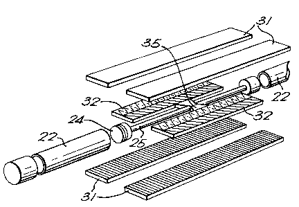
The second pump unit embodying the invention,
illustrated in Figures 2A, 2B, 2C and 2D, comprises a
double-acting pump having a cylindrical housing 21
containing two axially spaced pump cylinders 22
extending to its ends. A piston 24 is reciprocably
movable within each cylinder 22, and the two pistons
~ - _ 5 - 1333~45
are connected together by a piston rod 25 to form a piston
assembly. The pistons 24 are advantageously sealed to the
cylinder walls by sealing arrangements as described in Canadian
Application 581,748 filed 31 October, 1988 (which issued on 24
November, 1992 under patent No. 1,310,553).
The piston assembly is reciprocably driven by two
double sided linear electric motors 30, or by a motor having two
parts located in the housing 21. Each motor is generally similar
in construction to the motor 10 of Figures lA and lB, in as far
as it comprises fixed drive or induction members 31 and movable
reaction members 32 shaped as flat rectangular plates, the former
containing electric windings and the latter comprising permanent
magnets. The motors 30 however, being double sided, each
comprise two drive plates or members 31 with the associated
reaction member 32 sandwiched between them. The two motors 30
are diametrically opposed across the piston rod 25, to which the
reaction members 32 are secured by a frame 35 which extends
radially outwardly of the reaction members to mount cylindrical
guide sleeves 36 slidable along guide rails 37 extending along
the inner wall of the housing 21.
For maximum efficiency, the air gap between the
reaction members 32 and the drive members 31 has to be kept
small, and the guide means constituted by the guide sleeves 36
and the rails 37 keep the members apart in spite of any tendency
to distortion during operation.
The outer end of each cylinder 22 communicates, through
apertures in the adjacent end walls 40 of the housing 21, with
suction and discharge piping 41 by way of non-return valves
contained in a subhousing 45 detachably mounted on a support 46
secured to the end wall 40. The non-return valve arrangement is
-6- 1 3 3 3 ~ ~ j
equivalent to that shown in Figure 1 A, so that
reciprocation of the piston 24 within the cylinder 22
effects a pumping action, and the piping 41 extending
from the two supports 46 are such that the pump unit as
5 a whole operates as a double-acting pump. The suction
and discharge paths for the pumped f luid are
communicated through the join between the subhousing 45
and the support 46 by way of appropriate sealing means,
and the detachable mounting of the subhousing permits
10 the check valves it contains to be conveniently
serviced without d~sassembly of the pump unit as a
whole.
The third pump embodying the invention, shown in
Figure 3, corresponds to the pump of Figure 2 except in
15 respect of the features described below.
A hollow hexagonal support frame with walls 122 is
received within a cylindrical housing 121 for support
within it flat plate-like stator or induction members
131 of three linear electric motors 130, each also
20 comprising a flat plate-like reaction member 132, which
may again comprise a permanent magnet. Each induction
member 131 is mounted to a respective wall 122 of the
frame by means of brackets 123 so as to extend
lengthwise of the housing. The walls 122 mounting the
25 induction members 131 are spaced apart by the other
three walls which carry on inwardly extending webs 124
longitudinally extending guide beams 125.
An inner frame 135 of hollow generally triangular
cross-section mounts on each side of the flat reaction
30 members 132 so that each extends closely parallel to a
one of the induction members 131 . The frame 135 is
guided for movement axially of the housing 121 by the
guide beams 125 which are received in grooves provided
in the frame between the reaction members 132. Webs
35 136 extend inwardly from the walls of the hollow frame
13335~5
--7--
135 to a piston rod 137 connected to pistons (not
shown) functioning similarly to the pistons 24 of
Figure 2. The areas of the induction and drive members
131,132 can be large compared with the diameter of the
housing 121, so the triangular pattern of the three
motors is very efficient in respect of space and
material.
In either of the pumps of Figures 2 and 3, the
housing 21 is preferably filled with a protective
fluid, conveniently a lubricating oil, within which the
frame and the reac~ion members move. The fluid is
maintained at a pressure at least as great as the
maximum suction pressure exerted by the pump unit and
it can be communicated to other parts of, for example,
a sub-sea fluid extraction system of which the pump
unit is a part, to function as a barrier fluid.
- The motors of the pumps so far described are
preferably energised so as to operate synchronously,
and so that the piston or piston assembly is positively
driven in both directions. For high efficiency
operation, the currents in the or each drive or
induction member is phased locked to the positions of
the co-operating reaction member. This maximises the
forces applied to the piston assembly, and the pump
operates in the same way as direct current machines,
with pulling forces directly proportional to the
current. The piston assembly then has to be
accelerated from a stationary position at an end of its
stroke and then decelerated to a stationary position at
the other end of the stroke. It must then undergo the
same cycle in the other direction. The frequency of
the supply to the stator member must consequently be
changed from zero to a maximum and then back to zero,
the cycle being repeated for the return stroke but with
a shift of phase. In order to apply constant force to
-
-8- 13335~5
the piston assembly, the voltage also must be
controlled so that a constant current flows in the
winding of the drive member as the frequency varies
from zero to its maximum.
A suitable control system for achieving this motor
operation for a selected pump frequency and applied
force is schematically shown in Figure 4. Electrical
power is supplied from an alternating current source 50
to the linear motor or motors M through a variable
speed drive device 51 which may be a cyclo converter,
or an inverter with,current intermediate circuit, with
variable intermediate voltage impulse amplitude
modulation or with constant intermediate voltage and
pulse width modulation. To obtain adequately close
control, a position transducer 52 is provided to sense
the position of the reaction member, either directly or
in terms of the position of the piston assembly. The
outputs of the position transducer 52, and of a sensor
54 responsive to the current actually flowing in the
drive member or members, are applied to a control
device 55, together with signals dependent on the
selected pump frequency and pumping force from
respective input devices 56 and 57. The control device
56 provides control signals for the variable speed
device 51 so that this supplies power to the linear
motor of appropriate frequency and voltage. The
control system of Figure 4 is applicable in accordance
with the invention to the control of pump units
including linear electric motors of any configuration,
not excluding rotary pump units.
With the single acting pump configuration of
Figures 1A and 1B or the double-acting pump
configurations of Figures 2A, 2B, 2C and 2D, and Figure
3, the power input and also the pumped fluid flow are
pulsating. The pumped fluid is expelled from one
9 1333545
first half cycle, during which the flow increases from
zero to a maximum from which it is reduced again to
zero. On the next half cycle, pumped fluid is
similarly expelled from the other cylinder. In order
to reduce non-uniformity of flow, two of the pump units
of Figures 2A, 2B, 2C and 2D or of Figure 3 can be
connected together into a pump system as schematically
shown in Figure 5, and operated one quarter cycle out
of phase. Other pump units could of course be
employed.
In the position shown, with the lower piston
assembly moving to the right at maximum speed, the
upper piston assembly will shortly begin to move to
begin to discharge as the discharge from upper right
head cylinder begins to decline. Although the power
demand of the system still pulsates, considerably
smoother operation is obtained.
Figure 6 shows control arrangements for the pump
system of Figure 5 which resemble those of Figure 4 in
providing for substantially constant input and output
flow rates from the pump cylinders 22, and dynamic
control of acceleration and deceleration of the piston
assemblies between selected flow rates, and can
additionally provide for safe shutdown of the pump
system on occurrence of a supply failure or of any
other fault conditions.
The control system of Figure 6 comprises a
trajectory generator 61 receiving an input representing
a selected fluid velocity from an input device 62 and
supplying signals to a feed forward controller 64 and a
series controller 65. The pair of motors 30 of each
pump unit of the pump system receives its power supply
by way of a variable speed drive constituted by a
proportional-plus-integral controller 66 and a
converter 67. A first control loop 69 provides current
1333~4~
- 1 0 -
feedback around each proportional-plus-integral
controller 66 and the associated converter 67, the
function of this innermost loop being to control and
thereby limit current in the windings of the drive
members 31 so as to prevent damage due to excess
currents. Accurate control is ensured by the use of
the proportional-plus-integral controllers 66.
Additionally, the converters 67 are phase-locked
to the positions of the reaction members 32 by a second
inner feedback loop 70 to ensure proper synchronous
operation. To ensure this phase locking, the position
of each reaction member 32 is constantly measured as in
the system of Figure 4 and the information fed back to
the variable speed drive.
The two feed back loops so far described provide
- for efficient operation of the pump unit, and the
motors 30 are made to follow the desired velocity
profile by means of an outer position feedback loop 71
including a feedback controller 72, and by the feed
forward controller 64.
When the pump unit is running at its operating
speed, each motor pair will follow a constant
acceleration and deceleration profile, and the control
arrangements for following this trajectory operate by
controlling position rather than velocity, because it
is the piston assembly position which is the critical.
The control scheme feedback loop 71 containing a
feedback controller 72 and the series controller 65 in
the forward path to ensure good regulation. Secondly,
the feedforward controller 64 provides the necessary
control to guarantee close following of the reference
trajectory, which can be modified for example by
feedback from the current output of one of the
converters indicating excessive current demand.
The system of Figure 6 can include in addition
-"- 133354S
start-up procedures under which the peak velocity is
gradually increased until the operating value is
reached.
The system advantageously includes logic which
continually monitors pump operation and causes the pump
to decelerate to standstill on the detection of any
fault condition. Also, in the event of loss of power,
it can be arranged to effect isolation of the control
lines and "dumping" of the kinetic energy of the system
into a stator load, possibly a resistance ban, using
the inherent ability of the permanent magnets of the
reaction members 32 to generate, even though all
electrical power is lost to the drive members 31.
It will be evident that the invention can be
embodied in a variety of ways other than as
specifically illustrated and described.