Language selection

Search

Patent 1333678 Summary

Third-party information liability

Some of the information on this Web page has been provided by external sources. The Government of Canada is not responsible for the accuracy, reliability or currency of the information supplied by external sources. Users wishing to rely upon this information should consult directly with the source of the information. Content provided by external sources is not subject to official languages, privacy and accessibility requirements.

Claims and Abstract availability

Any discrepancies in the text and image of the Claims and Abstract are due to differing posting times. Text of the Claims and Abstract are posted:

  • At the time the application is open to public inspection;
  • At the time of issue of the patent (grant).
(12) Patent: (11) CA 1333678
(21) Application Number: 1333678
(54) English Title: MARINE PROPULSION DEVICE WITH THRU-TRANSOM ENGINE OIL DRAIN SYSTEM
(54) French Title: SYSTEME DE VIDANGE D'HUILE POUR PETITES EMBARCATIONS
Status: Expired and beyond the Period of Reversal
Bibliographic Data
(51) International Patent Classification (IPC):
  • B63H 21/38 (2006.01)
  • F01M 11/04 (2006.01)
(72) Inventors :
  • MEISENBURG, GARY L. (United States of America)
(73) Owners :
  • BRUNSWICK CORPORATION
(71) Applicants :
  • BRUNSWICK CORPORATION (United States of America)
(74) Agent: RICHARD J. MITCHELLMITCHELL, RICHARD J.
(74) Associate agent:
(45) Issued: 1994-12-27
(22) Filed Date: 1989-09-29
Availability of licence: N/A
Dedicated to the Public: N/A
(25) Language of filing: English

Patent Cooperation Treaty (PCT): No

(30) Application Priority Data:
Application No. Country/Territory Date
276,378 (United States of America) 1988-11-23

Abstracts

English Abstract


A fluid flow tube (9) is provided which extends from the
lower portion of the engine oil pan (7) to a point on the
boat transom (2) below the pan. The upper end portion of the
tube is connected through a control valve (10) which
communicates with the pan interior. The lower or discharge
tube end portion is connected through a fitting (11)
extending through the transom. A removable plug (17) is
associated with the fitting and, when removed, permits oil to
drain out through the transom and into an oil collection
receptacle when the control valve is open.


Claims

Note: Claims are shown in the official language in which they were submitted.

The embodiments of the invention in which an
exclusive property or privilege is claimed are defined as
follows:
1. In a marine propulsion device, the
combination comprising:
(a) a boat having a transom at its stern end,
(b) a marine internal combustion engine disposed
inboard of said boat,
(c) an oil pan mounted to said engine,
(d) and means for draining oil by gravity from
said oil pan and through said transom to the exterior of
said boat.
2. The combination of claim 1 in which said oil
draining means includes:
(a) a flexible fluid flow tube extending between
said oil pan and said transom,
(b) a control valve communicating between the
interior of said oil pan and one end portion of said tube,
(c) and pluggable oil passage means communicating
with the other end portion of said tube and extending
through said transom below the level of said oil pan to
the exterior of said boat for oil discharge therefrom.
3. The combination of claim 2:
(a) in which said oil passage means includes a
tubular fitting extending inboardly-to-outboardly through
an opening in said transom,
(b) and a plug mounted in said fitting, said plug
being removable from said fitting so that oil discharges
therethrough when said control valve is opened.
4. The combination of claim 3 in which said
control valve is mounted to said oil pan so as to
communicate with the lower portion of the oil pan interior
for removing contaminants from the latter.

Description

Note: Descriptions are shown in the official language in which they were submitted.


1 333678
This invention is directed to marine propulsion devices
which generally utilize an internal combustion engine mounted
inboard of the boat and often disposed adjacent the transom
at the boat stern. A stern drive unit is usually mounted
externally of the transom and is suitably connected through
the transom to the engine. The engine is normally mounted
above the floor of the boat and is provided with an oil pan
which depends downwardly therefrom.
Heretofore, when it has been desired to change the
engine oil, it has usually been necessary to utilize a pump
which sucks the oil out of the oil pan. This requires an
investment in additional and often expensive equipment. In
addition, it has been found that pumping the oil out through
the usual dip stick tube does not remove undesirable
contaminants which tend to collect at the bottom of the oil
pan.
The present invention eliminates the need for a pumping
system to remove the used oil from the oil pan during an oil
change, and yet provides for full removal of the oil from the
boat. An oil system which is extremely simple and
inexpensive in construction is provided.
In accordance with the various aspects of the invention
and in the present embodiment, a fluid flow tube is provided
and which extends from the lower portion of the oil pan to a
point on the transom below the pan. The upper end portion of
the tube is connected through a control valve which
communicates with the pan interior. The lower or discharge
tube end portion is connected through a fitting extending
through the transom. A removable plug is associated with the
"

1 333678
fitting and, when removed, permits oil to drain out through
the transom and into an oil collection receptacle when the
control valve is open.
The accompanying drawings illustrate the best mode
presently contemplated by the inventor for carrying out the
invention.
In the drawings:
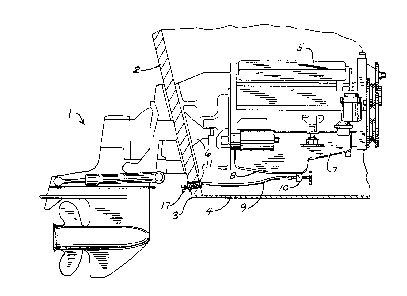
Figure 1 is a generally schematic side elevational view
of a marine propulsion device incorporating the various
lo aspects of the invention; and
Figure 2 is an enlarged fragmentary sectional view of
the through-transom fitting.
As best shown in Figure 1 of the drawings, the various
aspects of the invention are contemplated for use in
connection with a marine propulsion device which in the
present instance includes a stern drive unit 1 adapted to be
suitably mounted to the transom 2 of a boat 3 having a floor
4. An internal combustion marine engine 5 is disposed
inboard of boat 3 adjacent the stern thereof and also
adjacent transom 2. Engine 5 includes a drive output 6 which
extends through the transom to unit 1 in the usual manner.
The marine propulsion device and engine 5 include the
usual circulating oil system, and an oil pan 7 having a
bottom 8 is suitably suspended from the engine so that it
extends downwardly toward boat floor 4.
In accordance with various aspects of the invention,
--2--

1 333678
means are provided for selectively draining oil by gravity
from oil pan 7 and through transom 2 for subsequent
collection. For this purpose, and in the present embodiment,
a flexible fluid flow tube 9 is provided and which extends
from adjacent pan bottom 8 to a point on the interior of
transom 2 which is below the oil pan. A manually operable
control valve 10 is mounted to pan bottom 8 and communicates
with the lower portion of the pan interior. The upper inlet
end of tube 9 is suitably and removably connected to valve
10 10.
In addition, the lower end of tube 9 is connected for
discharging through transom 2. For this purpose, and in the
present embodiment, a tubular fitting 11 extends through an
opening 12 in the lower portion of the transom. See
especially Figure 2. Fitting 11 is suitably sealed to the
transom, as by annular sealing rings 13, and is held in place
by a nut 14 threaded to the outboard fitting end. The
inboard fitting end is barbed, as at 15, and receives the
lower end of tube 9 thereover.
Fitting 11 is provided with a flow passage 16 therein
for oil drainage therethrough. Passage 16 is selectively
pluggable adjacent its outer end by a manually removable plug
17 which is threaded into the interior of the passage.
Fitting 11 and plug 17 are preferably made of brass or
other suitable non-corrosive material.
During normal operation of the marine propulsion device,
control valve 10 is set to closed position and plug 17 closes
passage 16, thus isolating the interior of tube 9, which is
usually empty. When it is desired to drain used oil from pan

1 333678
7 during an oil changing operation, valve 10 is first opened
and then plug 17 is removed from fitting 11 as shown in
phantom in Figure 2. Oil will then be free to drain by
gravity from oil pan 7 and through tube 9 and fitting passage
16 in transom 2, and hence can dump into a bucket or the like
at the drydock. Since oil drains out from the bottom of oil
pan 7, a substantial amount of grit or other cont~min~nts
present in the pan will be carried out with the oil. When
the oil is completely drained, valve 10 is closed and plug 17
is threaded back into fitting 11.
The aspects of the invention provide a simple yet
effective system for draining oil from the inboard engine of
a marine propulsion device.
--4--

Representative Drawing
A single figure which represents the drawing illustrating the invention.
Administrative Status

2024-08-01:As part of the Next Generation Patents (NGP) transition, the Canadian Patents Database (CPD) now contains a more detailed Event History, which replicates the Event Log of our new back-office solution.

Please note that "Inactive:" events refers to events no longer in use in our new back-office solution.

For a clearer understanding of the status of the application/patent presented on this page, the site Disclaimer , as well as the definitions for Patent , Event History , Maintenance Fee  and Payment History  should be consulted.

Event History

Description Date
Inactive: Reversal of expired status 2012-12-05
Time Limit for Reversal Expired 2011-12-27
Letter Sent 2010-12-29
Inactive: IPC from MCD 2006-03-11
Grant by Issuance 1994-12-27

Abandonment History

There is no abandonment history.

Owners on Record

Note: Records showing the ownership history in alphabetical order.

Current Owners on Record
BRUNSWICK CORPORATION
Past Owners on Record
GARY L. MEISENBURG
Past Owners that do not appear in the "Owners on Record" listing will appear in other documentation within the application.
Documents

To view selected files, please enter reCAPTCHA code :


To view images, click a link in the Document Description column (Temporarily unavailable). To download the documents, select one or more checkboxes in the first column and then click the "Download Selected in PDF format (Zip Archive)" or the "Download Selected as Single PDF" button.

List of published and non-published patent-specific documents on the CPD .

If you have any difficulty accessing content, you can call the Client Service Centre at 1-866-997-1936 or send them an e-mail at CIPO Client Service Centre.

({010=All Documents, 020=As Filed, 030=As Open to Public Inspection, 040=At Issuance, 050=Examination, 060=Incoming Correspondence, 070=Miscellaneous, 080=Outgoing Correspondence, 090=Payment})


Document
Description 
Date
(yyyy-mm-dd) 
Number of pages   Size of Image (KB) 
Abstract 1995-01-12 1 18
Claims 1995-01-12 1 37
Drawings 1995-01-12 1 34
Representative Drawing 2003-03-20 1 13
Descriptions 1995-01-12 4 141
Maintenance Fee Notice 2011-02-08 1 171
Fees 1996-11-13 1 66
PCT Correspondence 1994-09-27 1 22
Prosecution correspondence 1992-04-29 2 30
Examiner Requisition 1992-01-21 1 31