Note: Descriptions are shown in the official language in which they were submitted.
1 33368~
269-3
MULTI-POSITIONABLE DOCUMENT SUPPORT STAND AND
INTERLOCKING MODULAR DOCUMENT HOLDER
BACKGROUND OF THE ~NVENTION
Field of the Invention
This invention relates to document support devices,
and more particularly relates to a desk top supported or
suspended stand for supporting documents in two or more
viewing dispositions, and document holders which can be
selectively interlocked with the support stand.
Description of the Prior Art
The term "document" hereinafter refers to a single
page or a multiple number of pages.
The term "document holder" hereinafter refers to
that type of device which is adapted to æecure a
document, such as in the form of a book, spiral bound
manual, loose-leaf binder or the like, as well as
conventional document stands, such as will be described,
which are modified in accordance with the principles of
2~ this invention.
Document support stands for supporting a document or
document holder are well-known in the art and come in a
variety of configurations and structures. Many
conventional stands are designed to rest on a desk or
table top, and to ..................
Xi.. .
1 333682
-
support the document at a substantial viewing angle to the
1 horizontal.
One of the primary disadvantages of many conventional
viewing stands is that they are not adaptable for supporting
a document in multiple viewing positions without
manipulating the document on the stand.
For example, one conventional type of document
support stand is L-shaped and includes an easel back with a
bottom support ledge on which the document or document
holder rests. This easel type stand is designed-primarily
to support a book, æpiral bound manual, loose-leaf binder or
other form of document holder with its spine in a vertical
disposition, the edge of the spine being supported by the
ledge of the stand. The stand is not designed to support
the document holder on the side edge of the holder's back
cover with its spine horizontal, nor is the document holder
designed to be supported in such a manner, as the document
holder supported thusly oftentimes folds uncontrollably at
creases formed in its cover, collapses under its weight or
generally cannot be maintained upright and open on the
stand. As a matter of course, such documents holders, and
other types as well, are often simply placed horizontally
on the desk top surface causing the operator to have to
refocus in different planes and distances when referring
back and forth between document and typewriter or video
display terminal.
Certain other types of conventional viewing stands
include a document securing bar, page retainer or sentence
marker which extends across the viewing surface of the
stand. Many times the securing bar is suitable to hold a
manual or loose-leaf binder against its viewing surface with
the spine of the manual or binder in a horizontal
disposition, especially if the manual or binder is
lightweight and not bulky.
-2-
1 333682
However, changing the reading pattern requires
1 removing the securing bar and manipulating the manual on the
stand, and then readjusting the securing bar to support the
manual in its new disposition. Furthermore, the securing
bar itself may interfere with the material being read, and
it may be nececcary to constantly readjust the position of
the securing bar.
Another type of conventional stand is the clipboard
type, having a support back and a clip fastener mounted on
the support back. Like other conventional document support
stands, manipulation of the document on the stand is
required to change the reading pattern. Furthermore, this
type of stand is impractical in use because it requires
refastening the document each time a page is turned. Also,
the clip fastener may be undersized to support a bulky
manual.
The problem of having to change the reading pattern
is exacerbated in today's society where many of the manuals
digested are of a technical nature and include diagrams and
charts in columnar form. This is particularly true with
present day computer software documentation and training
~ manuals in which text is presented in a standard book
format, with pages reading from left to right and computer
screen illustrations, flow charts, programs and tables being
presented from top to bottom. The reader must constantly
adjust his reading pattern by manipulating the manual. This
constant need for reorientation by the computer operator
trainee is inefficient, confusing and tiring, all of which
impairs the learning process.
The further problem with document support stands
which are currently available is that they are not adapted
to adequately support the newer forms of loose-leaf binders.
These binders are often of the type which use a loose-leaf D
ring mechanism, with the mechanism being offset from the
center spine panel of the cover or jacket and being mounted
-3-
- 1 333682
on the inside back cover of the binder. Offsetting the ring
1 mechanism is advantageous for storing pages uniformly and
compactly. However, such offsetting requires the cover or
jacket of the binder be made considerably larger than a
conventional binder cover. The large cover consumes
valuable desk top space, and the binders are cumbersome and
poorly supported on the side edges of their cover by
conventional viewing stands.
No currently available viewing stand has the ability
to rotatably support a binder mech~nism of a loose-leaf
binder, which mechanism may be removed from the cover or
jacket of the loose-leaf binder and directly secured to the
viewing stand, without the jacket.
Furthermore, the viewing stands which are currently
available have their own supporting mechanism, such as a
bracket mounted on the back of the viewing stand to support
the stand in a particular angular disposition for viewing
documents. No common support mechanism is currently
available which is adapted to interfit with and support
various types of document support stands so that different
stands may be interchanged on the same supporting mechanism.
Consequently, many documents are not properly supported for
viewing because of the absence of a common document support
mech~nicm.
OBJECTS AND SUMMARY OF THE lNv~NllON
It is an object of the present invention to provide a
document support stand adapted for securing a document
holder in multiple viewing positions.
It is another object of the present invention to
provide a desk top or suspended multi-positionable document
support stand.
It is yet another object of the present invention to
provide a support stand and a document holder adapted to be
selectively interlocked on the support stand and supported
-4-
-- 1 333682
by the stand in multiple positions.
1 It is a further object of the present invention to
provide a support stand and document holder, where the
holder includes a mechanism for securing documents, which
mechanism may be removed and secured to the support stand.
It is a still further object of the present invention
to provide a support stand which is simple in construction
and easily manufactured.
It is yet a further object of the present invention
to provide a document support stand which secures the
document holder to the stand without interfering with the
text of the document.
It is still another object of the present invention
to provide a document support stand and document holder,
each having cooperating interlocking mechanisms for
removably mounting the document holder on the support
stand.
It is a further object of the present invention to
provide a document support stand which overcomes the
inherent disadvantages of known support stands.
It is a still further object of the present invention
to provide a system of interchangeable document holders and
document support devices, each of which includes cooperating
interlocking means which allow the free interchange of one
holder or support device for another.
It is another object of the present invention to
provide a document support stand which will improve the
ergonomic environment of individuals referring to visual
information.
It is a further object of the present invention to
provide a document support stand that will increase the
comfort, understanding and productivity of video display
terminal operators.
-5-
,~ 1 333682
r ~ ~
It is yet another object of the present invention to
1 provide a document support stand that will properly support
for viewing and interpretation information presented in
such visual formats as: instructional and reference manuals,
word processing, application, integrated or computer
assisted design (CAD) programs, graphs, spreadsheets and the
like.
In accordance with one aspect of the present
invention, the document support stand includes a main body
which may be formed in the shape of a truncated pyramid.
The body has a viewing side (which is defined by the base
side of the truncated pyramid body), and first and second
support sides for supporting the stand on a desk or table
top, or other support surface. The support sides are
transversely disposed to each other and preferably
constitute adjacent sides on the truncated pyramid body.
Thus, the body may be rotated 90- with either its first or
second support side resting on the desk or table top, so
that the viewing side may be disposed in different
positions.
The main body of the stand includes a mounting device
for removably mounting a document holder on the body. The
mounting device is secured to the viewing side of the main
body.
In a preferred form of the invention, the mounting
device is an elongated bracket, C-shaped in cross-section,
which defines a T-slot having an exposed open end. The
bracket is mounted in a recess formed across the surface of
the main body's viewing side.
The document support stand may be hollow, and
include on its inside a movable weight, such as in the form
of a bean bag or the like, which allows the center of
gravity of the document support stand to change when the
stand is repositioned from one support side to another.
-6-
1 333682
r ' ~ ~
According to the present invention, a document
1 holder, such as a loose-leaf binder, includes a document
mounting device (for example, the binder mechanism), a
support for the document mounting device (for example, the
jacket, including the front and back covers, on which the
binder mec~nism is mou~lL~d), and an elongated-member for
mounting the document holder on the support stand.
The elongated member in its preferred form is T-
shaped in cross-section and, in the example above of a
loose-leaf binder-type document holder, is mounted on the
spine of the binder's jacket. The T-shaped member of the
holder is slidably received by the C-bracket of the stand
through the C-bracket's exposed open end, so that the
document holder may be secured to the viewing side of the
stand's main body.
Positioned thusly on the stand, the document holder
and its documents may be disposed in different positions,
for viewing the documents from left to right or top to
bottom, by simply rotating the stand 90 so that the stand
rests on either of its support sides.
A latching mechanism in the form of a cooperating
wedge protrusion and conforming recess mounted on the
elongated T-shaped member of the document holder and formed
in the C-bracket of the stand, respectively, or vice versa,
may be included to ensure that the document holder remains
secured to the stand until intentionally removed.
These and other objects, features and advantages of
this invention will be apparent from the following detailed
description of illustrative embodiments thereof, which is to
be read in connection with the accompanying drawings.
3o
BRIEF DESCRIPTION OF THE DRAWINGS
Fig. 1 is a front perspective view of a document
support stand and a document holder, constructed in
accordance with one form of the present invention.
-7-
1 333682
Fig. 2 is a rear perspective view of the document
support stand and document holder shown in Fig. 1, with
the document support stand partially broken away at
portions thereof.
Fig. 3 (shown on sheet 1 of the drawings) is a
fragmentary top view of the document support stand shown
in Fig. 1, with the document holder mounted thereon.
Fig. 3A is a fragmentary sectional view of the
document support stand shown in Fig.l, illustrating one
form of the ~iewing side thereof.
Fig. 3B is a fragmentary sectional view of the
document support stand shown in Fig.l, illustrating
another form of the viewing side thereof.
Fig. 4 (shown on sheet 2 of the drawings) is a
perspective view of a document support stand, constructed
in accordance with a second form of the present
invention.
Fig. 4A (shown on sheet 2 of the drawings) is a
front perspective view, partially broken away, of a
document support stand, constructed in accordance with a
modification to the form of the invention shown in Fig.4.
Fig. 5 is a front elevational view, partially broken
away, of a document support stand, constructed in
accordance with a third form of the present invention.
Fig. 6 is a perspective view, partially broken away,
of a document support stand, constructed in accordance
with a fourth form of the present invention.
Fig. 7 is a fragmentary side view of the document
support stand shown in Fig. 6, with the main ~ody of the
stand rotated 90 from the viewing position shown in
Fig. 6.
Fig. 8 is a front perspective view of a document
support stand, constructed in accordance with a fifth
form of the present invention.
Fig. 9 is a perspective view of the document support
stand shown in Fig. 8, with a pair of loose-leaf binders
mounted in different dispositions on the stand.
-- 8
~ .-
. ~-,
1 333682
-~ Fig. 10 (shown on sheet 4 of the drawings) i8 a
fragmentary perspective view of a loo~e-leaf binder-type
document holder, as an alternative to the form
illustrated by Figs. 2 and 3.
Fig. 11 is a perspective view, partially broken
away, of a document holder, constructed in accordance
with a third form of the present invention.
Fig. 12 is a perspective view of a document holder,
constructed in accordance with a fourth form of the
present invention.
Fig. 13 is a perspective view, partially broken
away, of a document holder, const~ucted in accordance
with a fifth form of the present invention.
Fig. 14 (shown on sheet 4 of the drawings) is a
perspective view of an adapter plate, constructed in
accordance with the present invention, and a loose-leaf
binder, illustrating its attachment to the adapter plate.
Fig. 15 is a perspective view of a document support
stand, partially broken away, formed in accordance with
another embodiment.
Fig. 16 is a perspective view of the document
support stand shown in Fig. 4A, partially bro~en away,
modified in accordance with another embodiment of the
present invention.
Fig. 17 is a perspective view of the stand shown in
Fig. 16, shown in a different rest position.
Fig. 18 i8 a longitudinal cross-sectional view of
the document holder and document support stand, modified
to include a latching mechanism.
Fig. 19 is a longitudinal cross-sectional view of
portions of the document holder and stand, illustrating
another form of a latching mechanism.
Fig. 20 is a cross-sectional view of an alternative
form of the binder-type document holder shown in Fig. 10.
3S Fig. 21 is a side elevational view of the T-rail and
binder mechanism of the document holder shown in Fig. 20.
X ~
-- 1 333682
Fig. 22 is a rear perspective view of a document
1 holder and a document support stand, similar to that shown
in Fig. 2, modified in accordance with another form of the
present invention.
Fig. 23 is a transverse cross-sectional view of a
loose-leaf binder-type document holder, shown without the
jacket, formed in accordance with another form of the
invention.
Fig. 24 is a transverse cross-sectional view of
another document holder formed in accordance with another
form of the present invention.
Fig. 25 is a front elevational view of a second form
of an adapter plate, constructed in accordance with the
present invention.
Fig. 26 is a front elevational view of a third form
f an adapter plate constructed in accordance with the
present invention.
Fig. 27 is a front elevational view of a fourth form
of an adapter plate, constructed in accordance with the
present invention.
Fig. 28 is a front elevational view of a document
support stand similar in many respects to that shown in
Figs. 8 and 9 but adapted to receive a locking mechanism.
Fig. 29 is a top elevational view of a locking
mechanism for use with the document support stand shown in
Fig. 28.
Fig. 30 is a front elevational view of the document
support stand shown in Fig. 28, with the locking mechanism
shown in Fig. 29 attached to it.
Fig. 31 is a cross-sectional view of the document
support stand and locking mechanism shown in Fig. 30, taken
along line 31-31 of Fig. 30.
Fig. 32 is a cross-sectional view of an alternative
form of locking mechanism which may be used with the
document support stand illustrated by Fig. 28.
-10-
1 33~682
Fig. 33 is a perspective view of a spacer member
1 adapted for use with the document support stand shown in
Fig. 28.
Fig. 34 is a longit~in~l cross-sectional view of
another form of a locking device for use with the stand of
Fig. 28, the device being shown in an unlocked state.
Fig. 35 is a longitll~in~l cross-sectional view of
the device shown in Fig. 34 in a locked state.
Fig. 36 is a perspective view of a rotatable stand
constructed in accordance with another embodiment.
Fig. 37 is an exploded side elevational view of the
stand shown in Fig. 36.
Fig. 38 is a~side elevational view of a pin block
used in conjunction with the rotatable stand shown in Fig.
36.
Fig. 39 is a perspective view of a pair of sleeves
used for securing a document holder to a document support
stand, and formed in accordance with the present invention.
Fig. 40 is a perspective view of the sleeves shown
in Fig. 39, shown securing a document holder to a support
stand.
Fig. 41 is a perspective view of an alternative form
of document holder, constructed in accordance with the
present invention.
Fig. 42 is a perspective view of another form of a
document holder, constructed in accordance with the present
invention.
Fig. 43 is a perspective view of another document
holder, formed in accordance with the present invention.
Fig. 44 is a perspective view of an alternative form
3o of an adapter constructed in accordance with the present
invention.
Fig. 45 is a perspective view of a document holder
and stand, formed in accordance with the present invention
and modified to include a locking mechanism.
--11--
-
1 333682
Fig. 46 is a top perspective view of a document
1 support stand having a number of document holders mounted
thereon, which stand is formed in accordance with the
present invention.
Fig. 47 is a bottom perspective view of a document
holder formed in accordance with the present invention.
Fig. 48 is a bottom perspective view of a document
holder formed in accordance with the present invention.
DETAILED DESCRIPTION OF THE PREFERRED EMBODIMENTS
Initially referring to Figs. 1 and 2, it will be seen
that a document support stand 2, constructed in accordance
with one form of the present invention, includes a main body
4 formed in the shape of a truncated pyramid. The body 4
may be of solid construction, for enhanced stability, or
15 formed from a series of joined or integral sides to provide
the overall configuration of the truncated pyramid.
In this form of the invention, the main body 4
includes a viewing side 6 (defined by the base of the
truncated pyramid construction), and four support sides 8a,
20 8b, 8c, 8d (defined by the truncated pyramid's mutually
converging sides). The viewing side 6 is planar in nature,
to provide a flat surface for holding and viewing a document f
mounted thereon, as will be explained. The four support `
sides 8a-d are also planar, to provide a stable, flat
25 surface on which the stand may rest when positioned on a
desk or table top or other horizontal support surface.
In the embodiment illustrated by Figs. 1 and 2, only
two sides 8a, 8b are of importance in supporting the stand,
although four sides provide greater versatility in
30 positioning the stand on the desk or table top. The two
sides 8a, 8b which are used for support are transversely
disposed to each other (each being joined to one of
transversely disposed first and second edges 10, 12 of the
viewing side), and define adjacent sides of the truncated
-12-
-- 1 333682
.. . ~ (
pyramid body. Referred to hereinafter as the first and
1 second support sides 8a, 8b, they extend angularly from the
viewing side 6 on the same side of the plane in which the
viewing side resides.
The viewing side 6 is disposed at a substantial angle
to the horizontal in order to minimize eye strain and light
reflection. Preferably, the angle A defined by the first
support side 8a and the viewing side 6 (at the first edge
10), and the angle B defined by the second support side 8b
and the viewing side 6 (at the second edge 12), are each
about 40- to provide the desired angle of viewing. If each
angle is selected to be the same, then the 40 slope of the
viewing side 6 with respect to the desk or table top will be
maintained in all dispositions of the stand, that is, when
the stand is resting on any support side 8a, 8b. However,
it may be desirable to form the stand with different angles
A and B, for example, 40 and 50 respectively, so that the
user may select his preferred viewing angle by merely
rotating the stand to rest on a corresponding support side
8a, 8b.
Sides 8c and 8d are similarly joined to edges of the
viewing side 6, with side 8c opposite side 8a and side 8d
opposite side 8b, and similarly define angles C and D
respectively with the viewing side. It may be desirable to
form the body 4 with different angles A and C, for example
and 50 respectively, or with different angles B and D,
so that the reader may rotate the stand 180 for different
viewing angles.
The viewing side 6 is preferably rectangular in
shape, and of sufficient dimensions to adequately support a
loose-leaf binder or other document holder. The size of the
stand, and its viewing side, is selected to fit the needs of
the user and the document holders envisioned to be
supported.
-13-
-- 1 333682
,. ~ (
The document support stand 2 further includes a
provision for mounting a document holder 14 on the main body
4. In one form of the invention, an elongated bracket 16
having a C-shape in cross-section is mounted in a recess 17
formed in the surface of the viewing side 6 of the body 4.
5 As shown in Fig. 3, the bracket 16 includes a back plate 18,
a pair of side plates 20 joined to the back plate 18 on the
back plate's opposite transverse edges and extending
perpendicularly from the back plate on the same side of the
back plate, and a pair of inwardly facing arms 22, each arm
10 22 being joined to a respective side plate 20 and being
spaced apart from the back plate 18.
The C-bracket 16 defines an elongated, T-shaped slot
24, having narrowed and widened portions 26, 28. The
narrowed portion 26 of the T-slot 24 is defined between the
15 pair of arms 22, while the widened portion 28 of the T-slot
24 is defined between the back plate 18 and each arm 22.
The bracket 16 is mounted on the main body 4 of the
stand 2 with its back plate 18 abutting against the recessed
surface of the viewing side 6. Fasteners, glue or other
20 means may be employed to mount the bracket 16 in the recess
17.
The C-bracket 16 mounted in the recessed surface of
the viewing side 6 may extend entirely across the viewing
side, or may extend from one edge of the viewing side (shown
25 in Fig. 1 as the top edge 30) and terminate before reaching
the opposite edge (for example, the bottom edge 32). The
terminated edge 34 of the bracket 16 defined by the end of
the recess 17 provides a stop, which limits the extent to
which a document holder 14 may be received by the bracket
30 16. This prevents the document holder 14 from inadvertently
slipping out of the bracket slot 24 when mounted on the
stand 2, and also lets the user know that the holder is
fully and properly mounted on the stand.
--14--
1 3~3~2
As mentioned above, at least one end 36 of the
1 bracket 16 extends to an edge of the viewing side 6. Thus,
this end 36 is exposed, and is open to the slot 24 so that a
document holder 14 may be slidably received by the slot
through the exposed open end 36.
Thus, the stand may be described as being rotatable
about a z-axis of rotation running through the body 4, with
the viewing side 6 residing in an x-y coordinate plane that
is perpendicular to the z-axis of rotation so that the
viewing side of the stand correspondingly turns within the
x-y coordinate plane and is adjustable in position within
the x-y coordinate plane.
In another form of the invention, as illustrated by
Fig. 15, the document support stand 2 may be hollow, with
its sides completely enclosing its interior. An unattached,
weighted means 200 is inserted into the hollow interior of
the stand and confined within the interior by the stand's
sides. The weighted means 200 is movable and will fall to
whichever support side the stand is resting on whenever the
document stand 2 is repositioned.
This particular embodiment is advantageous in that it
allows the center of gravity of the document stand to change
to the optimum position for preventing the stand from
toppling over under the weight of the document which it
supports.
Also, the document support stand 2 of Fig. 15 may be
manufactured from a plastic or other lightweight material so
that most of its weight can be attributed to the movable
weight 200. Thus, the document support stand 2 will always
maintain a low center of gravity no matter what support side
it rests on, further adding to the stability of the stand.
Furthermore, having a movable weight 200 provides for
economy of manufacture because the stand may be formed
without any real concern for the weight distribution of its
parts and how they relate to function.
-15-
1 333682
-
The weighted means 200 used in the document support
1 stand 2 of Fig. 15 may be one of a variety of different
materials or objects, including small bags of peas, beans or
gravel, loose sand or liquid. The weighted means 200 may be
introduced into the interior of the support stand through an
access opening 202 formed in one of the sides of the stand
(preferably the unused top side 204). The opening 202 may
be threaded to receive and secure to the stand a threaded
cap 206 which is flush with the outer surface of the top
side 204 and, if water is used as the weighted means 200,
may be formed to define a watertight closure for the stand.
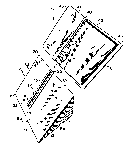
Fig. 3, in association with Figs. 1 and 2,
illustrates one form of a document holder 14 constructed in
accordance with the invention, and demonstrates how that
document holder is mounted on the document support stand 2.
A conventional loose-leaf binder 38, having a binder
mech~nism 40 to hold pages or documents 42, and a jacket 44
having a front and back cover 46, 48, with the binder
mechanism 40 mounted on the inside surface of the jacket at
its spine 50, is modified to further include an elongated
rail 52 mounted on the outside surface of the jacket 44 at
or near the spine 50. The elongated rail 52 has a T-shape
in cross-section with narrowed and widened portions 54, 56
that correspond in dimensions to the widened and narrowed
portions 28, 26 of the slot 24 defined by the C-bracket 16.
The T-rail 52 may include a back plate 58 mounted on the
narrowed portion 54 and spaced from its widened portion 56
for mounting the rail on the loose-leaf binder jacket, such
as by gluing, fasteners or other means. Or, the T-rail 52
may be integrally formed with the jacket when the loose-leaf
binder is made.
As shown in Figs. 1 through 3, the loose-leaf binder-
type document holder 14 is removably mounted on the document
support stand 2 by sliding its T-rail 52 through the exposed
end 36 of the C-bracket 16 into the bracket's T-slot 24
-16-
1 333682
.. ~ (
until the document holder is centered on the viewing side 6
l or abuts the terminated end 34 of the C-bracket.
The C-bracket 16 of the stand 2 securely holds the
document holder 14 and supports it at its spine S0. Most
loose-leaf binders are adapted to fold about the binder
mechanism and the documents held thereby to protect the
documents, and are made to flex at fold lines or creases 60
running parallel to the spine 50. The loose-leaf jacket 44
provides poor support when stood on its side edges 61,
because it has a tendency to flex at its fold lines. The
best support for the loose-leaf binder is thus provided by
positioning the T-rail 52 at the spine 50 of the loose-leaf
jacket, where the most weight of the loose-leaf binder and
where the fold lines 60 are situated.
Thus, the loose-leaf binder 38 may be repositioned by
the reader to different viewing dispositions, for instance,
for changing a reading pattern of from left to right to top
to bottom, without manipulating the document holder on the
stand 2, simply by rotating the stand so so that it rests
on a different support side 8a, 8b.
Figs. 1 through 3 show the C-bracket 16 protruding
slightly above the surface of the viewing side 6. It may be
desirable to mount the C-bracket 16 flush to the surface of
the viewing side 6, as illustrated by Fig. 3A, or slightly
deeper in the viewing side 6 to compensate for the thickness
f the T-rail s back plate 58, so that the jacket 44
substantially rests on the surface of the viewing side 6 for
flat support over more of the loose-leaf jacket's area.
However, it is envisioned to be within the scope of this
invention, and may also be desirable, to mount the C-bracket
16 directly on the surface of the viewing side, without
forming a recess 17 in the viewing side 6, so that a
slightly backward bend to the loose-leaf cover is provided
which tends to further maintain the loose-leaf binder 38 in
an open condition when disposed with its spine 50
-17-
- 1 333682
horizontal.
1 Of course, it is also envisioned to be within the
scope of this invention to eliminate a separate C-bracket
member 16 and to form the T-slot 24 directly in the surface
of the viewing side 6, as illustrated by Fig. 3B. In such a
case, the narrowed and widened portions 26, 28 of the T-slot
24 are defined by first and second portions 64, 66 of the
viewing side, the first and second portions 64, 66 being L-
shaped and in relative mirror image disposition, as
illustrated.
It is further envisioned to reverse the positions of
the T-rail 52 and the C-bracket 16 or T-slot 24. For
example, as illustrated by Fig. 22, the C-bracket 16 may be
mounted on the document holder 14, and the T-rail 52 may be
mounted on the support stand 2 with comparable results.
Fig. 4 illustrates a second form of a document
support stand, constructed in accordance with the present
invention. This alternative form of the stand includes a
main body 70 formed as a one-piece, plate-like member bent
into three non-parallel, planar dispositions to define three
integral sides. One side 72 is the viewing side of the
stand; the other two sides are first and second support
sides 74, 76. Each of the viewing and support sides 72-76
perform a similar function to that performed by the sides of
the stand shown in Figs. 1 through 3, and define similar
angles A and B therebetween, as in the first embodiment
described.
An elongated slot 78 is formed directly in the
viewing side 72 of the plate-like body 70, and extends from
the top edge 80 of the stand and across the viewing side 72,
and terminates short of the fold 82, as illustrated by Fig.
4. The thickness of the plate surrounding the slot 78 is
substantially equal to the space defined between the back
plate 58 and the widened portions 56 of the T-rail 52 of the
document holder, as shown in Fig. 3, and the width of the
-18-
_ 1 333~68
. ~ (
slot 78 conforms to the width of the narrowed portion 54 of
l the T-rail. Thus, the document holder is slidably mountable
on the document support stand, with its T-rail 52 being
securely captured within the slot 78 formed in the viewing
side of the stand.
It is evident from the above description that the
second support side 76 may be eliminated, as illustrated by
Fig. 4a, with the possible sacrifice of some stability to
the stand. The modified stand would then be comprised of
the viewing side 72 and the first support side 74. The side
edges 84, 86 of the viewing side 72 and the first support
side 74 constitute the support for the stand when it is
rotated 90- from the position shown in Figs. 4 and 4a, so
that the stand rests on these edges 84, 86.
As in the other embodiments, the first and second
support sides 74, 76 of the stand of Fig. 4 define a 40-
angle with the viewing side 72 so that the viewing side is
disposed at a substantial angle to the desk or table top to
lessen eye strain and fatigue. In the modified stand of
Fig. 4a, the side edge 86 of the first support side 74
resides in a plane which defines a 40- angle with the
viewing side 72.
To increase stability of the edge supported stand
shown in Fig. 4a, a weight 88 may be added. The weight 88
is mounted on the first support side 74 near its side edge
86. The weight 88 lowers the center of gravity of the stand
when it is disposed on its side edge, and minimizes the
chance of the stand toppling under the weight of the
document holder.
Alternatively, the stand of Fig. 4A may be made of
hollow sides 72, 74, as shown in Fig. 16, to receive and
retain a moveable ballast 208 or weight, such as water or
loose sand. The hollow interiors of each side 72, 74 may be
in communication to allow the moveable ballast 208 to flow
from one side to the other. The loose ballast 208 partially
-19-
1 3~3682
,. ,. ~ ~
fills the interior of each side and thus occupies the lower
1 interior portion of each side. When the stand is
repositioned, as shown in Fig. 17, the water or sand will
shift accordingly and will help hold the stand upright in
the new position. The same feature of hollow sides
containing a loose and moveable ballast may be incorporated
in the stand shown in Fig. 4, described previously, and that
shown in Fig. 6, which is to be described.
Fig. 5 shows a third form of the document support
stand, and combines the features of the stands shown in
Figs. 1 through 3 and Figs. 4 and 4A. The stand includes a
body 90 having an overall pyramid or truncated pyramid
geometric shape, as with the first stand described (Figs. 1-
3), but which is only three sided and edge supported in one
of its dispositions, as well as being formed from a bent
plate-like member, as in the second embodiment of the stand
and its modification (Figs. 4 and 4A).
The main body 90 of the stand includes a rectangular,
planar viewing side 92 (the base of the pyramid
configuration), and two planar support sides 94, 96 joined
to the opposite edges of the viewing side. Each support
side 94, 96 defines with the viewing side 92 an acute angle,
preferably about 40-, along the opposite edges 98 of the
viewing side. The support sides 94, 96 extend from the
viewing side 92 on the same side of the plane in which the
viewing side resides, and mutually converge towards the rear
of the stand to join each other and define a back edge 100.
Each support side 94, 96 is trapezoidal in shape, and
includes exposed side edges 102. These side edges 102 are
used to support the stand on a desk or table top, as
exemplified by the disposition of the stand shown in Fig. 5.
The side edges 102 of the support sides 94, 96 preferably
reside in planes which define angles of 40- with the viewing
side 92, so that the viewing side 92 is disposed at the same
angle with respect to the desk or table top with the stand
-20-
1 33~6~
in any user selectable disposition. Alternatively, as in
1 the embodiment shown in Figs. 1 through 3, the angles of the
support sides 94, 96 and side edges 102, with respect to the
viewing side 92, may be selected to provide different
viewing angles for different dispositions of the stand.
As in the stand shown in Figs. 4 and 4A, the stand of
Fig. 5 has an elongated slot 104 formed in its viewing side
92, with an open end 106 of the slot disposed at the viewing
side's top edge 108. The elongated slot 104 is dimensioned
to receive the T-rail 52 of a document holder, such as that
of the holder described previously and shown in Fig. 3.
The stand of Fig. 5 can be rotated to rest on either
of the support sides 94, 96, or on the exposed edges 102 of
the support sides, so that the slot 104 will be either
vertically or horizontally disposed. A document holder thus
received by the slot and secured to the viewing side 92 of
the stand is displayable in different dispositions, to
change reading patterns, for instance, for left to right or
top to bottom viewing, without manipulating the document
holder on the stand, by merely rotating the stand so that it
rests on its support sides 94, 96 or the side edges 102 of
the support sides.
Referring now to Figs. 6 and 7, a fourth form of a
document support stand, constructed in accordance with the
present invention, is shown. In this form of the invention,
a document holder may be suspended above the workplace and
may be adjusted both in viewing angle and in its rotation.
The document support stand first includes a
conventional, double-arm multi-function support bracket 110.
Such brackets are typically used for supporting a swing arm
3o type lamp over a desk top, drafting table or the like, and
are usually mounted at the edge of the desk or table. Such
a support bracket is used on the swing-arm lamp Model No.
173-7500, manufactured by Electrix, Inc.
-21-
1 333682
The support bracket 110 includes a pinion 112 which
1 is rotatably held by a sleeve 114. A knob 116 can adjust
the pressure that the sleeve 114 exerts on the pinion 112
and the degree to which the pinion is rotatable.
The sleeve 114 is clamped between two side brackets
118, so that the sleeve, and the pinion 112 held by the
sleeve, are angularly adjustable from the vertical. The
angular disposition of the pinion 112 selected by the user
may be maintained by tightening the knob 116, which
increases the side brackets' holding force on the sleeve
114.
The pinion 112 includes a flange 120 mounted on its
free end. Holes 122 are formed on the flange 120 for
receiving screws or other fasteners for mounting a lamp or
other object to the support bracket.
In the present invention, a planar plate-like member
124, rectangular in form, is mounted on the flange 120 of
the support bracket 110. The plate-like member 124 includes
a front side 126, constituting the viewing side of the
document support stand, and an opposite rear side 128, to
which the flange 120 of the support bracket is attached.
As in the other previously described embodiments, the
document support stand of Figs. 6 and 7 includes a provision
for mounting a document holder to the stand. The same forms
of the document holder mounting structure used in the other
stands of-the invention may be employed here. For example,
the C-bracket 16 shown in Fig. 3 may be mounted on the
surface of the viewing side 126 of the plate-like member
124, or mounted flush to the surface in a recess formed in
the viewing side 126. Alternatively, as exemplified by Fig.
3B, a T-slot 24 may be formed directly in the member and
defined by L-shaped member portions 64, 66.
As a further alternative, the member 124 may be a
relatively thin plate formed with an elongated slot, as
employed in the stands of Figs. 4 and 4A, with the mounting
-22-
1 333682
flange 120 of the support bracket 110 being positioned on
1 the rear side of the member so as not to interfere with the
slot.
DepPn~ing on the means employed to define the slot 24
in the member, the slot may be open at an edge 80 of the
member so that the corresponding T-rail 52 of a document
holder, such as that previously described and shown in Fig.
3, may be slidingly received by the slot 24 and secured to
the viewing side 126 of the stand.
The document support stand of Figs. 6 and 7 provides
different angles of viewing for the reader by loosening the
knob 116 and adjusting the member 124 up or down, as
- illustrated by arrows A in Figure 7. A document holder
secured in the slot 24 on the viewing side 126 of the stand
may be rotated to different viewing dispositions (by the
pinion 112 turning in the sleeve 114, as indicated by arrow
B), for example, the different positions shown in Figs. 6
and 7, so that the reader may quickly and efficiently adjust
his reading pattern, without manipulating the document
holder on the stand.
Thus, like the stand of Fig. 1, the stand shown in
Fig. 6 may be described as being rotatable about a z-axis of
rotation running through the plate-like member 124, with the
front or viewing side 126 residing in an x-y coordinate
plane that is perpendicular to the z-axis of rotation so
that the viewing side of the stand correspondingly turns
within the x-y coordinate plane and is adjusted in position
within the x-y coordinate plane.
Another form of a document support stand is shown in
Figs. 8 and 9. This form of the invention has the
capability of securely but removably holding one or more
document holders 14 in multiple viewing dispositions on the
stand.
-23-
- 1 333682
The document support stand includes a main body 130
1 which may be formed as an upstanding wedge-shaped block
(i.e., triangular in section). The body 130 has a flat
support side 132 which is provided for resting the stand on
a desk or table top. It also includes a viewing side 134,
disposed at a substantial angle to the desk or table top.
The support side 132 and viewing side 134 are joined at a
common edge 136, and define between them an acute angle of
preferably about 40-.
Other forms of the main body 130 may be employed,
rather than the triangular shape shown in Figs. 8 and 9.
For example, a plate-like member (such as that shown in
Figs. 6 and 7), having its front side constituting the
viewing side of the stand, and including a support bracket
extending angularly from its rear side to the desk top, may
be suitably used. Other forms of the main body are
envisioned and may be employed, as long as each presents a
viewing side for mounting various document holders.
The surface of the viewing side 134 is formed with at
least one horizontally disposed T-slot 138, and with at
least one vertically disposed T-slot 140, although Fig. 8
shows two vertical slots 140 as the preferred number. The
vertical slots 140 extend from the top edge 142 of the
stand's viewing side and terminate short of the bottom edge
136. In the preferred form of the stand shown in Fig. 8,
the horizontal slot 138 is interposed between the two
vertical slots 140 and extends slightly beyond each. The
horizontal slot 138 terminates short of two side edges 144
of the viewing side 134, although it may extend to the side
edges, in the same fashion as the vertical slots 140 extend
to the top edge 142.
The T-slots 138, 140 formed in the surface of the
viewing side 134 are substantially the same as the slot 24
defined by the C-bracket 16 shown in Fig. 3, or defined by
the viewing sides of the other stands, as shown in Figs. 3A
-24-
1 33~682
,. ,. ~ ~
and 3B. That is, the slots 138, 140 are formed with
1 narrowed portions 146 at the surface of the viewing side
134, and widened portions 148 more recessed from the
surface, so that each slot is adapted to receive the
complementary shaped T-rail of the document holders.
If both the horizontal and vertical T-slots 138, 140
are formed to extend to the edges of the viewing side 134,
their ends are open and exposed so that the document
holder's rail may be slid into the open end of the slots.
However, it may be desirable to seat the document
holder's rail in either slot 138, 140 by approaching the
slot in a direction normal to the viewing side 134 (as
opposed to sliding the holder in the slot's exposed end).
As shown in Fig. 8, this preferred form of the stand
includes portions of the viewing surface which define an
enlargement 150 in each slot, which enlargement 150 extends
only partially over the length of its respective slot.
The width of the enlargement 150 is equal to or
greater than that of the widened portion 56 of the T-rail 52
on the document holder. This enlargement may be in the form
of a concave depression defined by inwardly sloping,
recessed portions 152 of the viewing side's surface disposed
on opposite sides of the slot, which converge into the
widened portion 148 of the slot. The concave depression
formed in the viewing side is perfectly adapted for
receiving a loose-leaf binder with a convex spine.
The document holder 14 may be positioned at the
enlargement with its T-rail 52 received by the widened
portion 148 of the slot. The holder 14 is then shifted
axially along the slot away from the enlargement 150, where
its T-rail 52 is held captive by the narrower portion 146 of
the slot. The document holder is properly seated on the
stand when its T-rail engages the terminated end 154 of the
slot.
-25-
1 333682
As illustrated by Fig. 9, a pair of loose-leaf
1 binder-type document holders 38 may be securely held at one
time by the document support stand. Thus, the same
documents or similar documents may be displayed
concurrently, allowing the reader to view the documents in
left to right or top to bottom fashion.
Figs. 28-32 illustrate modifications to the basic
stand shown in Figs. 8 and 9.
The main body 210 may be formed as a flat board, if
desired, and, although it may be supported at any angle,
including vertically, by a support bracket or the like, it
may also lie horizontally and be mounted on a table top or
the like. As such, it may be desirable to form the stand
with T-slots 212 which open on the bottom edge 214 of the
stand as well as on the top edge 216, as illustrated, or
from each side. This will make the stand more versatile and
adaptable for use under many conditions.
Fig. 28 shows the stand with a major enlargement 218
formed in its center. The enlargement 218 is basically a
cutout, where the top surface of the viewing side 220 down
to the level of the bottom of the T-slots 212 is removed.
The enlargement 218 may be square or rectangular, or take on
another shape; however, the major enlargement 218 is
dimensioned to provide access to both vertical T-slots 212
and horizontal T-slots 222 formed in the stand and,
consequently, is positioned to encompass the intersection of
the two slots 212, 222. The width and height of the major
enlargement 218 is selected to be at least equal to the
length of the T-rails of the document holders envisioned to
be used, such as the looseleaf type binder 224 and clipboard
3o type holder 226 shown in Fig. 30, and as described in
relation to Figs. 1 and 11, respectively.
As with the embodiment of Figs. 8 and 9, the
document support stand of Fig. 28 may accept document
holders from the top and bottom edges 216, 214, or directly
-26-
1 333682
from the viewing side 220 into the major enlargement 218,
1 whereupon the T-rail of the document holder is slid into one
of the vertical or horizontal T-slots 212, 222 to which the
major enlargement is in communication.
To prevent the document holders from being removed
from the stand and, more preferably, to prevent documents
from being removed from the document holders once they are
mounted on the stand, a locking device 228 may be employed.
In its most basic form shown by Figs. 29-32, the
locking device 228 is a square or rectangular block 230
dimensioned to conform to the shape of the major enlargement
- 218 so that it can be received by the major enlargement.
The block 230 preferably has a depth which is equal to the
depth of the major enlargement 218 so that it will lie flush
with the surface of the viewing side 220 of the stand when
properly situated in the major enlargement.
The locking block 230 may include two extended
portions 232, situated on and protruding from the bottom
edge surface 234 of the block, which extended portions may
be received by two similarly shaped slots 236 formed below
the surface of the viewing side 220.
The locking block 230 also may include several raised
portions 238 situated on the top surface of the block and
disposed to be in alignment with the T-slots of the stand.
The purpose of such raised portions 238 will be described.
The locking device 228 further includes a key-type
lock mechanism 240. Several different types are envisioned
to be suitable for use. For example, as shown in Fig. 31,
the lock mechanism 240 is a barrel-lock type, such as
disclosed in U.S. Patent No. 4,475,365, where pins 242
protrude from a shaft 244 of the lock and are received in
corresponding apertures formed in the stand.
Another type of lock mechanism 240 suitable for use
is illustrated by Fig. 32. A pivoting plate-like arm 246 is
moveable into and out of engagement with a slot formed below
-27-
1 33~682
(
the surface of the viewing side 220 of the stand, opposite
1 the side on which the extended portions 232 of the block are
situated. Such a lock mechanism is described in U.S. Patent
Nos. 4,462,317 and 4,341,166.
Once the document holders 224, 226 are positioned in
their respective T-slots 212, 222 on the document support
stand, as shown in Fig. 30, the extended portions 232 of the
locking block 230 are fitted into their corresponding slots
236, and the block is maneuvered into the major enlargement
218 so that it is flush with the surface of the`viewing
side. The key lock mechAnism 240 is then manipulated so
that the block is secured to the stand.
The block 230 closes the major enlargement 218 so
that none of the document holders in the T-slots 212, 222
which are in communication with the major enlargement 218
may be removed.
As described previously, the locking block 230 has a
number of raised portions 238. The purpose for these raised
portions is to prevent documents from being removed from the
document holders which are locked on the stand. The type of
document holder which is envisioned to be perfectly
adaptable for use on the support stand shown in Fig. 28 is
the loose-leaf binder-type that has a reciprocatingly
slidable actuator in the form of an L-shaped bracket 248
(See Fig. 35) which extends from the binder mechanism. The
L-shaped bracket 248 slides in and out of the mechanism to
close and open the binder rings, respectively. Such a
binder-type holder is sold by Boorum and Pease in Elizabeth,
New Jersey, a subsidiary of Esselte Business Systems, under
Model No. 072-2SP. The height of each raised portion 238
of the locking block 230 is such that, when the document
holders are properly mounted on the stand with the locking
block 230 positioned in the major enlargement 218, the
raised portions 238 of the block will contact and abut
against the ends of the L-shaped brackets 248 of the
-28-
~-- 1 3 3 3 6~ ~
holders. The L-shaped brackets 248 may not be pulled
1 outwardly from the binder mechAnicm to open the binder rings
because of interference with the raised portions 238 of the
locking block. Thus, the locking block 230 will not only
prevent the document holders from being removed from the
stand, but it will also prevent the removal of documents
from the document holders.
If document holders are to be used on the stand of
Fig. 28, which holders are smaller than the length of the T-
slots 212, 222 measured from their closed ends to the
locking block 230, it is envisioned to use spacer members
250 to ensure that the L-shaped brackets 248 of the holders
may not be manipulated to open the binder rings. One form
of a spacer member 250 is shown in Fig. 33. It basically
consists of a T-rail 252 on which an elongated block 254 is
mounted. The spacer member 250 is inserted into the T-slot
212, 222 between the closed end 256 of the slot and the
document holder, or between the document holder and the
locking block 230. The spacer member 250 may be formed in a
number of lengths so that one may be selected which will
prevent the document holder from moving within the T-slot
212, 222 in which it is mounted.
Another type of locking mechanism 228 for use with
the stand shown in Fig. 28 is shown in Figs. 34 and 35. The
mech~n;sm basically consists of a protruding pin-type key
lock 258, such as shown in Figs. 3 and 4 of U.S. Patent No.
4,691,541, or the plunger lock described in U.S. Patent No.
4,009,599. The pin-type key lock 258 is mounted on a block
260 having a hole 262 formed through its thickness for
receiving the extendible pin 259 of the lock. A pair of T-
rails 264 are mounted on the block's underside. A raised
portion 266, for contacting the L-shaped bracket 248 of the
binder, if such type is used, may also be mounted on the
block near one axial end thereof.
-29-
1 3336~2
.. ~ (
When the pin 259 of the pin-type lock is retracted,
1 as illustrated by Fig. 34, the pin does not extend below the
T-rails 264 of the locking me~h~ m 228. The mechanism may
be slid onto a T-slot 212, 222 formed in the stand. -
When the pin 259 is fully extended in order to lock a
document holder to the stand, the free end of the pin
extends below the T-rails 264 and into one of a plurality
of spaced holes 268 formed in the stand at the bottom of the
T-slot 212, 222.
Accordingly, the locking mechanism described above
may be slid into the slot 212, 222 and positioned in contact
- with the L-shaped bracket 248 of the holder and then locked
in that position. Not only will the mechanism 228 prevent
the document holder from being removed from the stand, but
it will also prevent the binder rings from being opened to
remove documents.
Another embodiment of the invention, using the same
type of extendible pin key lock or plunger lock described
above, is illustrated by Fig. 45. The key lock assembly 258
may be mounted directly on the document holder, for example,
the clipboard holder 170 shown in Fig. 11. The pin extends
from the bottom of the clipboard holder 170 and, when the
holder is mounted on the viewing side of the document
support stand 269, is adapted to be received by an opening
270 formed in the viewing side (or, alternatively, in the C-
bracket or T-slot 272) of the stand. The pin may be
extended and retracted, and selectively locked in the
extended position, so that when the pin engages the opening
270 of the stand, the document holder may not be removed
from the stand as it cannot slide within the C-bracket or T-
slot 272 of the stand. Alternatively, the pin key lock maybe mounted on the stand and engage an opening formed in the
document holder.
-30-
1 333682
Of course, it is envisioned that the key lock
1 assembly 258 may be mounted on various forms of document
holders other than the clipboard holder 170 shown in Fig.
45, and that other types of stands, such as those shown in
Figs. 1, 6 and 8, may have an opening formed in their
viewing sides so as to mount and lock a document holder
modified as described above.
Figs. 36 - 38 illustrate another embodiment of the
present invention, that is, a rotatable turntable support
274 which is removably mountable on a document support stand
such as shown in Figs. 28-32, as well as the other stands
described previously.
The rotatable turntable support 274 basically
includes a plate-like body 276 having a T-slot 278 formed in
its top surface, or a C-bracket internally defining a T-slot
mounted on it at its top surface; a turntable assembly 280,
such as a "lazy susan" type device, for example, such as
manufactured by Triangle Manufacturing Co. in Oshkosh,
Wisconsin, and designated by Model No. 3C, the turntable
assembly 280 having relatively rotatable top and bottom
portions 282, 284 and being mounted by its top portion to
the bottom surface of the body 276; and a T-rail 286 affixed
to the bottom portion 284 of the turntable assembly.
The rotatable turntable support 274 is mounted on a
document support stand, such as that described in
conjunction with Fig. 28, by having its T-rail 286 received
by the T-slot 212, 222 of the stand. A document holder,
such as the binder-type manufactured by Boorum and Pease,
previously mentioned, modified to include a T-rail, as
described previously, is mounted on the plate-like body 276
3o of the turntable stand. In this manner, the document holder
may be rotated on the document support stand without
repositioning the stand.
-31-
` -
1 333682
It is also envisioned to be able to lock a document
1 holder on the rotatable turntable stand 274 to prevent its
removal. This may be accomplished by using the extending
pin locking mechanism 258 illustrated by Figs. 34 and 3S,
where two of such me~hAnisms are positioned in the T-slot
278 of the plate-like body 276 on each side of the holder.
The pins of the locking mechanisms are received in one of a
series of holes 288 formed in the plate-like body 276 at the
bottom of the T-slot 278, as described previously in
~conjunction with the stand shown in Fig. 28.
The turntable stand 274 may also be selectively
prevented from rotating by using the pin block 290 shown in
Fig. 38. As its name implies, the pin block is basically a
block 292 on which a T-rail 294 is mounted on its bottom
side, and a pin 296 protrudes from one of its lateral sides.
The pin block 290 slides into one of the T-slots of the
document support stand on which the turntable stand 274 is
mounted.
The turntable stand 274 includes a detent stop plate
298 interposed between the plate-like body 276 and the
turntable assembly 280. The detent stop plate 298 includes
a series of recesses or bores 300 formed in its lateral
edges.
To keep the turntable stand 274 and, accordingly, the
document holder, from rotating on the document support
stand, the pin block 290 is slid against the lateral edge of
the detent stop plate 298, with its protruding pin 296
received by a selected bore 300. This will hold the
turntable stand in place.
To reposition the turntable stand 274 and document
3o holder mounted on it, one merely has to slide the pin block
290 away from the turntable stand, reposition the stand and
advance the block again so that its pin 296 engages another
recess 300 in the detent stop plate 298.
-32-
1 333682
It is also envisioned to make the document holder
l illustrated by Fig. 41. Such a holder permits the
interchanging of conventionally bound documents, such as a
book or telephone directory, without requiring the removal
of the document holder from one of the document support
stands of the invention described previously.
As shown in Fig. 41, the document holder basically
includes the directory cover 302 disclosed in U.S. Patent
No. 3,425,421 and shown in Fig. 4 of that patent, which is
modified to include a T-rail 304 mounted on the spine panel
306 of the cover. A wire rod 308 is removably attached to
the spine panel 306, and holds a bound book 310 in place
between it and the spine. The wire rod 308 is removable so
that a different book may be substituted and held by the
document holder.
Similarly, as shown in Fig. 42, a book lock binder
312, such as disclosed in U.S. Patent No. 2,323,123, having
a flat bottom plate 314, a pair of upstanding, spaced apart
end blocks 316 and a raised bar 318 which is slidably
received by the end blocks 316 to secure a book between the
bar and the bottom plate 314, may be modified to include a
T-rail 320 mounted on the underside of the bottom plate 314.
With this modification, the book lock binder of U.S. Patent
No. 2,323,123 may be mounted on one of the document support
stands of the present invention, and different books may be
substituted on the binder by removing and replacing the bar,
without having to remove the binder from the support stand.
It is also envisioned to use the document support
stands of the present invention for holding a display
cabinet 322 in place on the stand. As shown in Fig. 43, the
preferred form of the display cabinet is rectangular, and it
includes a front side 324 and a back side 326. A hinged
transparent viewing door 328 having a lock or latch 330 is
mounted on the front side. The back side is provided with a
T-rail 332 so that the display cabinet may be mounted on a
-33-
-
1 33~82
document support stand having a cooperating T-slot formed
1 in it, as described in the previous embodiments. The
display cabinet 322 may be opened at its door, and a
document 334 may be placed in it and secured in the cabinet
by locking the door, which document 334 may be viewed
5 through the transparent door 328.
It may be desirable to form the document holder with
the mech~n;sm that holds the documents being made removable
from the cover or protective jacket of the holder. This is
especially desirable with modern D-ring loose-leaf binders,
10 which have their binder mechAnisms fastened on the inside
s back cover near the spine, and which include oversized front
covers. In many instances, it would be awkward and
unnecessary to support such holders in the open condition on
the stand, as such loose-leaf binders require an exorbitant
15 amount of space for their oversized jackets.
For this reason, a document holder with a document
holding me~h~n;sm that may be removed and secured to the
document support stand may be employed. By way of example,
one such document holder, a loose-leaf binder 160,
20 constructed in accordance with the present invention, is
shown in Fig. 10.
The loose-leaf binder-type document holder 160
includes a binder mechanism 162, for holding documents, and
a protective jacket 164. In the embodiment illustrated, the
binder meçh~n;~ 162 is positioned at the spine 166 of the
jacket 164. However, the same or similar modification would
apply to a loose-leaf binder with its mechanism 162 offset
from the spine. A C-shaped bracket 16 having the same
structure shown in Fig. 3 and described previously defines a
T-slot 24, and is mounted on the jacket 164 with its back
plate 18 fastened by glue, fasteners or other means to the
inside surface of the jacket 164, and positioned at the
spine 166. Alternatively, the bracket 16 may be integrally
formed in the jacket 164.
-34-
1 33~682
A T-rail 52, having the same structure as that
1 described previously in relation to the other forms of
document holders, is mounted on the binder mechanism 162,
with its back plate 58 abutting against the mechanism and
fastened by glue or other means. The T-rail 52 of the
binder mechanism 162 is slidably received by the T-slot 24
of the C-bracket 16 through an exposed open end 36 of the
bracket.
The C-bracket 16 may include a pin 168 positioned
near one of its ends. The pin 168 projects through the
narrowed portion 26 of the slot defined by the bracket, and
is provided for limiting axial movement of the T-rail 52
within the slot so that the binder mechanism 162 will not
inadvertently slide out of the bottom of the jacket 164 when
the two are assembled.
The structure of the document holder described above
in relation to Fig. 10 allows the user to remove the binder
mer-hAnism 162 holding the documents and secure the mechanism
to any one of the document support stands 2 previously
described, without the need for mounting the jacket on the
stand.
The document holder of Fig. 10 may be further
modified as shown in Figs. 20 and 21. As shown in Fig. 21,
the back plate 58 of the T-rail 52, which is used for
mounting the binder mechanism 162 on the rail, may be
extended on one side well beyond the width of the binder
mechanism 162. The extended portion 326 of the back plate
58 serves as a handle when removing the T-rail 52 and binder
mechanism 162 from the loose-leaf jacket 164 and mounting
the T-rail and binder mechanism on the document support
stand. The extended portion 326 of the T-rail 52 also helps
prevent the pages from pivoting about the binder rings and
from interfering with the mounting of the T-rail on the
support stand. The handle portion 326 of the T-rail may be
formed of a pliant, semi-rigid material which will bend
-35-
1 ~J3682
, ~ ~
slightly when grasped.
1 Fig. 20 illustrates the binder mechanism and T-rail
described above, mounted on a loose-leaf binder jacket at a
point which is offset from the spine 166 of the jacket. In
the particular embodiment illustrated, one of the covers of
the jacket includes a substantially thickened portion 328 so
that a T-slot 330 may be formed directly in the thickened
cover. The thickened cover 328 supports the extended handle
portion 326 of the T-rail over substantially the full width
of the handle portion. ~f course, it is envisioned to form
the T-slot 330 in a flat backing plate 332, extended as
- described above with respect to portion 328 to form a
handle, on which the binder mechanism 162 is mounted, as
shown in Fig. 23. This allows the binder mechanism 162 and
backing plate 332 to be removed from the loose-leaf jacket
and to be positioned on a document support stand having a T-
rail mounted on it, such as the type illustrated by Fig. 22.
Also, it is envisioned to be within the scope of the
present invention to form a T-slot 334 in a thickened
portion 336 of the back or front cover of a conventionally
bound document holder 338, such as a looseleaf binder,
spiral notebook, memo pad or book, such as illustrated by
Fig. 24 of the drawings. The T-slot 334 is preferably
situated on the cover such that it is offset from the spine
340 of the document holder. With this modification
illustrated by Fig. 24, as described above, a conventional
document holder may be supported by any one of the document
support stands described previously but modified by
replacing the slot defining means with a T-rail or rail
member situated on the viewing side of the stand.
Figs. 11 through 13 illustrate the versatility of the
document support stands and document holders, with their
interlocking T-slots and T-rails, and the applicability of
the concepts of the present invention to other forms of
document holders, constructed in accordance with the present
-36-
~ 1 333682
invention.
1 For example, Fig. 11 shows a clipboard-type document
holder, having a board-like backing 170 on which is mounted
a clip fastener or a pair of clip fasteners 172. The
fasteners 172 are provided to secure a document 174 to the
clipboard-type holder.
The holder includes a T-rail 52, such as previously
described, mounted on its back. The T-rail 52 interfits
with the T-slots 24, 138, 140 formed in the document support
stands of the invention so that the clipboard-type holder
may be supported by the stands in a variety of positions.
Fig. 12 shows a spiral-bound document holder having a
spiral binding mechanism 180 interfitted with a T-rail
member 52, as described previously. Like the clipboard-type
holder of Fig. 11, the spiral bound document holder may be
removably secured to any one of the document support stands
previously described.
Fig. 13 shows an L-shaped document holder having an
easel back 182 and support ledge 184 joined to the easel
back 182. The document holder includes a T-rail 52 mounted
on the rear of the easel back 182 so that the L-shaped
holder may be mounted on the document support stands
described herein.
Because the document support stands and document
holders of the present invention employ conforming T-slots
and T-rails, the user is provided with the free
interexchange of holders and stands, so that he may select
any combination of stand and holder to fit his needs.
It is also envisioned that other types of
interlocking means may be employed, rather than the T-slot
3o 24 and T-rail 52 of the embodiments described. As such,
different species of document support systems may evolve,
with non-compatible interlocking means between species. So
that document holders of one species may be supported on a
document support stand of another species, and vice versa,
-37-
1 333682
an adapter plate may be employed.
1 An example of such an adapter plate 190 is shown in
Fig. 14. The adapter plate 190 includes a flat, plate-like
body 192 having front and rear sides. Different forms of
interlocking means are provided on the front and rear
sides.
For example, the front side of the body 192 may have
stud fasteners 194 with oversized heads mounted to protrude
from the surface of the body. The stud fasteners 194 are
adapted to be received by keyhole slots 196 formed in the
spine or binder merh~nism of a loose-leaf type document
holder 14'.
A T-rail 52 is mounted on the rear side of the
adapter plate 190. The T-rail 52 has the same structure as
in the embodiments previously described and conforms to the
T-slot 24 formed in the document support stands also
previously described.
Thus, the adapter plate 190 may be used to conform
the loose-leaf binder holder 14' of one type of document
support system to the document support system described
herein, with its interlocking T-rail 52 and T-slot 24
configurations.
The adapter may be in the form of a male-to-male
adapter, as illustrated by Fig. 25, with a T-rail 52 mounted
on one side of the plate 190, and a T-rail 52 mounted on the
opposite side; a female-to-male adapter, as illustrated by
Fig. 26, with a T-rail 52 mounted on one side of the plate
190, and a T-slot formed in the plate, or a C-bracket 342
mounted on the plate, on the opposite side; or a female-to-
female adapter, with T-slots formed in the plate 190, or C-
brackets 342 (defining T-slotsj mounted on the plate, on
both sides, as illustrated by Fig. 27.
Alternatively, and as illustrated by Fig. 44, a
wedge-shaped body 344 which is triangular in cross-section
may be substituted for the plate-like body 190 of the
-38-
1 333682
.. ,. ~ ~
adapter. The wedge-~h~pe~ body 344 includes a viewing side
1 346 on which is mounted a T-rail or in which is formed a T-
slot 348 (or a C-bracket defining a T-slot), and a mounting
side 350 on which is mounted a T-rail 352, C-bracket or in
which is formed a T-slot. In this way, a document holder
may be mounted on the viewing side 346 of the adapter, and
the adapter may be positioned on its mounting side 350 on a
document support stand, such as described herein.
The viewing side 346 is preferably disposed at an
angle to the mounting side 350. When the adapter 344 is
mounted on a document support stand, indicated generally in
Fig. 44 as 352, or such as that shown in Fig. 1, the adapter
will change the viewing angle of the document holder mounted
on its viewing side from that which would have been provided
if the document holder were mounted on the document support
stand without the adapter.
In most instances, the document support stands of
the present invention, in their various described forms,
will securely hold the document holder on the stand's
viewing surface in no matter what position the stand is
placed. This is primarily because the T-rail and C-bracket
of the holder and stand, respectively, may be made to
frictionally interfit.
It is possible, however, as with the stand shown in
Fig. 1, for the T-rail 52 to inadvertently slide out of the
open side 36 of the C-bracket 16 if the document stand is
positioned with the open side down, and if the T-rail
loosely slides in the C-bracket. Accordingly, it may be
advantageous to provide the document support stand and
holder with a latching or locking mechanism, to ensure that
the document holder remains secured to the stand until
intentionally removed.
One form of latching mech~nism is illustrated by
Fig. 18 of the drawings. The C-bracket 354 mounted on the
document support stand 356 or, if no C-bracket is used tas
-39-
-
1 ~3~2
in the embodiment shown in Fig. 3B~, the inwardly set wall
1 of the viewing side that defines the T-slot, may be formed
with a triangular-shaped recess 358, thus defining an abrupt
shoulder or stop surface 360, and a gradually inclined
surface 362, formed in the bracket or viewing side, as the
case may be.
The stop surface 360 is situated more proximate to
the open end 364 of the C-bracket or T-slot, and the
inclined surface 362 is situated more distal to the open
end. The inclined surface 362 and stop surface 360 define
the hypotenuse and a side of the triangular-shaped recess
358, respectively.
Similarly, a wedge-shaped member 366 is mounted on
the widened portion 56 of the T-rail 52 of the document
holder 365. The wedge-shaped member 366 conforms to the
shape of the triangular recess, and also includes an
inclined surface 368 and a stop surface 370, the stop
surface 370 being situated more closely to the end of the T-
rail 52 than the inclined surface 368.
When the document holder 365 with its T-rail 52 is
slid into the open end of the C-bracket 354 or T-slot of the
document support stand 356, the wedge member 366 will be
received by the recess 358. The T-rail 52 may be formed to
be somewhat resilient, and when properly mounted on the C-
bracket 354 or T-slot such that its wedge 366 is in
alignment with the recess 358, the wedge will be biased
toward and resiliently snap into the recess, with the stop
surfaces 360, 370 of each facing each other. The document
holder is thus locked in position on the viewing side of the
document support stand. It cannot inadvertently slide out
the open side 364 of the C-bracket or T-slot, because the
two stop surfaces will engage each other and prevent this.
To remove the document holder from the support stand,
one merely has to lift the end of the T-rail 52 closest to
the open end 364 of the C-bracket or T-slot until the stop
-40-
1 333682
(
surface 370 of the wedge member 366 is lifted clear of the
1 stop surface 360 of the C-bracket 354 or T-slot. The
document holder may then be removed from the stand.
To ensure that the wedge member 366 may be completely
lifted out of the recess 358, the inwardly facing arms 22 of
the C-bracket 354, or the area of viewing side defining the
narrowed portion 26 of the T-slot, as shown in Fig. 3B, is
removed over a portion 372-of its length residing above the
recess 358, as shown in Fig. 18. This will prevent the C-
bracket or viewing side defining the T-slot from interfering
with the upward movement of the T-rail 52 to disengage the
wedge member 366 from the recessed portion of the C-bracket
354 or viewing side walls.
Also, the T-rail 52 may be made to be more resilient
with the structure shown in Fig. 18. The back plate 58 of
the rail is joined to the widened portion 56 of the rail by
narrow portion 54. Narrow portion 54 need not extend over
the full length of the T-rail 52, as shown. Rather, it may
extend over a portion of the rail away from the portion
carrying the wedge member 366, so that the back plate 58 and
widened portion 56 are unjoined in the vicinity of the wedge
member. This structure allows the end of widened portion 56
of the T-rail 52 to be flexed so that the wedge member 366
may be lifted free of the recess 358.
The widened portion 56 may also be made to be
slightly longer than the back plate 58 so that it extends
slightly beyond the open end 364 of the C-bracket 354 or T-
slot. This allows one to easily lift the widened portion 56
with one's finger to disengage the wedge member 366 from the
recess 358.
Fig. 19 illustrates another form of a latching
mech~n;sm. As shown in Fig. 19, the C-bracket 16 (or the
viewing side portions defining the T-slot) may have a series
of spaced apart detents or grooves 374 formed in the
underside surface of ar~s 22 or portions 64, 66 which define
-41-
1 333682
the narrow portion of the slot. The grooves 374 extend
1 transversely to the longitudinal direction of the T-slot or
C-brac~et.
The T-rail 52 may include a series of spaced apart -
protrusions or rounded formations 316 situated along its
length on the top side of widened portion 56. Like the
grooves 374 formed in the C-bracket, the protrusions 376
extend transversely to the longitudinal axis of the rail.
The narrowed portion 54 of the rail 52 may be provided in
sections to allow the protrusions 376 to extend across the
entire top surface of the widened portion 56.
When the T-rail 52 is inserted into the open side of
the C-bracket 16 or T-slot, the protrusions 376 engage the
grooves 374. The document holder 378 is thus held in place
on the support stand 380 until sufficient force is exerted
to disengage the protrusions from the grooves and dismount
the holder from the stand. This form of the invention is
advantageous in that it allows the document holder to be
latched in place at different levels on the viewing side 6
of the stand, as different protrusions 376 may be selected
to engage different grooves 374. Of course, it is
envisioned to form the T-rail 52 with protrusions 376 on the
bottom side of widened portion 56, and to form the grooves
374 in the back plate 18 of C-bracket 16 or the inside back
surface of the viewing side defining a T-slot, as in Fig. 3B
(if no C-bracket is used), with comparable results. Also,
the positions of the protrusions and recesses may be
reversed, that is, the recesses 374 may be formed on the T-
rail 52, and the protrusions 376 may be formed on the C-
brac~et 16 or viewing side 6.
Another embodiment of the present invention for
securing a document holder, such as a book, loose-leaf
binder or the like, to one of the document support stands
described previously is illustrated by Figs. 39 and 40. In
this embodiment, a pair of rectangular, box-like sleeves
-42-
1 333682
382a, 382b are provided. The sleeves 382a, 382b are open in
1 their interiors, and each includes at least one open side
384. The sleeves 382a, 382b are dimensioned to be at least
slightly larger than the front and back covers or jacket of
the document holder so that they can receive the cover or
jacket of the holder through their open sides 384.
Mounted on the bottom of each sleeve 382a, 382b is a
T-rail 52, such as described previously with other
embodiments. The T-rails 52 allow the sleeves to be mounted
on one of the document support stands of the present
invention, for example, the type of stand illustrated by
Fig. 28.
As shown in Fig. 40, one sleeve 382a, is slid into a
T-slot 24 of a document support stand (indicated generally
by reference numeral 386), and the document holder (shown in
Fig. 40 as a looseleaf binder 388) is positioned on the
stand with its front cover, for example, placed into the
open side 384 of the sleeve. The document holder 388
should be almost fully inserted into the sleeve 382a with
the spine of the holder being approximately an inch, or
less, from the open side 384 of the sleeve. The other
sleeve 382b is then inserted into the same T-slot 24, with
its open side facing the open side of the first sleeve 382a,
and now the back cover of the document holder is placed into
and received by the open side of the second sleeve 382b. In
this manner, the document holder will be secured to the
document support stand.
To lock the document holder to the stand when using
the sleeves of Fig. 39 in order to prevent the holder from
being removed, a pair of locking mechAnicms 228, such as
that shown in Fig. 34 and described previously, may be
employed. The locking mechAn;sms are placed on the outside
of the sleeves 382a, 382b so that the sleeves may not slide
away from the document holder.
-43-
-
1 333682
It is also envisioned to form a document support
1 stand with a single slot defining means and which is adapted
to hold one or several document holders in a plurality of
different positions, all holders being mounted on the stand
by using the same slot.
Such a stand 390 is shown in Fig. 46 of the drawings.
It basically includes a plate-like member 392 having slot
defining means, such as a C-bracket mounted on it at its
viewing side, as described previously in relation to the
stand shown in Fig. 3A, or having a T-slot 24 formed
directly in its viewing side, such as described in relation
to the stand shown in Fig. 3B.
The document holder 396 includes a T-rail 398 mounted
on it. However, the T-rail 398 differs in construction from
the T-rails described previously in relation to the other
embodiments of the invention.
As shown in Fig. 47, the holder has a narrowed
portion 394 joined to a widened portion 400, but the widened
portion 400 of the T-rail 398 has a width and length which
are substantially equal to each other and which are equal to
or slightly smaller than the widened portion 28 of the T-
slot formed in the stand. Similarly, the narrowed portion
394 of the T-rail has a width and length which are
substantially equal to each other and which are equal to or
slightly smaller than narrowed portion 26 of the T-slot.
This configuration of the T-rail will allow the widened
portion 400 to be inserted either lengthwise or sidewise
into the T-slot 24.
Accordingly, the T-rail 398 may be formed with a
square-shaped widened portion 400, as shown in Fig. 47. A
3o document holder having the square-shaped T-rail mounted on
it is thus positionable on the viewing side of the stand in
four different dispositions, depending on how the T-rail is
inserted into the T-slot. Because of the square-shape of
the T-rail, the document holder, once mounted on the stand,
-44-
1 3~68~
`
cannot rotate relative to the stand, and will be maintained
1 in that particular disposition selected at the time it is
mounted, until it is removed, turned to a different
disposition and remounted on the stand.
Alternatively, the T-rail 398 may be formed with a
circular widened portion 402 and a concentrically disposed
circular narrowed portion 403, as shown in Fig. 48. Like
the square-shaped embodiment described above, the circular
widened portion 402 of the T-rail has a diameter which is
equal to or slightly less than the width of the widened
lQ portion 28 of the T-slot 24 and the circular narrowed
portion 403 of the T-rail has a diameter which is equal to
or slightly less than the width of the narrowed portion 26
of the T-slot so that the T-rail may be received by the T-
slot in any disposition of the T-rail. This allows the T-
rail to be rotatable in the T-slot.
A document holder having the circular T-rail mounted
on it is thus positionable on the viewing side of the stand
in an infinite number of dispositions. When mounted on the
stand, the document holder may be rotated to a different
viewing disposition, even though it is securely mounted on
the stand.
Thus, a stand having a single slot may be used to
mount one or more document holders, having a T-rail as
described above, which document holders may be positioned in
a plurality of viewing dispositions.
The document support stands and document holders of
the present invention allow the user to support a document
holder on a stand he selects and position the document
holder in multiple positions for different reading patterns.
The document support stands may be formed from a
plastic or other synthetic material, as well as sheet metal
or wood. The T-rails S2 and C-brackets 16 may be
inexpensively formed of an extruded plastic material.
-45-
1 ~3~
As is evident from the structures described and shown
1 in the drawings, the document support stands are
mechanically simple, with few components, and easily
manufactured, and each is adapted to receive and hold a
document holder in a number of viewing dispositions.
Although illustrative embodiments of the present
invention have been described herein with reference to the
accompanying drawings, it to be understood that the
invention is not limited to those precise embodiments, and
that various other changes and modifications may be effected
therein by one skilled in the art without departing from the
scope or spirit of the invention.
3o
-46-