Language selection

Search

Patent 1333987 Summary

Third-party information liability

Some of the information on this Web page has been provided by external sources. The Government of Canada is not responsible for the accuracy, reliability or currency of the information supplied by external sources. Users wishing to rely upon this information should consult directly with the source of the information. Content provided by external sources is not subject to official languages, privacy and accessibility requirements.

Claims and Abstract availability

Any discrepancies in the text and image of the Claims and Abstract are due to differing posting times. Text of the Claims and Abstract are posted:

  • At the time the application is open to public inspection;
  • At the time of issue of the patent (grant).
(12) Patent: (11) CA 1333987
(21) Application Number: 590677
(54) English Title: GASKETLESS DOOR FOR DISHWASHERS
(54) French Title: PORTE DE LAVE-VAISSELLE SANS GARNITURE D'ETANCHEITE
Status: Deemed expired
Bibliographic Data
Abstracts

English Abstract


A dishwashing machine having a box-like closed main frame
with a front vertical opening and a door for closing the front
opening. A hinge pivotally interconnects the bottom edge section
of the door to the bottom front edge section of the main frame. A
latch releasably lockingly anchors the top edge section of the door
to the top front edge section of the main frame. The machine is
characterized by the way the door joins with the main frame of the
dishwasher when the door is closed: the side and top edge sections
of the door inner face have two spaced outturned projections
forming a continuous U-shape cavity, and the front and side edge
sections of the top and side walls of the dishwasher main frame
define an inturned U-shape cavity. The U-shape cavities engage
each other when the door is closed, to prevent water escape but to
allow air circulation through the joint.


Claims

Note: Claims are shown in the official language in which they were submitted.

I claim:


1. A dishwashing machine defining a washing compartment bounded by
a top wall, a bottom wall, two side walls and a rear wall, the top,
bottom and side walls each defining a front edge section bounding
a front quadrangular, vertical opening, a quadrangular door for
closing said front opening, a hinge member pivotally
interconnecting the bottom edge section of said door to said bottom
wall front edge section, a latch member releasably lockingly
anchoring the top edge section of said door to said top wall front
edge section, water spray means for spraying water inside said
washing compartment against said wall in a downwardly outwardly
inclined fashion, said bottom wall having drain means for
evacuation of water, and male\female labyrinth seal joint means for
positively preventing sprayed liquid wateer produced by said spray
means from escaping from said compartment throught the periphery of
said door once said door is closed, while allowing free air and
water vapour circulation between said compartment and ambient air
and vice-versa;
wherein said seal means defines a pair of outer and inner spaced
parallel ridges, transversely projecting from said door interiorly
about the peripheral edge section of the two side edge sections and
the top edge section thereof exclusively of the bottom edge section
thereof, and spacedly from the corresponding edges thereof, and a
generally U-shape groove or channel, made thicknesswisely of said
front edge sections of said dishwasher two side walls and top wall


and spaced from the corresponding edges thereof;
wherein when said door is closed and locked by said latch member,
said outer ridge engages into said channel without contacting said
dishwasher side walls or top wall while said inner ridge extends
freely into said washing compartment proximate the inner face of
the corresponding dishwasher side wall or top wall;
wherein a tortuous labyrinth seal passage following the contour of
said ridges is defined, said passage having a thickness such that
there is allowed water vapour and air to circulate therethrough
while positively preventing passage of the liquid water being
sprayed by said spray means.


2. A dishwasher as defined in claim 1,
wherein said bottom wall front edge section includes a raised
extension having a flat top wall and outer and inner walls, a flow-
through first gap being defined between the closed door bottom edge
and said raised extension top wall, wherein said dishwasher
compartment freely communicates with outside ambient air, and said
door further having a flap member extending downwardly beyond the
bottom end of said door and beyond said first gap, spacedly from
said raised extension inner wall and substantially parallel
thereto, and defining a free bottom end spaced from the dishwasher
bottom wall, a second gap thereby defined being orthogonal to and
communicating with said first gap, said first and second gaps being
much thicker than said door seal means tortuous passage, said flap
shielding said first and second gaps to prevent egress of water


sprayed by said spray means, against said door; said gap means
enabling the dishwasher to breathe more easily during
washing\rinsing cycle thereof.


Description

Note: Descriptions are shown in the official language in which they were submitted.


1 333987
FIELD OF THE INVENTION
This invention relates to the doors of dishwashing
machines, and more particularly to the means for sealing the same
against liquid escape.
BACRGROUND OF THE INVENTION
In industrialized countries such as Canada, U.S.A., and
the West European countries, the dishwashing machine is considered
almost a "necessity", and a large majority of the families of these
countries have one such machine. Such a machine automatically
10 washes, rinses and dries dishes, knives and forks, glasses, and the
like according to a timer-controlled washing\rinsing\drying cycle.
Conventionally, the door, when closed, is completely
sealed to the dishwasher main frame to prevent the washing liquid
from undesirably escaping and wet and stain the proximate
15 surroundings during said washing and rinsing cycles. Gaskets are
used for that purpose. However, wear thereof develops with time,
and the door comes to eventually leak. Also, the air pressure
inside the washing compartment constantly increases and decreases
during water filling and emptying, resulting in noisy and energy
20 wasting operation of the water filling and emptying pump since this
pump also works to vary the air pressure within the compartment.
OBJECTS OF THE INVENTION
The main object of the invention is to address the above-
mentioned drawbacks.
A corollary object of the invention is to provide such a
dishwashing machine, which will require few modifications of
existing machines and which will be of low construction cost.
~ ,,~.
_D:~3

1 333987
SUMMARY OF THE l~.V~. ION
In accordance with the teachings of the invention, there
is disclosed a dishwashing machine having a box-like closed main
frame defining a washing compartment and including top, side and
5 bottom walls the front edge sections of which define a front
vertical opening for said washing compartment, and a door for
closing said front opening, a hinge member for pivotally
interconnecting the bottom edge section of said door to said bottom
wall front edge section, a latch member for releasably lockingly
10 anchoring the top edge section of said door to said top wall front
edge section, and male\female joint means for substantially
preventing water escape from said compartment when said door is
closed while allowing free air circulation between said compartment
and ambient air.
Preferably, said joint means defines an inner and an
outer spaced parallel projections, lengthwisely projecting from the
side and top edge sections of the inner wall of said door in a
continuous U-shape, a correspondingly U-shaped cavity made in the
front edge sections of said main frame top and side walls, said
20 outer projection engaging said U-shape cavity when said door is
completely closed, said door inner wall extending downwardly
slightly beyond the front portion thereof to define a lip, said
bottom wall front edge section further defining an upturned flange
against which abuts said lip when said door is closed.
Advantageously, said inner projection forms an inversely
cross-sectionally V-shape.


,~

1 333987
BRIEF DE8CRIPTION OF THE DRAWING8
Figure 1 is an isometric view of a dishwasher with its door open
and showing a preferred embodiment of the invention;
Figure 2 is a perspective view, at a reduced scale, of the
5 dishwasher of the invention with the door closed; and
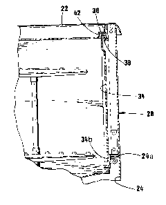
Figures 3 and 4 are partly broken, sectional views taken along
lines 3-3 and 4-4 of figure 2.
DETAILED DE8CRIPTION OF THE INVENTION
Dishwasher 10 includes a large rigid cubic body 12 having
10 a front door vertical opening 14 for loading\retrieving plates,
glasses, forks, and the like in the dishwasher's open baskets or
trays. Body 12 defines two side walls 18, 20, a rear walll a top
wall 22, a bottom wall, and a small lower front wall 24 joining the
front edge 22a of bottom wall to the bottom edge of door opening
15 14. Arcuate hinges 26 are mounted within the front portion of each
side wall 18 for pivoting a large door 28 about a horizontal axis
between a vertical closed position, closing said door opening 14,
and a horizontal open position.
In accordance with the teachings of the invention, the
20 inner face 34 of the dishwasher door 28 defines two spaced
outturned projections 36, 38, extending lengthwisely at the top and
side edge portions thereof and parallel to each other. These
projections 36, 38 therefore define therebetween a continuous U-
shape channel 40, but at a distance from the top, side and bottom
25 edges of the door. The front edge sections 22a, 18a, 20a, of the
top and side walls 22, 18, 20 of the dishwasher main frame 12 each


.......

1 333987
further includes, directly adjacent the inner edges of walls 22,
18, 20, an inturned U-shape cavity 42. These latter cavities 42
again open into each other to form a continuous U-shape channel.
Thus, the door 28 is closed, the door channel 40 engages with the
5 top and side walls' front edge sections' cavity 42, and more
particularly, the outer projecting leg 36 of the door inner wall 34
engages into the hollow of the latter cavity 42.
It is noted that legs 36 are spaced from all the surfaces
of cavities 42 and thus air can freely circulate across the joint
10 but water will not escape because of the interdigitation of the two
joint parts.
The latch member (not shown) that locks the door 28 to
the dishwasher main frame 12 may be of the type shown in my co-
pending application entitled AUTOMATIC DOOR OPENING SYSTEM FOR
15 DOMESTIC DISHWASHER (now Canadian patent No 1,320,412 issued July
20, 1993). However, the latch member may be manually operated to
latch onto a loop member 30, projecting outwardly from the central
portion of the front edge section 22a of the dishwasher top wall 22
upwardly from said top wall front edge 22a, and engaging within a
20 hollow portion 32 made on the central portion of the top end
portion 34a of the door 28.
As illustrated in figure 4, the inner projection 38 on
the inner wall 34 of the door 28 may be cross-sectionally inversely
V-shape, i.e. wider than the outer projection thereof at 36, to
25 prevent biasing engagement of leg 38 into cavity 42 when the door
28 is closed should the door be slightly disaligned on its hinges


.,

1 333987
26.
The bottom end section 34b of inner wall 34 of door 28
should extend below the level of the top edge 24a of lower front
wall 24 (see figure 3), when door 28 is fully closed, again to
5 prevent escape of fluids from the interior of dishwasher 10
outwardly therefrom.


~ ;

Representative Drawing
A single figure which represents the drawing illustrating the invention.
Administrative Status

For a clearer understanding of the status of the application/patent presented on this page, the site Disclaimer , as well as the definitions for Patent , Administrative Status , Maintenance Fee  and Payment History  should be consulted.

Administrative Status

Title Date
Forecasted Issue Date 1995-01-17
(22) Filed 1989-02-08
(45) Issued 1995-01-17
Deemed Expired 2010-01-18

Abandonment History

There is no abandonment history.

Payment History

Fee Type Anniversary Year Due Date Amount Paid Paid Date
Application Fee $0.00 1989-02-08
Maintenance Fee - Patent - Old Act 2 1997-01-17 $50.00 1996-12-20
Maintenance Fee - Patent - Old Act 3 1998-01-20 $50.00 1997-12-23
Maintenance Fee - Patent - Old Act 4 1999-01-18 $50.00 1999-01-07
Maintenance Fee - Patent - Old Act 5 2000-01-17 $75.00 1999-12-22
Maintenance Fee - Patent - Old Act 6 2001-01-17 $75.00 2000-12-18
Maintenance Fee - Patent - Old Act 7 2002-01-17 $75.00 2001-12-20
Maintenance Fee - Patent - Old Act 8 2003-01-17 $75.00 2002-10-30
Maintenance Fee - Patent - Old Act 9 2004-01-19 $75.00 2003-12-08
Maintenance Fee - Patent - Old Act 10 2005-01-17 $125.00 2004-12-24
Maintenance Fee - Patent - Old Act 11 2006-01-17 $125.00 2005-11-14
Maintenance Fee - Patent - Old Act 12 2007-01-17 $125.00 2006-11-28
Maintenance Fee - Patent - Old Act 13 2008-01-17 $125.00 2007-11-16
Owners on Record

Note: Records showing the ownership history in alphabetical order.

Current Owners on Record
ARCHAMBAULT, JEAN
Past Owners on Record
None
Past Owners that do not appear in the "Owners on Record" listing will appear in other documentation within the application.
Documents

To view selected files, please enter reCAPTCHA code :


To view images, click a link in the Document Description column. To download the documents, select one or more checkboxes in the first column and then click the "Download Selected in PDF format (Zip Archive)" or the "Download Selected as Single PDF" button.

List of published and non-published patent-specific documents on the CPD .

If you have any difficulty accessing content, you can call the Client Service Centre at 1-866-997-1936 or send them an e-mail at CIPO Client Service Centre.


Document
Description 
Date
(yyyy-mm-dd) 
Number of pages   Size of Image (KB) 
Office Letter 2000-12-04 1 28
Office Letter 2000-12-04 1 17
PCT Correspondence 1994-10-25 1 34
Prosecution Correspondence 1993-10-20 12 518
Examiner Requisition 1993-08-04 2 94
Prosecution Correspondence 1991-08-30 1 42
Examiner Requisition 1991-06-18 1 59
Representative Drawing 2001-09-12 1 8
Cover Page 1995-01-17 1 14
Abstract 1995-01-17 1 26
Description 1995-01-17 5 169
Claims 1995-01-17 3 89
Drawings 1995-01-17 2 52
Correspondence 2003-12-08 1 39
Correspondence 2004-01-05 1 13
Fees 2003-12-08 2 92
Correspondence 2004-01-30 1 20
Fees 2003-12-08 1 74
Fees 1999-12-22 2 61
Correspondence 2002-10-30 1 42
Fees 2001-12-20 2 105
Fees 1997-12-23 2 69
Fees 2002-10-30 1 109
Correspondence 2000-11-23 3 75
Fees 2000-12-18 2 73
Fees 1999-01-07 2 60
Fees 2004-12-24 1 58
Fees 2005-11-14 1 58
Fees 2006-11-28 2 76
Fees 2007-11-16 1 61
Fees 1996-12-20 2 75