Language selection

Search

Patent 1334842 Summary

Third-party information liability

Some of the information on this Web page has been provided by external sources. The Government of Canada is not responsible for the accuracy, reliability or currency of the information supplied by external sources. Users wishing to rely upon this information should consult directly with the source of the information. Content provided by external sources is not subject to official languages, privacy and accessibility requirements.

Claims and Abstract availability

Any discrepancies in the text and image of the Claims and Abstract are due to differing posting times. Text of the Claims and Abstract are posted:

  • At the time the application is open to public inspection;
  • At the time of issue of the patent (grant).
(12) Patent: (11) CA 1334842
(21) Application Number: 1334842
(54) English Title: SYSTEMS TO DRILL MINERALS ETC...
(54) French Title: SYSTEMES POUR FORCER DES MINERAIS
Status: Expired and beyond the Period of Reversal
Bibliographic Data
(51) International Patent Classification (IPC):
  • E21C 27/10 (2006.01)
  • E21C 25/16 (2006.01)
  • E21C 27/38 (2006.01)
  • E21C 27/40 (2006.01)
(72) Inventors :
  • BECHEM, ULRICH (Germany)
  • BECHEM, KLAUS (Germany)
  • BECHEM, PHILIP (Germany)
  • LENZEN, DIETER (Germany)
(73) Owners :
  • HANNELORE BECHEM
(71) Applicants :
  • HANNELORE BECHEM (Germany)
(74) Agent: SMART & BIGGAR LP
(74) Associate agent:
(45) Issued: 1995-03-21
(22) Filed Date: 1988-03-10
Availability of licence: N/A
Dedicated to the Public: N/A
(25) Language of filing: English

Patent Cooperation Treaty (PCT): No

(30) Application Priority Data: None

Abstracts

English Abstract


System for drilling minerals, rocks and others of
that kind with the use of rotating disk- or slab-
tools, therewith characterized , that the material to
be drilled will be axcavated - as the case may be
pre-cut / reliefed - chiefly in a frontal advance
direction, but also radially from the inside to the
outside - layerwise undercut and always breaking into
the free space. In combination hereto a process-
patent is demanded for a propulsive aggregate being
autonomic by supporting itself on the pre-worked /
pre-cut excavating front - or rather being lead on it
or through it and keeping this way a constant
undercutting depth.


Claims

Note: Claims are shown in the official language in which they were submitted.

THE EMBODIMENTS OF THE INVENTION IN WHICH AN EXCLUSIVE
PROPERTY OR PRIVILEGE IS CLAIMED ARE DEFINED AS FOLLOWS:
1. An apparatus for cutting rock, minerals, and the like
that incorporates a driven shaft on which is arranged at least one
mounting, which supports at least one conical rolling drill on one
side that removes the undercut rock layer by layer in the open
space, characterized in that the rolling drill is connected with a
guide element which spaces this from the face and which supports
the rolling drill on the face during operation and determines the
depth of the undercut.
2. An apparatus as defined in claim 1, characterized in
that a plurality of rolling drills are arranged in several steps.
3. An apparatus as defined in claim 1 or claim 2,
characterized in that the rolling drills have a hammering effect
superimposed on them.

Description

Note: Descriptions are shown in the official language in which they were submitted.


13~8~2
Rocks, and particularly minerals, are normally obtained
by drilling and blasting, with the known disadvantages.
Using the apparatus of the present invention, such
materials can be obtained without the use of explosives and with
an optimal severing effect, and removed layer by layer, preferably
in a linear direction of advance. It has been shown that in the
case of rock cutting by undercutting rock that breaks into open
space, rock pressure assists in obtaining significantly coarser
drilled material which, amongst other things, makes more rapid and
rational drilling possible; in addition, the so-called bore-out
widths or bore-out depths can be selected so as to be considerably
greater depending on the material that is to be drilled, using
comparatively lower contact pressure forces.
The apparatus of the invention can be used for the
expansion of any profiles from the inside outward from an existing
break-in or fore-bore - a round tunnel - to form vault-shaped
profiles, or fore-bores to shafts.
Activation from the inside out means that disks or the
like - with or without serrations can, on the one hand, be
activated from the interior, e.g., by eccentrics, or else the
whole drilling machine can be activated from outside, e.g., by
eccentrics - or acted upon by unbalance-type hammers, and
activated thereby. When this is done, the contact pressure forces
that are required are only about 10% of those required for
conventional drilling.
The self-controlled aggregate not only entails the
advantage that it requires neither control electronics nor an
~. -

133~842
operator to maintain the undercut depth but also that the material
has been drilled out can be easily picked up, i.e., removed,
behind the drilling machine.
In summary, the present invention provides an apparatus
for cutting rock, minerals, and the like that incorporates a
driven shaft on which is arranged at least one mounting, which
supports at least one conical rolling drill on one side that
removes the undercut rock layer by layer in the open space,
characterized in that the rolling drill is connected with a guide
element which spaces this from the face and which supports the
rolling drill on the face during operation and determines the
depth of the undercut.
A preferred embodiment of the present invention will be
described in greater detail below on the basis of the drawings
appended hereto, in which
Fig. 1 is a sectional view of an excavation illustrating
a rotating disk tool;
Fig. 2 is a different sectional view of the excavation
of Fig. 1 illustrating the tool from another angle;
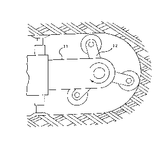
Fig. 3 is a view similar to Fig. 1 but showing a
plurality of cutting disks;
Fig. 4 illustrates a cutting tool for cutting in layers;
Fig. 5 is a detailed view of one of the cutting areas;
Fig. 6 illustrates the use of pre-drilled holes for
drilling arch profiles; and
Fig. 7 shows the arch profile obtained using the
technique illustrated in Fig. 6.

13~842
Figure 1 shows one embodiment wherein 1 refers to the
undercutting, removing and breaking disk-cutter tool, 2 is the
motor-driven, rotating or oscillating arm of the drilling machine,
3 is the outline of the rock before undercutting, and 4 the
outline after undercutting, with the arrow indicating the
direction of advance.
In Figure 2, 7 refers to the disk cutter and 8 is a
rotating or oscillating arm, 9 is the rock front before removal
and 10 the rock front after removal, as in Figure 1, as viewed
from another direction.
In Figure 3, 11 is a conventional advance apparatus and
12 is the drill head with a plurality of disk cutters which, in
this embodiment, is motor-driven; in this, these are arranged in a
line and only undercut/remove one stratum. The drill head can be
activated as a whole, centrally, or the drills can be activated
individually. According to the present invention, in this system,
the specific application forces are unequalled, and thus more
advantageous than with a disk of the diameter of the cutting
height. In Figure 4, 13 indicates the disk drill tools that are
undercutting and rotating, optionally hammering and/or
drilling/hammering tools; 14 indicates the mountings for these,
and 15 is the motor-driven shaft. The tools 13 that are stepped
so as to cut off in the direction of advan~e have mountings that
are of unequal length which are spaced evenly on the shaft 15.
Figure 5 shows the removal front or direction 16 in a stratum, as
viewed from above. In this, which is one of a number of possible
G~ ,,

133484~
embodiments, 17 indicates the traction system, which is a
hydraulic ram with a cylinder that is installed in the top wall or
floor, 18 is a skid, which can also be replaced by wheels or
rollers, or which can be pressed down and locked into position
from one stroke to another, this being done with a separate
disk/advance/traverse system. 19 indicates the pressure system
that is supported so as to be able to pivot on the hydraulic ram -
see arrow 20. 21 is a motor-driven disk-like cutter drill and
21a indicates a similar tool working in a second stage. The
slight angling that is shown reduces wear. The system explained
above can, of course, be used to remove horizontal strata, e.g.,
for the layer by layer removal of road surfaces.
Figures 6 and 7 show how, using the present invention
for undercut removal, it is possible to widen pre-drilled holes
radially from the inside out and, especially, to do this in order
to bore vaulted profiles.
In Figure 6, 29 is the retaining and rotating apparatus
in a fore-bore, 30 is a version of a rolling or hammering disk
cutter as well as a conventional undercutting disk cutter, 31 is
the outline of the rock before undercut removal, 32 is the
extensible, slowly rotating hydraulic cylinder that is driven
through 29 and held from cut to cut without advancing, when
widening a fore-bore.
Figure 7 shows a system for the subsequent drilling out
or widening of a circular tunnel bore to arrive at a vaulted
profile. 33 is a powered optionally activated drill head with
3n

133~842
three disk cutters. 34 is a single activated rolling drill that
can, amongst other things, drill on the spot, which can thus drill
out the corners to form a vaulted profile.

Representative Drawing
A single figure which represents the drawing illustrating the invention.
Administrative Status

2024-08-01:As part of the Next Generation Patents (NGP) transition, the Canadian Patents Database (CPD) now contains a more detailed Event History, which replicates the Event Log of our new back-office solution.

Please note that "Inactive:" events refers to events no longer in use in our new back-office solution.

For a clearer understanding of the status of the application/patent presented on this page, the site Disclaimer , as well as the definitions for Patent , Event History , Maintenance Fee  and Payment History  should be consulted.

Event History

Description Date
Inactive: IPC from MCD 2006-03-11
Time Limit for Reversal Expired 2005-03-21
Letter Sent 2004-03-22
Inactive: Entity size changed 2003-04-03
Inactive: Entity size changed 1999-12-14
Grant by Issuance 1995-03-21

Abandonment History

There is no abandonment history.

Fee History

Fee Type Anniversary Year Due Date Paid Date
MF (category 1, 3rd anniv.) - standard 1998-03-23 1997-10-24
MF (category 1, 4th anniv.) - standard 1999-03-22 1998-11-03
MF (category 1, 5th anniv.) - small 2000-03-21 1999-12-06
MF (category 1, 6th anniv.) - small 2001-03-21 2000-11-28
Reversal of deemed expiry 2001-03-21 2000-11-28
MF (category 1, 7th anniv.) - small 2002-03-21 2001-10-29
MF (category 1, 8th anniv.) - standard 2003-03-21 2003-03-21
Owners on Record

Note: Records showing the ownership history in alphabetical order.

Current Owners on Record
HANNELORE BECHEM
Past Owners on Record
DIETER LENZEN
KLAUS BECHEM
PHILIP BECHEM
ULRICH BECHEM
Past Owners that do not appear in the "Owners on Record" listing will appear in other documentation within the application.
Documents

To view selected files, please enter reCAPTCHA code :


To view images, click a link in the Document Description column. To download the documents, select one or more checkboxes in the first column and then click the "Download Selected in PDF format (Zip Archive)" or the "Download Selected as Single PDF" button.

List of published and non-published patent-specific documents on the CPD .

If you have any difficulty accessing content, you can call the Client Service Centre at 1-866-997-1936 or send them an e-mail at CIPO Client Service Centre.


Document
Description 
Date
(yyyy-mm-dd) 
Number of pages   Size of Image (KB) 
Claims 1995-03-31 1 24
Cover Page 1995-03-31 1 20
Abstract 1995-03-31 1 17
Drawings 1995-03-31 5 104
Representative Drawing 2003-03-21 1 9
Descriptions 1995-03-31 5 151
Maintenance Fee Notice 2004-05-17 1 173
Courtesy - Office Letter 1988-08-26 1 20
PCT Correspondence 1990-04-05 1 42
Courtesy - Office Letter 1989-04-28 1 28
PCT Correspondence 1990-05-09 1 33
Prosecution correspondence 1994-05-16 1 35
PCT Correspondence 1994-12-21 1 30
Prosecution correspondence 1994-02-15 4 115
Examiner Requisition 1993-10-15 3 114
Prosecution correspondence 1991-04-15 2 42
Examiner Requisition 1990-12-13 1 62
Fees 2003-03-21 1 39
Fees 1994-12-21 1 29
Fees 1997-02-13 1 40