Language selection

Search

Patent 1335042 Summary

Third-party information liability

Some of the information on this Web page has been provided by external sources. The Government of Canada is not responsible for the accuracy, reliability or currency of the information supplied by external sources. Users wishing to rely upon this information should consult directly with the source of the information. Content provided by external sources is not subject to official languages, privacy and accessibility requirements.

Claims and Abstract availability

Any discrepancies in the text and image of the Claims and Abstract are due to differing posting times. Text of the Claims and Abstract are posted:

  • At the time the application is open to public inspection;
  • At the time of issue of the patent (grant).
(12) Patent: (11) CA 1335042
(21) Application Number: 1335042
(54) English Title: METHOD OF SECURING PILING LOCKS
(54) French Title: METHODE D'ASSEMBLAGE ETANCHE DE RIDEAUX DE PALPLANCHES
Status: Expired and beyond the Period of Reversal
Bibliographic Data
(51) International Patent Classification (IPC):
  • E02D 5/08 (2006.01)
  • E02D 5/14 (2006.01)
(72) Inventors :
  • PRUCHHORST, MANFRED (Germany)
(73) Owners :
  • HOESCH STAHL AKTIENGESELLSCHAFT
(71) Applicants :
(74) Agent: KIRBY EADES GALE BAKER
(74) Associate agent:
(45) Issued: 1995-04-04
(22) Filed Date: 1989-05-02
Availability of licence: N/A
Dedicated to the Public: N/A
(25) Language of filing: English

Patent Cooperation Treaty (PCT): No

(30) Application Priority Data:
Application No. Country/Territory Date
P 38 15 236.3-25 (Germany) 1988-05-05

Abstracts

English Abstract


A method of securing piling locks in order to transmit thrust.
An adhesive is applied between the surfaces of the interlocking
halves of the lock that come into contact with each other in the
inside of the lock.


Claims

Note: Claims are shown in the official language in which they were submitted.

CLAIMS
1. A method for securing piling locks for transmitting
an external thrust applied against one pile to adjacent piles,
comprising the steps: providing at least a first pile and a
second pile each with interlocking elements; applying adhesive
to said interlocking elements of said first pile along surfac-
es of said elements to be contacted by corresponding mating
interlocking elements on said second pile; placing a caliber
member on the interlocking elements of said first pile to
protect said adhesive and prevent soil from reaching the
surfaces with adhesive thereon while said first pile is driven
in; driving in said first pile with said caliber member in
place; removing said caliber member from said first pile by
drawing said caliber member upwards and out of the interlock-
ing elements of said first pile after said first pile has been
driven in; threading and meshing the interlocking elements of
said second pile into the interlocking elements of said first
pile; driving in said second pile; hardening said adhesive
between contacting surfaces of the interlocking elements of
said first pile and said second pile to form a force-fitted
joint with said contacting surfaces extending grippingly into
one another and cemented together by said adhesive and to hold
the interlocking elements fixedly together so that said piles
are not shiftable relative to one another, an external thrust
applied to one pile being transmitted to the other adjacent
pile through said interlocking elements for resisting said
thrust by a plurality of piles.
- 5 -

2. A method for securing piling locks for transmitting
an external thrust applied against one pile to adjacent piles,
comprising the steps: providing at least a first pile and a
second pile each with interlocking elements, the interlocking
elements of said first pile having a bottom; closing said
bottom of said interlocking elements of said first pile;
placing a caliber member having a pipe with nozzles mounted
thereon on the interlocking elements of said first pile to
prevent soil from reaching surfaces on said interlocking
elements of said first pile to be contacted by corresponding
surfaces of the interlocking elements of said second pile;
driving in said first pile with said caliber member in place;
applying adhesive through said nozzles to said interlocking
elements of said first pile along said surfaces to be contact-
ed by corresponding mating interlocking elements of said
second pile; extracting said caliber member from said first
pile by drawing said caliber member upwards and out of the
interlocking elements of said first pile while said adhesive
is being applied simultaneously to said surfaces by said
nozzles; threading and meshing the interlocking elements of
said second pile into the interlocking elements of said first
pile; driving in said second pile; hardening said adhesive
between contacting surfaces of the interlocking elements of
said first pile and said second pile to form a force-fitted
joint with said contacting surfaces extending grippingly into
one another and cemented together by said adhesive and to hold
the interlocking elements fixedly together so that said piles
are not shiftable relative to one another, an external thrust
applied to one pile being transmitted to the other adjacent
pile through said interlocking elements for resisting said
thrust by a plurality of piles.
- 6 -

Description

Note: Descriptions are shown in the official language in which they were submitted.


C A l 3 35042
1 METHOD OF SECURING PILING LOCKS
2 '~he invention concerns a method of securing piling locks ih
3 order to transmit thrust, whereby an adhesive is applied
4 between the surfaces of the interlocking halves of the lock
that come into contact with each other inside it. The
6 securing process is intended to prevent the sheet piles from
7 mutually sliding back and forth.
9 Sheet piles are usually not driven in individuall~ but are
previously combined at the factory into double or triple
11 sheets called driving units. Securing together the locks on
12 sheet piles that are combined into such units at the factory
13 by welding or crimping is known. It is, however, impossible
14 to secure the driving-unit locks, the locks applied to the
driving units to connect them together on site, in this way.
16 It is technically impossible to unexceptionably weld the
~7 driving-unit locks together to prevent them from slipping
18 below the ground level of a harbor, canal, or building-
19 excavation construction site or below the water level of a
canal, river, or harbor, and the finished weld will not
21 fulfill its purpose subject to the load that is typical for
22 sheet piling.
23
24 A method of manufacturing multiple sheet piles whereby the
locks applied in the factory are secured to each other with
26 adhesive to prevent them from sliding is known (German AS 2
27 002 799). Once the adjacent locks have been hooked together,
28 the longitudinal outer gaps are sealed to allow the pres-
29 surized injection of an adhesive inside them and the overall
connection is maintained motionless until the adhesive can
,' ' ~.
., ' ~

. .-^7
, ~,
1 335042
1 cure. This procedure, however, can only be carried out at
2 the factory.
4 In another known method, a curing mass is introduced by means
of a hose or pipe that extends to the bottom of the par-
6 ticular hollow space (German OS 3 041 440). The purpose is
7 to create a wall that will block out soil and/or water.
9 The object of the present invention ls to improve a method of
the type initially described to the extent that it can be
11 employed not only with the locks on the driving units
12 connected together at the factory but also with the driving-
13 unit locks, ensuring unexceptionable transmission of thrust
14 in the on-site threaded lock.
16 The method employed to attain this object in accordance with
17 the invention consists of introducing the adhesive into the
18 forward half of the lock before the driving unit is driven
19 in, applying a caliber piece to the half to protect the
adhesive and keep soil out of the inside of the lock, and
21 extracting the caliber piece once the driving unit has been
22 driven all the way in. This characteristic of the method in
23 accordance with the invention makes it possible to apply the
24 adhesive even below the water table or in the open water.
26 The curing time can be decelerated or accelerated either
27 above or below the water, depending on the type of adhesive.
28
29 The adhesive preferably consists of an environmentally safe
and combustion-resistant material, and also of cement or
'~
'~p.

1 3 ~ 2
1 mixtures of cement for example.
3 In addition to unexceptionably securing the piling locks
~ together, the method in accordance with the invention also
seals the sheet piling very tight, so that no additional
6 measures are necessary to seal it.
8 Another characteristic of the method in accordance with the
9 invention consists of applying a c~l;her piece that has a
pipe with nozzles mounted on it to the forward half of the
11 lock before the driving unit is driven in and of extracting
12 the caliber piece while simultaneously injecting the adhesive
13 through the nozzles on the pipe once the dri~ing unit has
14 been driven all the way in.
16 The invention will now be described in detail with reference
17 to the drawing, which consists of top views of different
18 piling locks, whereby
19
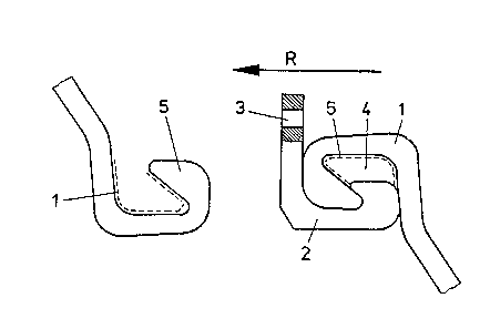
Figure 1 shows the halves of a lock that connects
21 two driving units, next to each other,
22
23 Figure 2 shows the forward half of a lock on one
24 driving unit, and
6 Figures 3 to 7 each show a sheet-piling lock.
27
28
29 Inserted into the forward half 1 of the sheet-piling lock
illustrated in Figure 1 is a caliber piece 2 that has a bore
. ~ ~
." . .~,

1 335~42
1 3 for extracting the caliber piece. Caliber piece 2 protects
2 the adhesive inserted before the unit is driven in and keeps
3 soil out of the inside 4 of the lock. The broken line along
4 the inside of forward half 1 represents the later position of
the other half 5 and the broken line along the inside of half
6 5 the later position of half 1. The pile-driving direction
7 is indicated by arrow R.
9 Figure 2 illustrates how the adhesive can be introduced once
the piles have been driven in. A caliber piece 2.1 is
11 inserted in the forward half 1 of a driving unit 6. Mounted
12 on the caliber piece is a pipe 7 with nozzles 8. During the
13 pile driving, caliber piece 2.1 is positioned down to the
14 final depth along with pipe 7 and its nozzles 8. The
adhesive is injected into the inside 4 of the lock through
16 nozzles 8 while caliber piece 2.1 is subsequently being
17 withdrawn. The sheet-piling lock is closed off at the
18 bottom.
19
The position of the sheet-piling lock illustrated in Figure
21 3 is ideal and has the requisite amount of play.
22
23 The sheet-piling locks illustrated in Figures 4 through 7
24 exhibit actual positions, with the particular contact
surfaces, the active adhesive areas, that is, inside the lock
26 indicated by hatching. The illustration is intended to show
27 that there will be sufficient adhesive area in any conceiv-
28 able position of the lock.
29
-- 4 --

Representative Drawing
A single figure which represents the drawing illustrating the invention.
Administrative Status

2024-08-01:As part of the Next Generation Patents (NGP) transition, the Canadian Patents Database (CPD) now contains a more detailed Event History, which replicates the Event Log of our new back-office solution.

Please note that "Inactive:" events refers to events no longer in use in our new back-office solution.

For a clearer understanding of the status of the application/patent presented on this page, the site Disclaimer , as well as the definitions for Patent , Event History , Maintenance Fee  and Payment History  should be consulted.

Event History

Description Date
Time Limit for Reversal Expired 2006-04-04
Inactive: IPC from MCD 2006-03-11
Letter Sent 2005-04-04
Inactive: Late MF processed 2003-07-30
Letter Sent 2003-04-04
Grant by Issuance 1995-04-04

Abandonment History

There is no abandonment history.

Fee History

Fee Type Anniversary Year Due Date Paid Date
MF (category 1, 3rd anniv.) - standard 1998-04-06 1998-03-19
MF (category 1, 4th anniv.) - standard 1999-04-05 1999-03-18
MF (category 1, 5th anniv.) - standard 2000-04-04 2000-03-13
MF (category 1, 6th anniv.) - standard 2001-04-04 2001-03-19
MF (category 1, 7th anniv.) - standard 2002-04-04 2002-03-20
MF (category 1, 8th anniv.) - standard 2003-04-04 2003-07-30
Reversal of deemed expiry 2003-04-04 2003-07-30
MF (category 1, 9th anniv.) - standard 2004-04-05 2004-03-31
Owners on Record

Note: Records showing the ownership history in alphabetical order.

Current Owners on Record
HOESCH STAHL AKTIENGESELLSCHAFT
Past Owners on Record
MANFRED PRUCHHORST
Past Owners that do not appear in the "Owners on Record" listing will appear in other documentation within the application.
Documents

To view selected files, please enter reCAPTCHA code :


To view images, click a link in the Document Description column. To download the documents, select one or more checkboxes in the first column and then click the "Download Selected in PDF format (Zip Archive)" or the "Download Selected as Single PDF" button.

List of published and non-published patent-specific documents on the CPD .

If you have any difficulty accessing content, you can call the Client Service Centre at 1-866-997-1936 or send them an e-mail at CIPO Client Service Centre.


Document
Description 
Date
(yyyy-mm-dd) 
Number of pages   Size of Image (KB) 
Cover Page 1995-04-12 1 19
Claims 1995-04-12 2 93
Abstract 1995-04-12 1 10
Drawings 1995-04-12 2 31
Representative Drawing 2003-03-21 1 5
Descriptions 1995-04-12 4 160
Maintenance Fee Notice 2003-05-05 1 174
Late Payment Acknowledgement 2003-08-21 1 167
Maintenance Fee Notice 2005-05-30 1 172
Fees 2003-07-30 1 39
Fees 1997-03-20 1 61
PCT Correspondence 1995-01-09 1 35
Prosecution correspondence 1994-08-03 2 78
Examiner Requisition 1994-05-05 2 77
Prosecution correspondence 1992-05-20 2 52
Examiner Requisition 1992-03-02 1 53