Note: Descriptions are shown in the official language in which they were submitted.
1 33~2~0
IMPROVED ACTIVE SPALL SUPPRESSION ARMOR
CROSS REFERENCE TO RELATED APPLICATION
The present invention is an improvement over
that disclosed in Musante et al Canadian Application
Serial No. 575,460 entitled ACTIVE SPALL SUPPRESSION
ARMOR.
BACKGROUND OF THE INVENTION
Field of the Invention
The present invention relates to the reduction
of injury and damage from the spall typically generated
off the inside surface of armor plate or the like, by
contiguously attaching light weight spall backing
material having a sonic impedance such that the stress
reflected into the armor is below that which causes
significant spallation in the armor. The lightweight
backing is frangible or of low strength such that when it
fractures, the particles are of low mass and/or kinetic
energy and of minimal concentration capability.
Description of the Prior Art It is well
recognized that spall is a primary cause of armor vehicle
kills during combat. Spall may be characterized as a
cloud of high velocity fragments of metal which is
released from the inside surface of the vehicle's armored
hull and is lethal to soft targets inside the vehicle.
The soft targets include electrical cables, electrical
components, fuel lines, fuel cells, and personnel within
the vehicle.
Spall liners consisting of aramid fiber
reinforced polymer panels are currently being used for
minimizing the spall effect, but are quite expensive and
heavy. Application of these liners is hindered by
limited space in vehicles and the low space efficiency of
the liners. The effectiveness of these liners require
that the liners be spaced from typically about 4 to 17
inches from the inner wall of the vehicle and are
therefore undesirable since the useable space within most
vehicles
~,"
-2_ l 335240
is quite limited. Also, the hardware within the vehicles
makes it difficult or impossible to secure the liner
within all portions of the vehicle without interfering
with the operation and location of vehicle components.
Significant areas in vehicles, such as turret and driver
areas, have spall protection which is either limited or
non-existent due to lack of space for any standoff.
SUMMARY OF THE INVENTION
In general, active spall suppression armor
includes an armor material or plate backed by a spall
backing material which is contiguously attached to the
inside surface of the armor, typically by adhesives. The
spall backing material may be of the consistency of
pliable putty, or may be in the form of hard, soft, or
elastic tiles or sheets. In the event that the spall
backing consists of a uniform dispersion of particles in a
binder matrix, the matrix binder may serve to contiguously
adhere the backing material to the armor. The spall
material when fractured, due to stresses transmitted
through the armor material, forms nonlethal fragments of
low mass and kinetic energy. The sonic impedance of the
spall material is such that the stress reflected by the
spall backing material into the armor is below that which
causes failure in the armor, which failure would result in
lethal spall particles being propelled from the inner
surface of the metal armor. Spall may be created in the
backing material but the effect is minimized by assuring
that the spall created in the backing material has low
energy and is therefore of limited penetration
capability. The armor material may be steel armor,
aluminum armor, and other types of armor including
composite materials.
The improved active spall suppression armor is
directed to the use of different types of either
monolithic or composite materials in contact with the
3 l 3 3 5 2 ~ 0
armor plate, used alone or with a secondary layer or
plate spaced therefrom.
In particular, the improved active spall
suppression system performs better than present spall
liners where minimal space is available, typically under
four inches.
According to an aspect of the present
invention, an apparatus for suppressing spall from
being created on the inside surface of metal armor when
the outside surface is being subjected to an impulse load
from a weapon causing a compressive stress and shock wave
to be applied through the thickness of the armor,
comprises:
means defining a primary powder loaded
composite spall backing material which if fractured due
to stress transmitted through the metal armor will form
particles of low mass, low kinetic energy and low
penetration capability, said spall backing material
having a sonic impedance relative to the sonic impedance
of the metal armor such that the stress reflected into
the armor by the backing material at least suppresses the
formation of significant spall in the armor; and
means for maintaining said spall backing
material in contiguous contact with said inner surface of
said metal armor.
According to another aspect of the present
invention, a spall suppression composite elastomeric
matrix backing material as an article of manufacture
comprises:
an elastomer in said matrix; and a metal powder
loaded in said elastomer.
BRIEF DESCRIPTION OF THE DRAWINGS
Figure 1 is a perspective in section
illustrating an armor plate without spall backing
material attached thereto being impacted by a shaped
charge, or projectile, and showing armor spall being
discharged therefrom.
3a 1 335240
Figure 2 is a diagrammatic elevation of a
military vehicle illustrating a projectile passing
through the two armor walls and two spall liners of a
prior art vehicle illustrating spall cone angles.
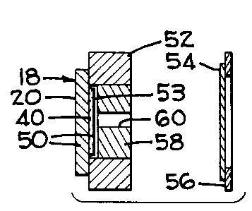
Figure 3 is a diagrammatic elevation in
vertical section illustrating an armor plate with spall
backing material attached to a test stand, and a witness
sheet attached to a frame.
Figure 4 is a diagrammatic elevation
illustrating a saw-toothed stress wave created in the
armor by the impact of a shaped charge explosive at four
separate time intervals relative to the free inner
surface of the metal armor.
Figure 5A is a diagram illustrating the saw
toothed stress waves at an interface between an armor
plate and a backing material having a lower sonic
impedance than that of the armor plate.
Figure 5B is a diagram illustrating the
saw-toothed stress waves at an interface between an armor
plate and a backing material having a greater sonic
impedance than the armor plate.
Figure 6 is a vertical section taken through an
armor plate having a spall backing material contiguously
- _4_ l 3 3 5 2 ~ O
attached thereto by an optional interlayer.
Figure 7A is a copy of a photograph
illustrating the back of an armor test plate without spall
backing illustrating the area from which armor spall has
been released and further illustrating a hole therein
formed by the shaped charge jet.
Figure 7B is a copy of a photograph
illustrating the front of a witness plate illustrating the
usual pattern of holes formed therein from spall from the
armor plate of Figure 7A and the slug from the shaped
charge slug, respectively.
Figure 8 is a vertical section through an
improved single layer spall suppression system, the dotted
lines indicating that the backing material may be used in
the form of a single plate or a plurality of plates.
Figure 9 is a vertical section through an
improved double layer spall suppression system similar to
Figure 8 but having a secondary plate or sheet spaced from
the backing material.
Figure 10 is a copy of a back lighted
photograph of the front of a witness plate, at reduced
scale, illustrating the results of a TOW ll shot through
an unbacked armor plate of 1.75- 5083 aluminum and showing
the usual circular pattern of holes formed from lethal
spall and a central hole formed by the jet and slug of the
weapon when shot at 0.
Figure ll is a copy of a back lighted
photograph with test conditions the same as Fig. 10 but
of a witness plate illustrating the results of a test shot
through an armor plate backed by a single layer of 4.5 PSF
aramid fiber backing material at 4- spacing and showing a
hole formed by the slug but very few holes formed by
spall.
Figure 12 is a copy of a back lighted
photograph of the front of a witness plate with test
~ - 5 13352~0
conditions the same as Figure 10 but illustrating the
results of a test shot through the armor plate having a
4.3 PSF single layer of backing material attached
thereto, and a hole formed by the slug with a slightly
larger amount of holes formed by spall.
Figure 13 is a copy of a back lighted
photograph of the front of a witness plate with test
conditions the same as Figure 10 but illustrating the
results of a shot through the armor plate having a 2.8
PSF single layer of primary backing material attached
thereto and a 1.5 PSF aramid fiber plate spaced 2 inches
from the primary backing material showing the hole formed
by the slug plus two holes of lethal spall believed to be
formed by fragments from the slug.
DESCRIPTION OF THE PREFERRED EMBODIMENT
In order to better understand the improved
active spall suppression armor of the present invention,
Applicant, who is a co-inventor of cross-referenced
Canadian Application Serial No. 575,460, has included
herein the general theory of operation along with
definitions of terms, formulas, tables and sample
calculations which appear in the cross-referenced
application. The improved armor of the present invention
begins at the title IMPROVED ACTIVE SPALL SUPPRESSION
ARMOR.
Prior to describing the active spall
suppression armor 18 of the present invention, it is
believed that a brief description of spallation would be
helpful.
Figure 1 diagrammatically illustrates a section
of metal armor 20, without a spall backing material
attached thereto, being contacted by a weapon 22 which
may be a shaped charge or a high velocity projectile.
The weapon 22 contacts an outer surface 23 of the armor
with sufficient force to dislodge spall fragments 24 from
the free or inner surface 26 of the armor 20. The spall
- _ 1 33524~
--6--
fragments are propelled from the inner surface 26 of the
armor along a conical path of about 100 at high velocity
with many of the fragments being of sufficient mass to be
highly penetrating to soft targets that are contacted by
the fragments. More particularly, spalling is a failure
mode wherein fracture occurs near the free surface 26
(Fig. 1) remote from the outer surface 23 where an impulse
load is applied. The impulse load is typically generated
by an explosive detonation from a shaped charge, or by the
impact of a high velocity projectile. The impulse induces
a compressive shock wave which propagates to the opposite
free surface 26 where it reflects as a tensile wave. The
intensity of the tensile wave will increase as it
propagates back through the material. At some distance
15 from the surface 26, the stress intensity exceeds the
threshold required for initiation and fracture at which
time spallation occurs discharging the spall 24 inwardly
at high velocity.
Figure 2 diagrammatically illustrates a
20 vertical section through two armor plate walls 28,29 of a
vehicle having two prior art spall liners 32,34 spaced
inwardly of the vehicle. The path 36 of the projectile is
illustrated by arrows as passing through both walls 28,29
and liners 32,34. However, a primary spall cone angle in
25 the first contacted wall 28 indicates that the first spall
liner 32 stops some spall but allows larger high velocity
pieces to pass through and be stopped by a second spall
liner 34 as illustrated by a narrow secondary spall cone
38.
Figure 4 represents stresses caused by shaped
charge weapons and illustrates the formation of
compressive and tensile waves when passing through the
first contacted armor at four separate time intervals to
the free surface 26 without spall backing material
35 attached thereto. At time T-l a saw-tooth wave or pulse
-7~ ~ 335240
39 illustrates the stress intensity relative to the back
or inner surface 26 of the armor caused by the detonation
of an explosive. As illustrated at time T-2, when the
compressive wave 39 reaches the free surface 26 it
5 reflects as a tensile wave 42, which is partially
cancelled by the incident compressive pulse 39. The
tensile stress will increase until the maximum stress
occurs at a distance from the surface 26 of the plate 20
equal to one-half of the pulse length as indicated at time
T-3. At time T-4 the intensity of the tensile wave
exceeds the compressive wave thus indicating that spall
will not be created.
When a projectile, as opposed to an explosive
detonation or a shaped charge, applies the impact load, a
square wave (not shown) is produced which will provide no
tensile stress until the maximum occurs at the half pulse
distance at T-3 of Figure 4.
The creation of spall fracture is dependent
upon both the magnitude and duration of stress.
Sufficient time at the sufficient stress are required to
first nucleate cracks, and then to grow the cracks.
Fracture is therefore dependent upon amplitude and the
shape of the stress pulse. When the condition of stress
intensity and time are such that the criterion for
fracture are met, then the spall will be formed. When
fracture occurs, the strain energy remaining in the
material between the fracture and the rear face is
released as kinetic energy and the spall particles fly
from the rear face, usually with significant velocity.
The velocity is limited theoretically by the equation: V
= 2M/DC where M is the magnitude of the stress wave, D is
the density of the material, and C is the material sound
speed.
Interaction of Stress Waves at Interfaces
When a stress wave encounters an interface or
- 1 3352~0
--8--
free surface between two dissimilar materials such as the
armor plate material 20 (Figs. SA,5B and 6) and the spall
backing material 40, the stress waves behavior becomes
more complex. The simplest situation is a normal impact
by a projectile with a diameter of the same order of
magnitude as the armor plate thickness. The stress wave
can then be considered to have a planar front and to
travel perpendicular to the face of the plate. In
general, when this wave reaches an interface, one wave is
reflected and another is transmitted. The intensities of
the waves are dependent upon the relative sonic impedances
of the two materials.
The sonic impedance (z) of a material is the
product of the sound speed (c) in the material, and its
density (D). The values of density and sound speed are
not constant, but vary to some degree with pressure.
Consequently, impedance can vary with the pressure and
will definitely change when the yield strength of a
material is exceeded. Generally, for most fully dense,
elastic materials, the impedance below the yield point is
relatively constant. The density, sound speed, and
impedance are listed in Table l for a number of common
materials. The intensities of the transmitted and
reflected waves from a stress wave impinging an internal
interface are given by the following equations:
A
R = I(D2 C2 - Dl Cl) / (D2 C2 + Dl Cl)
and;
T = I(2Dl Cl) / (D2 C2 ~ Dl Cl)
or;
R = I(Z2-Zl) / (Z2 + Zl)
and;
T = I(2Zl) / (Z2 ~ Zl)
where;
1 33524û
g
R = REFLECTED WAVES
T = TRANSMITTED WAVES
I = INCIDENT WAVES
z = IMPEDANCE OF THE MATERIAL
D = DENSITY
and where subscript;
1 = the armor material
2 = the spall backing material
By convention, compressive stress has a
positive value and tensile stress has a negative value.
From the above equations, a compressive wave
will reflect as a tensile wave in the armor material if
the second layer or backing material has a lower
impedance, as illustrated in Figure 5A; and as a
compressive wave if the backing material has a higher
impedance as illustrated in Figure 5B. The amplitude of
the reflected tensile wave will always be less than or
equal to that of the incident compressive wave.
The relative intensity of the reflected wave in
the armor material is related to the relative impedance of
the spall backing material as follows:
For an impedance ratio (n) of the armor
material the following equations apply: n = Z2/zl
R/I = (Z2 Zl) / (Z2 + Zl) = nZl - Zl / (nZl + Zl)
or;
R/I = (n-l) / (n+l)
This ratio is tabulated in Table 2 to
illustrate how a second layer, or backing material 40
(Fig. 6), can be used to reduce the magnitude of the
reflected stress. It can be seen that a material with
only one-fifth of the impedance of the first layer (armor
material) can reduce the reflected tensile stress by as
much as 33 percent.
1 335240
--10--
TABLE 1
Density D, sound speed (C) and Impedance values t2) for
selected materials.
D C Z
~AT'L (lb/ft3) ~k ft/s) (k lb/ft2sec x 105)
Aluminum 88.6 17.8 1.58
6061-$6 Aluminum 88.7 17.1 1.52
2024 Aluminum 91.4 17.2 1.57
Berylliun 60.7 26.5 1.61
10 Brass 276.6 12,2 3.36
Boron Carbide(?S~ Dense) 63.0 9.7 0.61
Silicon Carbide(72~ Dense) 76.19.4 0.71
Tung~ten Carbide492.8 17.0 8.38
Carbon Phenolic 48.9 13.8 0.67
lS Chromium 233.6 17.4 4.06
Cobalt 289.4 15.7 4.56
Copper 293.0 12.9 3.77
Epo~y 39.4 8.8 0.34
Graphite (Commercial) 53.4 4.8 0.26
20 Pyrolitic Graphite72.2 13.6 0.98
Armco rron 257.6 14.8 3.80
Lucite 38.7 7.2 0.28
Magnesium 57.3 14.9 0.85
~anganin 277.6 12.5 3.46
25 Mylar 45.6 7.2 0.33
Nickel 290.7 15.3 4.44
Nylon 37.4 7.1 0.26
Paraffin 30.1 9.7 0.29
Phenolic ~iberglass(A~CO) 62.3 5.6 0.35
30 Phenolic Eiberglass (GE) 63.7 10.7 0.68
X-Cut Crystalline Quartz 86.9 18.8 1.63
Plexiglass 38.9 9.0 0.35
Polyethylene 30.2 9.6 0.29
-11- 1 3 3 5 2 ~ O
D C Z
_A~'L (lb/ft3) (k ft/~) (k lb/ft2sec x 105
Polystyrene 34.5 9.8 0.34
Polyurethane ~1.5 6.8 0.28
304 SS 259.1 15.0 3.87
~ild Steel (EN3) 257.2 11.8 3.03
Seflon 70.9 4.7 0-33
Sin 238.9 8.4 2.02
Titaniu~ 148.0 15.4 2.28
Tungsten 629.0 13.0 8.19
Uraniu~/3t ~oly. 605.3 8.4 5.07
- Sinc 234.3 10.0 2.35
Zirconiu~ 213.4 12.3 2.63
SA~LE 2
Reduction in the reflected tensile stress for a
given relative i~pedance of a layer of backing ~aterial.
I~pedance ~ Reduction in
Ratio n Reflected Tensile Stres~
________________________________________________
.10 18
.20 33
.30 46
.40 57
.50 67
.60 75
82
.80 89
.90 95
1.00 100
-12- 1 3 3 5 2 4 0
When the spall suppression armor 18 (Fig. 6) of
the present invention is to be used on light weight
armored vehicles, as well as heavy armored vehicles, it is
of course desirable to minimize any added weight to the
vehicle. Accordingly, the spall backing material is not
designed to completely suppress fractures in the spall
backing material 40 by all known weapons but is designed
to provide backing material which, if fractured, will
fracture into low energy, particles of low penetration
capability when the armored plate and backing material are
contacted by a weapon, either a shaped charge weapon or a
projectile. It is, of course, understood that the backing
material may be thickened or be in layers of the same oc
different backing materials if added weight is not a
problem.
The concept of the subject invention involves
the backing of armor plate 20 with a backing material 40,
or a series of backing materials, which must satisfy two
conditions. First, the impedance of the backing material
must be such that the stress reflected into the armor
plate 20 is below that which would cause spall-type
failure in the armor plate. Second, the fragments from
the fracture of the backing material, caused by
transmitted stress, must be nonlethal, that is, of low
mass and/or velocity. Varying impedance in the backing
material may be used to condition the stress wave in the
backing material to control fragmentation. The impedance
may be varied by either layering or by controlling the
material properties continuously through their thicknesses.
A preliminary design analysis was made for
identifying the relationship between design variables and
system weights. First, the amount of the stress wave
which must be transmitted into the spall backing material
was estimated by comparing spall strength to the stresses
involved in jet penetration. With this data, the
- 1 335240
-13-
properties of the spall backing material was determined.
The weapons used were shaped charge TOW-II with
a jet impacting aluminum armor. A 200 GPa (giga pascals )
shock stress was generated with a pulse time length of
1.175 microseconds, which shock stress was calculated from
the jet diameter divided by the sound speed in 5083 for
MIL-A-46027G(MR) aluminum having a thickness of one inch.
It was assumed that the aluminum had about the same spall
~strength~ as steel, the stress is so much higher in the
aluminum than its strength, that essentially the full
amplitude of the stress wave must be transmitted into the
backing material.
The relationship between the impedance of the
backing material 40 and the areal density AD required to
suppress spall in the aluminum armor was derived as
follows:
Let:
= stress pulse wavelength in the backing material
Ial = stress pulse wavelength in the aluminum
20 cns = wave velocity in the backing material
cal = wave velocity in the aluminum
th = minimum thickness of any backing material for
passage of the full stress wave
d = diameter of the shaped charge jet
25 DnS = density of the backing material
tal = time length of the stress wave in the aluminum
Zns = sonic impedance of the backing material
ADX = minimum areal density of backing material ~x~
for passage of the full stress wave
The wavelength of the stress pulse in the aluminum armor
can be estimated by:
tal = d/cal
Ial = talcal = d
The wavelength in the backing material is:
35 InS Ial(Cns/cal)
-14- 1 3 3 5 2 4 0
Assuming that the backing material will separate from the
aluminum when the stress wave reaches the interface after
reflecting in tension from the backface of the backing
material (because the interface cannot support significant
tensile stress), and that conservatively, the whole wave
should pass into the backing material:
Ins = 2th or th = (1/2)Ins
Combining the above three equations gives the minimum
backing material thickness for any given material:
th = (d/2)Cns/cal
The minimum areal density (AD) of the backing system can
be calculated as follows:
AD = Dnsth D nS[(d/2)cns/cal] (Equation 1)
= Dnscns[(d/2)cal]
Since Zns =DnScns
AD = ZnS[(D/2)cal] (Equation 2)
Since the jet diameter, d, and the aluminum wave velocity,
cal, are constant for any given case, the minimum areal
density of a backing system is linearly related to its
impedance. If again it is conservatively assumed that
there must be no reflected tensile wave in the aluminum,
then the optimum backing material areal density will be
when the Impedance of the backing material matches that of
the aluminum.
Sample calculationS
Assuming a 3/8 inch jet diameter vs. aluminum armor with
aluminum as a backing material (matched Impedance),
optimum areal density can be calculated as follows:
Using equation (1):
ADal = Dal[(d/2)(cal/cal)] = Dal(d/2)
For aluminum, DnS = 14 lb/ft2, which yields:
ADal = 2.625 lb/ft2
-15- 1 3 3 5 2 4 0
The fired alumina, which worked well in the preliminary
testing, would yield an optimum from equation (2)
(considering that Zalumina/Zal = 2-33)
alumina = 2-625(2.33) = 6.116 lb/ft2
The above calculations indicate that aluminum would be a
lighter backing material than the fully-fired alumina.
However, the aluminum is not frangible. While the
aluminum backing material would successfully extract the
stress wave from the aluminum armor plate or hull
structure of a vehicle, the aluminum backing material
could itself produce highly penetrating spall.
This design methodology also suggests the
merits of a metallic or ceramic particle loaded polymer.
In this case, the individual particles may have a higher
sonic impedance than that of the armor. However, when the
particles are combined with a polymer, the particle
content must be sufficient to insure that the
particle/polymer blend has an impedance value sufficient
to reduce the reflected tensile stress below that required
to form spall. A particle/polymer blend may also afford
the advantage of sticking directly to the armor without
the need of an intermediate adhesive.
A low density strength solid which fractures in
a brittle manner, and which has a suitable impedance, may
also be used. For instance, solid, polycrystalline sodium
chloride (NaCl) in a 1/2 inch thickness has suppressed
spall formation in aluminum armor when bonded to the back
of the armor plate.
Tests have been conducted to investigate the
effect of spall backing material thickness, warhead size,
obliquity, armor alloy, and armor thickness on the
performance of the various backing materials. The general
procedure consists of adhesively bonding the backing
material 40 (Fig. 6) to the armor plate 20 which together
comprise a piece of active spall suppressive armor 18 in
~ -16- 1 335240
the form of a target 50 (Fig. 3). The target is fixed to
a test stand 52, and the target 50 and a witness sheet 54
are subjected to a warhead attack. Base line targets of
unbacked and liner-backed armor plates were also tested
for comparison purposes. The witness sheets 54 were
placed behind the test stand to record the distribution of
spall and jet particles.
-
-17- l 3 3 5 2 4 0
THE IMPROVED ACTIVE SPALL SUPPRESSION ARMOR
The improved active spall suppression armor of
the present invention discloses two systems for
suppressing the formation of spall. A first system is a
single layer system 80 (Fig. 8) which uses a single layer
(or two or more thin plates to make up the single layer)
of several preselected types of spall backing material 82
that is preferably bonded to the inner wall 84 of armor
plate 86 (sometimes referred to as the target) by an
interlayer 88 of adhesive. The material used to form the
spall backing system differs from those previously
described and provides improved spall suppression with
spall backing materials of reduced weight.
The second system is a double layer system 90
(Fig. 9) which bonds the same type of spall backing
material 82a to the armor plate 86a by an interlayer 88a
of adhesive. In addition, the second system includes a
second plate or liner 92a spaced from the spall backing
material 80a for defeating secondary particles of the jet
and armor which are disturbed from the penetration
interface by the presence of the active spall suppression
backing.
In the single layer system 80 (Fig. 8) the
primary spalL backing material 82 is placed in contact
with the armor plate 86 and may be bonded thereto if
desired by the interlayer 88 of adhesive. Alternately,
the tacky nature of the polymer matrix of the backing
material may be used as an adhesive if applied to the
backing material before it is cured. Before curing, the
backing material may be sprayed or troweled onto the armor
plate. Alternately, the polymer matrix backing material
may be cast into plates, allowed to cure, and thereafter
be bolted to the armor plate 86. The spall backing
material is formed of materials such that the composite
-18_ 1 3 3 5 2 4 0
backing was an impedance which is tailored so that the
tensile stress is reduced below that required for spall
formation. Therspall backing material breaks up into
fine, low energy, non-penetrating fragments after
absorbing the shock wave.
The spall backing materials tested in the
cross-referenced co-pending application were primarily
alumina-type ceramics, whereas the spall backing material
of the present invention are primarily metal and ceramic
powder loaded polymer composites.
DISCUSSION OF THE SPECIFIC PROBLEMS
Spall generated from armor plate used on combat
vehicles, as a result of being overmatched by shaped
charge or projectile attacks, is perhaps the largest
contributor to casualties and fire power kills. Spall
consists of a cloud of high velocity fragments ejected
from the back surface of an armor plate due to an impact
on the front surface. The present state-of-the-art method
for prevention of damage from spall is to place aramid
fiber reinforced plastic liners (sometimes referred to as
panels or plates) behind the armor in order to catch the
spall particles. These liners, specified for application
in armored personnel carriers and fighting vehicles,
require significant space for crew member efficiency and
for mounting hardware to the inner vehicle surfaces, and
have limited ability to function after a single hit.
The space aspects are especially important in
that internal volume is very limited in most light and all
heavy armored combat vehicles. In the personnel carriers,
the liners are sometimes mounted 1~ inches off the inner
surface of the armor plate on a sliding rail system (for
access behind the liners) whose weight equals that of the
liner panels. A four inch standoff is used for most
applications in the fighting vehicle, which limits
35 efficiency. it would be very desirable to regain some or
~ -19- 1 3 3 5 2 4 0
all of this lost volume without a loss of protection. In
both types of light vehicles, there are significant areas,
such as turret and driver areas, where protection is
either limited or nonexistent due to lack of space for any
stand-off liners. All armored vehicle purchasers would be
interested in space and weight efficient spall suppression
systems at reasonable costs.
APPROACH TO THE PRO~LEMS
The primary spall backing material 82 (Fig. 8)
and 82a tFig. 9) is placed in contact with the armor and
has an impedance which is tailored such that the reflected
tensile stress is reduced below that required for spall
formation. This backing material breaks up into fine,
low-energy, nonpenetrating fragments after absorbing the
shock wave. This material preferably consists of metal
powder filled polymers but the metal powders may be mixed
with ceramic and glass powders, or fibers and whiskers. A
relatively light secondary plate 92a (Fig. 9) of different
material, spaced one or two inches from the armor 86a, may
be used to fully suppress secondary particles of disrupted
jet and armor. This system 90 has demonstrated improved
performance at short stand-off spaces compared to prior
art liners. - -
As indicated previously but stated in a
different way, spall can be characterized as a cloud ofhigh velocity fragments of fractured material ejected from
the back surface of an armor plate 86 (Fig. 8) due to
impulse loading on the front surface of the plate. The
impulse typically results from the impact of a high
velocity projectile or a shaped charge jet and its slug as
indicated by the attack arrow 94 in Figure 8. The impulse
induces a compressive shock wave which propagates through
the armor plate 86, and reflects from the rear free
-20- 1 3 3 5 2 4 0
surface as a tensile wave. The reflected tensile wave
superimposes with the incident compressive wave until at
some distance from the back surface the tensile stress
rises to a level sufficient to cause nucleation and growth
S of fracture. At this point, the strain energy remaining
in the material between the fracture plane and the back
surface is released as kinetic energy and the spall
particles are ejected with significant kinetic energy.
When a shock wave interacts with an interface,
such as interlayer 88, between two materials the situation
is considerably more complex. As an illustration,
consider a planar wave traveling perpendicular to the
interface. As the wave impinges upon the interface, both
a transmitted and a reflected wave will form. The
intensity and sign (tensile or compressive) of the
transmitted and reflected waves are a function of the
sonic impedance of the material (the impedance is the
product of the density and sound speed of the material).
For instance, the relative intensity of the reflective
wave compared to the incident wave can be expressed as a
function of the relative impedance of the backing material
82 compared to that of the armor plate 86.
- The impedance ratio (n) is determined by the
following formula where Zl is the sonic impedance of the
armor plate 86, where Z2 is the sonic impedance of the
backing material, where the subscript r and i refer to the
reflected and incident wave, and where the letter ~a~
refers to the stress amplitude.
As can be seen, when n is less than 1 (that is,
where the backing material 82 has an impedance below that
of the armor plate 84) the reflected wave is tensile at a
fraction of the amplitude of the incident wave; for n = 1
there is no reflected wave; and for n that is greater
than 1, the reflected wave is compressive.
_ -21- 1 3 3 5 2 4 0
Although complete elimination of spall or
fractures in the armor plate 86 and in the backing
material 82 appears to be desirable, the added weight to
the vehicle is objectionable. In contrast, the backing
material of the present invention is a frangible or low
strength backing, which subsequent to suppression of spall
in the armor, fractures into particles of low mass and/or
velocity and low penetration capability. The requirements
for backing material 82,82a are then: 1) the impedance of
the backing material must be such that the stress
reflected into the armor is below that which would cause
armor spall; and 2) the fragments from the fracture of
the backing material (caused by the transmitted stress)
must have low penetration capacity.
It has been discovered that an interaction
occurs between the jet and backing material causing fine
flying target and jet particles to be dispersed behind the
armor. It is unclear what mechanism causes this effect
but two possibilities have been considered. One
explanation is that the shock waves in the vicinity of the
penetration are causing local disruption of the jet/armor
penetration interface. The other is that relief of
pressure as the jet penetrates the back surface of the
backing material 82 (Fig. 8) and 82a (Fig. 9) imparts a
lateral force on the jet and target material which caeries
portions thereof through by the penetration process. The
number and dispersion of these particles has been
significantly reduced, although not eliminated, through
continued development of the primary backing material.
The remaining particles can be defeated with the
relatively thin secondary plate 92a (Fig. 9) spaced from
for instance, one to four inches off the back of the armor
plate 84a. The double layer system 90 when using aluminum
armor, with a two inch space, has demonstrated nominally
equivalent performance, at lower weight, compared to the
-22- l 3 3 5 2 ~ O
aramid fiber system in contact or with a four inch space.
As mentioned previously, primary backing
materials have progressed from commercial alumina
ceramics, to ceramic and metal powder loaded polymer
composites.
The powder loaded composites, especially the
metal loaded composites are the materials of choice for
two major reasons. First, they yield reduced dispersion
of the hypervelocity particles discussed above. Secondly,
the areal density of the backing materials was found to be
proportional to its impedance; the composites allow
tailoring of the backing materials impedance to optimal
values.
While the performance of the present single
layer system 80 (Fig. 8) and double layer system 90 (Fig.
9) are already satisfactory, there is a potential for
eliminating the secondary layer 92a (Fig. 9), with
consequential reduction in weight, space, mounting
hardware and complexity. This would constitute a major
breakthrough in small liner design, and make application
feasible on any interior surface of an armored vehicle.
In testing to date, reduced dispersion of
hypervelocity particles was observed with backing
materials 82 (Fig. 8) loaded with metal powders (copper
and steel alloys) compared with those loaded with alumina
powders when both materials have similar impedance
values. The volume percent loading with metal powders is
almost half that with alumina powder due to the much
higher density of the metals. The metal loaded composites
also have lower elastic modulii. While it is presently
unknown which mechanical properties control the jet/target
interaction, it does appear that reduced particle loading
will lead to reduced interaction.
With the current state of polymer science, the
viscoelastic properties of the backing material matrix
-23- l 3 3 5 2 4 0
should be tailored such that the required impedance could
be obtained with lower particle loading thereby
potentially limïting the spall disruption and also
eliminating the requirement for a secondary plate 92a as
shown in Figure 9. The elimination or reduction of the
metal or ceramic fillers will provide lighter, more
compact designs with fewer human factors and safety
concerns related to inhalation of small hypervelocity
particles or powders after attack.
The passage of a shock wave through a polymeric
matrix is a complex process dependent upon a number of
factors. Polymers are viscoelastic in nature: that is,
their mechanical properties, such as complex share modulii
(G~), complex elastic modulus (G'), and complex shear loss
modulus (G~), are rated and temperature sensitive. These
properties also influence the impedance of the material as
shown below.
The mechanical impedance of a polymer element
to a stress wave is the sum of two components given by the
eXpression:
Zm = Rm + IXm
Where the value of ZM is the characteristic complex
impedance, Rm is the mechanical resistance, and Xm is the
mechanical reactance.
These components are given by:
Rm = (p/2)[l/2] [(G'2+G~2) [l/2] + G~] [l/2]
Xm = (p/2)[l/2] [(G'2+G 2) [1/2] _ G~] [1/2]
Where G' and G~ are the viscoelastic
properties described above. As can be seen, tailoring of
the impedance can be accomplished through control of the
viscoelastic properties. Fillers and plasticizers can
significantly influence the viscoelastic properties and
their rate-temperature dependency, as well as other
mechanical responses such as fracture toughness. The
-24- 1 3 3 5 2 4 0
performance of the polymeric phase within the backing
material 82, and that of the loaded polymer, will
therefore be reliant upon specific compositions, ambient
temperature, and penetration velocity of the jet or
projectile.
Improved performance is obtained with polymers
which exhibit high energy loss and damping. Interaction
of the shock waves in the vicinity of the jet (or
projectile) penetration is then limited and the
jet/backing material interaction suppressed. Materials
with secondary fractured toughening mechanisms should also
improve performance through greater energy absorption.
The initial work performed in the cross
referenced application concentrated on ceramic materials
exclusively. FUlly fired, unfired, and bisque fired
alumina all functioned in suppressing spall in aluminum
armor plate. The angular distribution and energy of spall
particles, and other behind-armor debris, is measured by
examination of penetration holes in a thin steel sheet
called a witness sheet such as sheet 54 (Fig. 3). The
sheet (not shown in Figure 8) is placed some distance
behind the armor plate 86 and backing material 82. While
spall was eliminated in the backing material, and the
angle of distribution of damage shown on the witness
plates decrease compared to unbacked armor plate 86, there
is still a significant number of penetrations in the
witness plate when using ceramic materials.
The nature of the witness plate penetrations
from spall backing material 82 and/or armor plate 86 is
considerably different than from spall penetrations from
an armor plate without spall backing material as
illustrated in Figures 10-13. A penetration hole from a
spall particle from armor plate alone shows only a shear
lip in the direction of penetration. The diameter of
-25- 1 3 3 5 2 4 0
the penetration from armor plate 86 and backing material
82 were smaller and show a raised edge on both the front
and back of the sheet, typically of hypervelocity
penetration. Small indentations formed by these particles
in steel plates were analyzed. Both aluminum and copper
were found, indicating that the interaction occurs between
the copper jet slug and the spall backing material,
causing dispersion of fine particles from the armor plate
86 and the shaped charge jet (not shown) behind the plate
86.
The original concept of the cross-referenced
application was to have the impedance of the backing
material equal to or above that of the armor plate 86 to
insure that no tensile stress was reflected. However, an
analysis made to determine the effect of the backing
material properties on total system weight indicates that
the required weight of primary backing material 82
increases proportionally to increasing impedance and
increasing wavelength of the stress wave. Accordingly,
the concept was changed to utilize materials whose
impedance allowed some tensiled reflection, but not enough
to cause spall fracture to occur.
Four ballistic test series-were conducted
consisting of 130 shaped charge shots. Warheads for these
evaluations included 105 mm and TOW-2 simulants at 0, 37,
and 53 degrees obliquities. Armor plate alloys including
5083 (MIL-A-4602G(MR)Z and 7039 (MIL-A-46063F) aluminum,
and RHA steel (MIL-A-12560) at wall thicknesses ranging
from 1 to 2~. The performance variables measured were
spall volume, penetration hole area, and the angle of
dispersion of penetrations in the witness sheets. Prior
art unbacked and aramid filter backed armor targets were
tested for baseline comparison during system development.
High speed photography was also conducted to examine the
jet/target interaction.
- -26- 1 3 3 5 2 4 0
For the first test series an alumina particle
loaded polymer system was selected as having a tailorable
impedance which can be easily varied by using different
amounts of alumina particles in the polymer. An eight
factor 1/8th fractional factorial experimental matrix was
included to investigate the effect on performance of
warhead obliquity, alloy type, alloy thickness, polymer
type, aluminum particle size, aluminum loading content,
and spall backing material thickness. Response variables
measured for correlation to performance include the volume
of spall in the armor and the angle of dispersion of
particles (Fig. 2) penetrating the witness sheet. The
only statistically significant factor in this matrix were
alloy type and warhead obliquity. In further tests,
decreasing the loading of the epoxy from 60 to 47 volume
percent showed some decrease tendency to cause jet/target
interaction, while maintaining spall suppression in the
aluminum armor.
The minimum allowable impedance of these
backing material composites 82 (Fig. 8) to suppress spall
in aluminum armor 86 was found to be about 0.65 g/cm2us
(grams per centimeter squared per microsecond), which
compared to 1.44 g/cm2us for the impedance of the aluminum
armor. Impedance was determined by multiplication of
sample density by the measured velocity of ultrasonic wave
transmission. In addition, a proof-of-principle test of
fully fired alumina backed RHA steel was conducted which
successfully suppressed spall in the steel.
The objective of the second test series was to
identify methods of suppressing the hypervelocity
particles from the jet/target interaction. Two methods
were evaluated, powder substitution and addition of a
secondary layer of backing material. Additional powders
were evaluated as fillers in the polymeric matrix.
Copper, bronze, stainless steel, magnesia (MgO), and
-27- l 3 3 5 2 4 0
spinel (MgA12O4) powders were tested, along with alumina
powders, in a matrix of a toughened epoxy. These powders
were selected to give a broad range of powder, and
consequently mechanical properties of the backing
material. Prior to fabrication of the target materials,
samples of each composite were produced and their
impedance measured. This allowed production of backing
materials with similar impedance values.
Due to the higher density of the metal powders,
the volume loading of the metal loaded epoxies were 30
volume percent versus the 47 volume percent for the
ceramic loaded epoxies. There was a significant reduction
observed in the of the angle of dispersment of the
hypervelocity particles with the metal loaded epoxies;
the copper and stainless steel powder materials performed
best. The metal loaded polymers have lower hardnesses and
elastic modulii values compared to the ceramic loaded
polymers, as well as the lower loading content. The
properties responsible for the reduction in jet/target
interaction are still undetermined.
While the number and distribution of the
hypervelocity penetration holes in the witness sheet 54
(Fig. 3~ decreased when using the single layer system 80
(Fig. 8), their elimination required a secondary plate 92a
(Fig. 9) of material spaced one or two inches behind the
armor plate 86a. When plate 92a was placed in contact
with the primary backing material 82a, it was found to be
ineffective in suppressing the particles. The plate 92a
when spaced from the armor plate 86a, acts to defeat the
hypervelocity particles. The space is required to allow
some dispersion of the particles away from the axis of the
jet. This prevents the particles from passing through a
hole formed in the secondary plate 92a created by the
passage of the weapons jet. Thin plates 92a of aramid
fiber and fiberglass composite, ballistic nylon batting
- -28- 1 3 3 5 2 4 0
and elastomer sheets all show good performance at low
weights to defeat the particles.
The objective of the third test series was to
evaluate the potential for fiber reinforcing the backing
material 82 (Fig. 8) to provide single layer protection.
Polmers of toughened epoxy or silicon rubber were loaded
with copper or alumina powders and used as the matrix for
aramid fiber or fiberglass cloth reinforced composites.
These armor plate targets 86 suppressed spall formation.
However, similar to those in the previous series with the
secondary layer in contact with the primary backing
material 82, they were not found to be completely
effective in suppressing the hypervelocity particles.
The backings in the series were placed on
1-3/4~ of 5083 aluminum armor plate 86: all previous
tests had been done on a maximum of 1-1/2~ of 5083 armor
plate. Unreinforced materials, similar in loading and
thickness to those from the previous test series, were
used as controls. These fiber reinforced materials, did
~ not fully suppress spall in the 1-3/4~ aluminum as they
did in the 1-1/2~ aluminum tests without fiber reinforced
materials. In parallel with these ballistic tests, a
- simulation computer test was run using two dimensional
hydrocode computer program, to estimate the difference in
stress state in different thicknesses of armor. Impact
was modelled in an axisymmetric configuration with a
copper rod impacting semi-infinite aluminum with similar
condition to those in the tests. Pressure was calculated
at depths of 1~ and 1-1/2~ and at points from 1~ to 2-1/2
increments off the axis of penetration. The axes of the
attack arrows 94,94a illustrated in Figures 8 and 9,
respectively, are the axes of penetration for the two
targets, which axes are illustrated as being at 0
obliquity.
- -29- 1 3 3 5 2 4 0
Examining the points 1- off axis, it was seen
that the stress wave had both higher amplitude and
duration at the 1-1/2~ depth. The results of these tests
indicate that the backing material 82 must therefore be
specifically designed for a specific thickness of armor.
The objective of the fourth series of ballistic
tests was two-fold. The first objective was to determine
the minimum volume loading and thickness (or total areal
density) of the primary backing material 82 required to
suppress spall in 1~ of 5083 and 7039 aluminum, and for
1-3/4~ thick 5083 aluminum. Stainless steel powder in a
toughened epoxy matrix was used at 15, 20, 25, 30, 35 and
40 volume percent thicknesses of 1/8, 3/16, 1/4, and 5/16
of an inch.
As mentioned previously, 130 test shots were
made with 105 milliimeter, TOW-II and Rockeye warheads.
The results of a portion of the shots are illustrated in
Tables 1-6.
The data in the several tables indicate the
armor thickness and type, the warheads, the degrees of
obliquity, the spall cone angles as determined in .024~
thick soft steel witness plates for unbacked, aramid fiber
-composite backed, and various types of active spall
suppression armor of the present invention.
It will be apparent that the smaller the
secondary spall cone angle (Fig. 2), the better the
protection since less soft targets in the vehicle will be
hit with spall. As is conventional when describing the
weight of military armor, the amount of square feet of
armor required in a vehicle is determined, and the pounds
per square foot (PSF) is used rather than the pounds per
cubic foot, to provide the desired weight comparison. In
all tests, the spacing is measured from the back surface
of the armor.
Figure 10 illustrates a witness plate 100 that
-3n- 1 3 3 5 2 4 0
was mounted behind an armor plate without spall backing
material illustrating a plurality of lethal spall holes
102 having a spall cone angle of about 90 degrees. The
witness plate also illustrate a large central hole 104
which is formed by the jet and the jet slug.
Figure 11 illustrates a witness plate lOOa
subjected to the same test conditions as Figure 10 except
that the armor plate armor plate was backed by a single
layer of 4.5 PSF aramid fiber spaced 4~ behind the
target. This test indicates by the pattern of spall holes
102a that the aramid fiber backing material reduced the
spall cone angle to about 27 degrees with very little
lethal spall being shown, and with a jet and slug hole
104a of reduced size.
Figure 12 illustrates a witness plate lOOb
subjected to the same test conditions as the test of
Figure 10 but with the armor plate being backed by a
single layer of 4.3 SPF attached to the back of the armor
plate. This test shows a main pattern of spall holes 102b
within about the same spall cone angle of about 27 degrees
but shows several other spall holes 102b' within about a
39 degree spall cone angle. The jet and slug hole 104b is
slightly larger than that of Figure 11.
Figure 13 illustrates a witness plate lOOc
subjected to the same tests condition as the test of
Figure 10 but with the armor plate being backed by a 2.8
PSF primary spall backing material in contact with the
back of the armor and a 1.5 PSF aramid fiber secondary
backing spaced 2~ from the rear of the armor plate. This
test illustrates spall angle of about 25 degrees with the
most spall holes 102c within that range but several spall
holes 102c' being slightly out of that angle. The witness
plate also illustrates a jet hole 104c and a slug hole 106
spaced from each other thereby indicating that the
secondary backing material deflected the slug.
-31- l 3 3 5 2 ~ O
TABLE l
1-3/4- 5083 ALUMINU~ AGAINST 105 mm WARHEADS AT O DEGREES OBLIQUITY
BACKINGSP~CE WEIGHT CONE ANGLE
UN8ACKED ARMOR 93 DEG.
5 ARAMID FIBER CO~POSITE4- 4.5 PSE 27 DEG.
2 LAYER ACTIVE SPALL SYSTEM25 DEG.
~0% COPPER /SILICONE RUBBERCONTACT 2.8 PSF
ARAMID FIBER COMPOSITE SHEET 2- 1.5 PS~
TOTAL WEIGHT 4.3 PS~
l0 ARAMID FIBER CO~POSITECONTACT 4.5 PSF 60 DEG.
l LAYeR REINFORCED ACTIVE SPALL
SYSTE~
COPPER/FIBERGLASS/SILICONE RUBBER CONTACT 4.3 PSE 39 DEG.
TA8LE 2
1- 5083 ALUMINUM AGAINST l05 mm WARHEADS AT 0 DEGREES OBLIQUITY
BAC~ING SPACE WEIGHT CONE ANGLE
UNBAC~ED ARMOR 67 DEG.
2 LAYER ACTIVE SPALL SYSTE~ 18 DEG.
~0- STAINLESS STEEL/EPOXY CONTACT 2.8 PSF
20 ARAMID FIBER COMPOSITE SHEET2.Z5- l.2 PSF
TOTAL WEIGHT ~ PS~
2 LAYER ACTIVE SPALL SYSTE~ 20 DEG.
30~ STAINLESS STEEL/EPOXYCONTACT 2.0 PSF
ARAMID P28ER COMPOSITE S8EET l- 2.0 PSF
TOTAL WEIGHT ~ PSF
2 LAYER ACTIVE SPALL SYSTEM 28 DEG.
30- STAINLESS STEEL/EPOXY CONTACT 2.8 PSF
ELASTO~ER SHEET 2- 0.8 PSE
TOTAL WEIGHT 3.8 PSF
1 3~52~0
-32-
TA8Lt 3
1- S083 A~U~rNU~ AGA~NSS lOS WAR8EADS AS S3 De~P~-tS OBLI9VIS~
8AC~ING SPAC~~ElGHT CONr ANGLr.
UN8ACXED M ~OR 88 DeG.
S ARA~rD rIBCR CO~POS~SE CONTACT4.S PSr 77 DeG.
1 LAYER ACSIVE SPALL SYSTE~ SS DeG.
~6~ ALU~NA/SILrCO~E RUBBER CONSACS4.7 PSr
SABLt 4
2-R8A SSeEL AGA~NSS SOW-2 ~AR8EAOS AT O DEGREES 08L~9U2~Y
10 8ACXING SPACS ~E~GBS CONE ANGLE
UNBAC~ED M ~OR 91 DCG.
ARA~ID rlBER CO~POSITSCONTACS 9.0 PSr 70 DeG.
2 LAYeR ACTIVe SPALL SYSTE~S8 DeG.
~5~ SUNGSS~N/SlLICONC RU8BERcoNsacs 9 . S Psr
lS ARA~ID rlBER COI.POSISS1' 3.0 PS~
SOSAL WeIG8S 1~ PS~
SA8Lt S
1 R8A SSEEL AGArNSS ROC~EYC ~ARHEADS AT O DtGREES OBLl9UrSY
BAC~ING SPACEW~G~S CONE ANGLC
20 UN8AC~ED AR~OR 87 DtG.
ARA~ID rtBCR C~l.POSlSI CONTACS9.0 PS~ 32 DCG.
1 LAY~R ACTI~I SPALL SYSSC~ 20 DCG.
~S~ SUNGSStN/SrLrCONE RU88ER CONSACS7.4 PSr
2 LArCR ACTIVt SPALL SYSTC~ 10 DEG.
25 ~0- SUNGSSEN/SILlCONe RU8BER CONSACS8.2 PS?
ARA~rD ~tBER co~POSrSC 1-l.SS PS?
S~SAL ~ErG~S ~7~ PS~
_33_ 1 3 3 5 2 4 0
TALLE 6
1-3/4- 5083 AL~HINUM AGAINST TOW-2 WAR~EADS AT 0 DEGREeS OBLIQUITr
BACKING SPACE WEIGHT CONE ANGLE
UNBACKED ARMOR 103 DEG.
ARAMID FILER COMPOSITE 16- 4.5 PSE 22 DEG.
1 LAYER ACTIVE SPALL SYSTEM 82 DEG.
10% TUNGSTEN/S~LICONE RULBER CONTACT 3.8 PSE
2 LAYER ACTIVE SPALL SYSTEM 55 DEG.
~5- STAINLESS STEEL7EPoXY CONTACT 3.7 PSE
10 ARAMID EIBER COMPOSITE 2- 1.0 PSP
TOTAL WEIG~T ~7 PSF
2 LAYER ACTIVE SPALL SYSTEM 26 DeG.
13% TUNGSTEN/SILICONE RUBBER CONTACT 4.5 PSE
ARAMID ~IBER COMPOSITE 16- 0.5 PSE
TOTAL WEIGHT 5.0 PSE
1 335240
-34-
As indicated in Table 6, a test matrix was
provided to examine the performance of tungsten powder
loaded silicone elastomers. The silicone elastomer was
selected for three reasons: a) It has relatively low
strength to allow very fine particulation of the material
from the transmitted shock wave; b) It has high
elongation to failure which should limit the damage area
from the jet penetration; and c) It is relatively highly
attenuating for shock waves which may limit the
interaction and consequential distribution of
hypervelocity jet particles. The tests include volume
loading of 25 to 35 percent of tungsten for application to
RHA steel armor, and 10 to 13 percent for application to
5083 aluminum armor. Single (Fig. 8) and two layer (Fig.
9) systems 80 and 90, respectively, where investigated
when using the RHA steel armor and when using the 5083
aluminum armor. In the single layers system 80, the
distribution of hypervelocity particles was the lowest
seen to date with this particular warhead. In addition,
the two layer system using the RHA steel armor performed
considerably better than a layer of aramid fiber composite
in contact with the armor equivalent-in thickness to the
active spall suppression armor disclosed in the cross
referenced Musante et al application.
TEST CONCLUSIONS
From the testing to date the following
conclusions can be drawn relative to the cross referenced
Musante et al system:
Concerning the Primary Layer In Contact With The Armor
The primary backing material may be either a
monolithic or a composite material. The preferred
material is a composite material which may be tailored to
the specific optimal properties required.
-
1 3352~
Monolithic Material
Monolithic materials, such as sodium chloride,
which have appropriate fracture and impedance properties
may be used. Fracture properties include either low
strength or frangibility; that is, the material must
break-up into particles of low mass or kinetic energy
after the shock wave is transmitted into the backing.
Composite Matrix Material
The matrix polymer may be of almost any type of
relatively high strength epoxies to low strength
elastomeric materials. The preferred materials appear to
be relatively low strength, high elongation elastomers.
In particular, materials which are highly dampening to
shock and sound waves will function best in order to limit
the disruption of the jet and dispersion of jet and target
particles behind the armor.
Composite Particulates/Fillers
The materials which will be loaded into the
matrix may be single or combinations of metals, ceramics,
glass, or organic material in particulate, whiskers, or
fiber form which allow tailoring of the composite to the
appropriate impedance level. Fiber or whisker additions
may be advantageous for the layer to give additional
protection to the armor against penetration from
projectiles. In particular, high density materials are
preferred in order to limit the volume loading of the
polymer and thereby limit the distribution of the jet and
dispersion of jet and target particles behind the armor.
The preferred material for loading is tungsten powder due
to its high density and low toxicity. The optimal range
of loading levels of tungsten is up to 25 volume percent
for aluminum armor plate, and up to 50 volume percent for
steel armor plate. In addition the porosity, introduced
-36- l 3 3 5 2 4 0
into the composite matrix material from a gas or from
hollow particulates, would be advantageous to cause a
attenuation of shock waves to limit the disruption of the
jet and dispersion of jet and target particles behind the
armor, and further to reduce the weight required.
Thickness
The thickness of the contact layer required
will be dependent upon the impedance of the material and
the length of the shock pulse in the armor. Thicknesses
which have been successful range from l/8~ to about l-l/2~.
Impedance
The impedance level must be sufficient to
reduce the amplitude of the reflected shock wave in the
armor below that required for significant spall to form.
While ideally no spall should form, the weight of the
total system may be reduced if some amount of spall in the
armor is allowed to form as long as this spall either
remains attached to the armor, or is limited to a narrow
angle of dispersion off the axis of the jet due to the
nature of its fracture, influence from the primary layer,
or influence from a secondary layer. The impedance
required will then reduce the reflected shock wave such
that the formation of spall is limited, and the kinetic
energy of any spall that does not form will also be
limited
Configuration
The layer of material loaded into the matrix
may be of uniform or nonuniform loading. For ease of
manufacture the layer may be uniform, while for optimal
performance, the layer may be of graded impedance. The
grading of the impedance may both decrease the weight of
- -37- l 3 ~ 5 2 4 0
the material required, and limit the distribution of the
jet and dispersion of jet and target particles behind the
armor.
Attachment
The backing material may be attached to the
armor either with a separate adhesive or by direct bonding
from the matrix material. Processes could include
casting, troweling, or spraying of the composite when in
the uncured state, with subsequent curing in place on the
armor interior surface. The preferred adhesive is a
tough, high elongation to failure polymer material.
Concerning The Secondary Plate
It should be noted that the secondary plate 92a
(Fig. 9) is not absolutely necessary for the Figure 8
and/or Figure 9 system, but constitutes an advantage for
particular designs and requirements.
Material
The secondary plate material 92a (Fig. 9) may
consist of single or multiple component polymers or of
- 20 reinforced polymers. Limitation of the dispersion of the
disputed jet and target particles has been accomplished
with thermoplastic polymers, with rigid, thermoset resin
matrix fiber reinforced polymers, and with elastomeric
matrix fiber reinforced polymers.
Weight
The required weight of the secondary plate 92a
is dependent upon the amount of disruption of the jet and
dispersion of the jet and target particles and to the
distance the plate is spaced off the armor. Weights
-38- 1 3 3 5 2 4 0
(expressed in pounds per square foot - PSF) found to
function in limiting the dispersion range are from 0.5 to
3 PSF.
Spacing
The stand off spacing of the secondary plate
92a effects the dispersion of the disrupted jet and target
particles behind the armor 86a and backing material 82a.
Larger spacing are more efficient, but up to 4 inches have
been found to be sufficient. In particular, spacing in
the range of l to 2 inches off the interior surface of the
interlayer 88a are sufficient while still offering a
compact package.
Attachment of Secondary Plate
The attachment method should be such that the
layer remains attached to the armor plate 86a after
experiencing the loads resulting from the jet penetration
and blast wave loading of the secondary layer. The
preferred method is bolting the plate 92a to studs 96a
welded to the armor.
Configuration
While all work has been done with a single
secondary plate 92a there may be advantages to splitting
this ~secondary plate~ into multiple plates. For
instance, two thin plates, one at 1~ stand off and one at
l-l/2~ stand off, may be more efficient than equivalent
weight of a single layer of l-l/2~ standoff. In addition,
a contact layer alone or in combination with a spaced
layer may be of benefit.
Concerning The Spall Formation Weapon Type
~39~ l 3 3 5 2 4 0
Type
Shaped charge warheads are the weapon for which
spall suppression has been demonstrated. The single layer
system 80 (Fig. 8) and the double layer system 90 (Fig. 9)
should also be suitable for suppression of spall from
other weapons, especially those with spall as a major
lethality mechanism. The weapons include, but are not
limited to: explosively formed projectiles (EFP's), high
explosive squash heads (HESH), fragmenting artilliary
shells, and directed energy weapons. This includes all
shock wave forming mechanisms including projectile and jet
impacts, explosive detonations, and high speed ablation.
From the foregoing description it will be
apparent that single and double layer spall suppression
systems have been disclosed for preventing or suppressing
warhead induced formations of highly penetrating spall.
Both systems include an armor plate and at least a primary
backing material which contacts the rear surface of the
armor plate and is formed from a metal or ceramic loaded
composite spall backing material which if fractured by
stress transmitted through the metal armor form light,
particles of low mass and kinetic energy. The primary
backing material has a sonic impedance relative to that of
the metal armor which suppresses formation of spall in the
armor. A second plate may be attached to and spaced from
the armor to reduce the angle of dispersement from
secondary fragments of the armor and weapon.
Although the best mode contemplated for
carrying out the present invention has been herein shown
and described it will be apparent that modification and
variation may be made without departing from what is
regarded to be the subject matter of the invention.
AJM:lu