Note: Descriptions are shown in the official language in which they were submitted.
- 1 - 1335435 22813-45
DRUM ELECTROLYSIS
The present invention concerns an electrolysis process
using a movable electrode in addition to one loose and freely
moving solid medium present in the electrode, and a device or
apparatus adapted for performing the process.
It is previously known to perform electrolysis using a
mo-.Jc~l le,
~ove blc cathode, but in such electrolysis, a fastened material
grows on the electrode (the cathode), and with time they will
become useless unless separated metal is removed, for instance
manually or in an automatical mechanical manner. Thus there has
previously been performed electrolysis using a cylindrical
rotating cathode where the separated metal is adhering on the
outside of the electrode, and must be intermittently removed so
that the electrode will not become useless.
If the anode in such electrolysis is placed inside the
rotatable, for instance cylindrical, cathode, it might be expected
that the cathode gradually would grow solid and become useless due
to the deposited metal.
It has, however, surprisingly been found that this does
not occur if there is a freely movable solid medium inside the
cathode drum. Such a freely movable medium may inter alia comprise
metal particles or spheres of the same metal as in the
electrolyte, or of another conducting or non-conducting or inert
material. By rotating the cathode, the particles thus "polish" the
inner surface of the cathode drum, and at the same time the
distance between the anode and the spheres will be less than
between the anode and the cathode drum.
133543~
2 ~ 22813-45
By uslng such a process and an apparatus for electroly-
sls, a produced metal deposlts lnslde the cathode drum but not on
the cathode surface.
Thus, one aspect of the present lnventlon provldes an
electrolysls process for electrolytlcally produclng a metal from a
compound of the metal, whlch comprlses:
applylng an electrlc current through a cathode, a llquld
electrolyte contalnlng the compound of the metal and an anode,
whereln:
the cathode ls a rotatable drum rotatlng ln operatlon
and contalns thereln the electrolyte;
the anode ls a rod extendlng between two ends of the
cathode drum lnslde the cathode drum and comprlslng a plurallty of
electrlcally conductlve anode plates each hanglng down lnto the
electrolyte from the anode rod, the anode belng electrlcally
lnsulated from the cathode drum other than through the anode
plates and the electrolyte whlch ls ln contact wlth the cathode;
the rotatable drum further contalns thereln at least ln
an lnltlal stage of the electrolysls an electrlcally conductlve
partlculate materlal whlch ls insoluble ln the electrolyte under
condltlons of the electrolysls and ls freely movable ln the
rotatable drum to pollsh an inner surface of the rotatable drum,
whereby the electrolytically produced metal deposlts on the
electrlcally conductlve partlculate materlal lnslde the rotatable
drum but not on the lnner surface thereof;
the partlculate lnsoluble materlal ls contlnuously
supplled lnto and removed from the rotatable drum cathode; and
the electrolyte ls contlnuously added lnto the rotatable
1335435
3 - 22813-45
drum cathode through one end and 18 contlnuously removed from the
rotatable drum cathode through the opposlte end.
In a preferred embodlment, the plurallty of the
electrlcally conductlve anode plates have such a shape that a llne
drawn by connectlng lower edges thereof ls substantlally parallel
wlth the surface of a bed formed of the electrlcally conductlve
partlculate materlal.
In another preferred embodlment, the electrlcally
conductlve partlculate materlal has a slze of from 3 to 10 mm.
A second aspect of the present lnventlon provldes an
apparatus adapted for performlng the electrolysls process as
deflned above, whlch comprlses:
a cathode ln the form of a drum whlch ls rotatable about
a substantlally horlzontal axls and ls connected to a current
source, the drum comprlslng a body and two end walls each havlng a
central orlflce whlch ls provlded wlth means for supportlng an
anode and the drum belng deslgned for contalnlng thereln a llquld
electrolyte contalnlng a compound of the metal;
an anode whlch ls a rod extendlng between the two end
walls of the cathode drum lnslde the cathode drum and comprising a
plurality of electrlcalIy conductlve anode plates each hanglng
down lnto the electrolyte from the anode rod, the anode belng
electrlcally lnsulated from the cathode other than through the
anode plates and the electrolyte whlch ls ln contact wlth the
cathode;
means for supplylng the electrolyte; and
means for dralnlng the electrolyte after use;
whereln the apparatus ls deslgned such that the cathode
~ 4 13354~ 22813-45
is capable of contalnlng thereln an electrlcally conductlve
partlculate materlal which ls lnsoluble ln the electrolyte under
condltlons of the electrolysls and ls freely movable ln the
rotatable drum to pollsh an lnner surface of the rotatable drum
and that the metal electrolytlcally produced deposlts onto the
electrlcally conductlve partlculate materlal.
The freely movable solld medlum lnslde the cathode drum
does not necessarlly have to be round or spherlcal, but can have
any shape whlch accompllshes the above mentloned effects, and
whlch rnakeR the metal deposlt on the partlcle surface of the
medlum.
By contlnuously supplylng lnto the rotatable cathode an
electrolyte, optlonally contalnlng free partlcles of the solld
medlum, and, by contlnuously dralnlng poor electrolyte from the
opposlte end of the cathode, metal partlcles or sllt may be
contlnuously produced wlthout the cathode drum growlng solld.
Thls makes lt easy to remove a posslbly harmful or lnterferlng gas
whlch has been produced durlng the electrolysls, by equlpplng the
electrolysls drum wlth means for removlng the gas, such as an
outlet or a fan for such gas whlch lt may be advlsable or
necessary to store.
Examples of an apparatus sultable for performlng the
above descrlbed electrolysls process wlll be herelnunder descrlbed
by reference to the attached drawlngs, ln whlch:
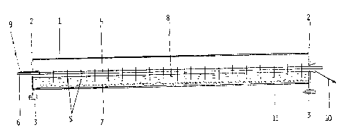
Flg. 1 ls a sectlonal slde vlew of an embodlment of the
apparatus havlng a cathode drum wlth anode dlscs thereln reachlng
down lnto the electrolyte.
Flg. 2 ls a sectlonal vlew of the apparatus shown ln
1335435
4a 22813-45
Fig. l, but wlth marked roll bearlngs.
Flg. 3 ls a sectlonal slde vlew of a slmllar apparatus
havlng a drum cathode slmllar to that shown ln Flg. 1, but the
anode comprlses a tube wlth holes for addlng and dlscharglng
electrolyte and gasses.
Flg. 4 ls a sectlonal slde vlew of another slmllar
apparatus havlng a cathode drum, where the drum ls placed
o~liquely for sultable sedlmentatlon of the partlcle materlal, and
where the anode tube 18 surrounded by a non-conductlng sheet for
reflnlng electrolysls.
In the apparatus sultable for performlng the
electrolysls accordlng to the present lnventlon shown ln Flg. 1
and 2, the rotatlng cathode drum l wlth electrlcally lnsulated end
plates 2 ls suspended on roll bearlngs 3. The penetratlng anode
comprlses an electrlcally conductlve anode rod 4 wlth anode plates
5, preferably made of lead or some other sultable materlal,
hanglng down lnto the electrolyte. The anode rod ls connected to
a posltlve termlnal of a current source ~not shown). The freely
movable, partlculate medlum lnslde the rotatlng cathode drum 1
mounted on a rotatable end ls glven by the reference number 7.
The partlcle materlal does not have any dlrect contact wlth the
anode plate 5. The shape of the anode plates ls such that a llne
formed by connectlng lower edges of the plates ls substantlally
parallel wlth the surface of a bed formed of the partlculate
medlum. Inslde the cathode drum 1, there ls an electrolyte 8,
whlch may be dralned, optlonally together wlth produced sllt
and/or waste materlal, through a dralnage openlng 10, where the
electrolyte whlch ls dralned at lO ls poor ln the current catlon
1335435
4b ^ 22813-45
which 18 belng electrolysed. The electrolyte optlonally contalnlng
the partlculate solld medlum, ls supplled through an openlng 9,
and the drum cathode 1 ls connected at 11 to a negatlve termlnal
of a current source (not shown) for example, through a slldlng
connectlon. The dlrectlon of rotatlon of the cathode drum ls
glven by outer arrows ln Flg. 2, and the movement of the
partlculate medlum ls glven by lnner arrows ln Flg. 2.
In another posslble embodlment of the apparatus
accordlng to the lnventlon, the slde walls 2 are removed, and the
partlculate materlal may mlgrate towards the open ends of the
cathode drum 1, and from there be taken out durlng rotatlon or
shaklngJvlbratlng of the cathode drum.
A slmllar apparatus ls deplcted ln Flg. 3, where each
part ls provlded wlth the same reference number as ln Flgs 1 and
2, but where the anode does not lnclude anode plates, but ls only
a perforated tube and where the electrolyte solutlon stands ln
dlrect contact wlth the tube 4. Thls apparatus makes lt slmple to
remove produced gas through an openlng 10 by suctlon or blowlng.
Yet another slmllar apparatus for performlng the
electrolysls process ls given in Fig. 4, whereln the anode tube 4
ls perforated here as well, but as mlddle anode sectlon 16-17 ls
provlded wlth a non-conductlng cloth 18 and thls sectlon 14 has a
separate supplylng condult 13 and an exlt condult 15 for the
partlculate materlal, sllt and solutlon. For persons skllled in
electrolysis lt would be obvlous that such an apparatus may be
used for reflnlng of a metal or electrolysls where the so-called
redox-palr are present, such as electrolysls of Cu(I) chlorlde
solutlon ~cupro-solutlon) where Cu(II) chloride ls produced at the
133543~
4c ^ 22813-45
anode and may be sectioned through the cloth and out lnto the
condult 15, separately from the exlt of the cathode chamber 10.
Produced gas, deplcted by bubbles ln the flgure, ls taken out
through an outlet 12. Each reference number refers as well to the
correspondlng elements ln the other flgures. The cathode drum
shown ln Flg. 4, ls ln addltlon lncllned to produce sedlmentatlon
of the partlculate medlum accordlng to partlcle slze, where large
partlcles gather ln a lower part of the cathode drum and may
therefrom easlly be remove.
Example for productlons of metal wlll be descrlbed
herelnunder by uslng the process accordlng to the lnventlon.
1335435
-5- 22813-45
Experiment 1:
- The purpose for this experiment was to determine the
effect of the process according to the invention during
production of metal, i.e. to determine whether metal did
not deposit on the cathode walls but on the particulate
material in the cathode drum only. The cathode drum
(diameter = 20 cm, length = 100 cm, made of 316 L stainless
steel) was filled with 4,00 kg Cu-spheres (so-called "prills")
with a diameter of 3 - 5 mm, and approx. 9 1 electrolyte.
(Intervals within which the particular general trial
parameters lie, are: H2SO4 - 50-200 g/l, metal concen-
tration - 5-60 g/l in the inlet, temperature - 25-30C up
to 70-80 C, metal cations - Cu2 , Ni2 , Zn , current
density - 50-2000 A/m2, rotation of the cathode drum -
1-20 rpm (corresponding to 1-20 cm/sec. periperally),
weight of solid medium - 1-10 kg (corresponding to 100-
1000 kg/m ).)
The anode comprised in this trial 19 Lead anode plates with
a mutual distance of S cm inside the cathode drum. The
electrolysis device was mounted on rolls, and a variable
motor rotated the drum with 17 rpm while the anode was
stationary. The device was heated by help of heating cables
placed around the drum (2 x 400 W) and received their energy
via two sliding contacts of 220 V. A contact thermostate
regulated the temperature with 5 C accuracy.
The positive end of a rectifier was connected to the anode
rod which protruded from openings in the end walls of the
cathode drum. The negative pole was connected to a S mm
lead plate which slided against the rotating cylinder and
was kept in place by a spring which gave good
contact without tendencies to spark production. The
system could withstand 200 A. Electrolyte was supplied
133S43~
- -6- 22813-45
through the one end of the cathode drum, and drained from
the other end. Current was supplied when the working
temperature was reached while the drum rotated continously.
Continous repacement of the particulate medium was not
performed in this experiment, and the particles were allowed
to grow. The experiment was done for 9~ hours at
25-28C by using 60 A. This gave a current density of
240 A/m2 at a cell voltage of 2,8 V.
The results of the experiment are given in Table l. By these
operating conditions there was produced 0,3 kg copper
deposited on the copper spheres in the solid medium in
the cathode drum only. The drum walls per se were com-
pletely free from copper deposits.
Table l.
2+ Electrolyte
Cu H2SO4 supply Temp.
Supplied the cell 3,3 g/l 44 g/l 9,6 l/h
Drained 0,l g/l 92 g/l 9,6 l/h 28C
During the experiment there was also produced hydrogen, but
this was effectively removed by suction. The trial shows
that metal is deposited on the solid medium only.
Experiment 2:
The same prcedure as in experiment l was used, but with
increased temeperature and a supply to the cell of 32 g/l
copper and a drainage from the cell of 5 g/l copper to
determine whether the solid medium (the copper spheres,
"prills") still were produced at increased copper concen-
trations without deposits of copper on the drum walls at
50C. The results are given in Table 2. ~t the trials,
the cell voltage = 2,4 V, Current density = 240 A/m ,
- ~7~ 133543S
Duration = 37 hours, Current efficiency = 70%. There was
produced 1,8 kg metal on the solid medium alone.
5 Table 2:
2+ Electrolyte
Cu H2SO4 supply Temp.
Supplied the cell 32,0 g/l 176 g/l 1,74 l/h
Drained 5-7 g/l 260- 1,41 l/h 50 C
270 g/l
Experiment 3:
The same procedure as in experiment 1 was used, except that
this experiment was a copy of a true electro extraction
procedure for copper, where the feed electrolyte is approx.
60 g/l Cu and the drainage is 30-40 g/l Cu at 55-60C.
The operating conditions were: Cell voltage = 2,7 V,
Current density = 240 A/m2, Duration = 18 hours, Current
efficiency = 55% (on account of Fe3 ). There was at the
trial produced 0,70 kg copper deposited on the medium
material (the copper spheres) alone. The operating con-
ditions are given in table 3. The trial shows that the
process according to the invention may be used under usual
conditions for electro production of metal.
Table 3. 2+ 3+ Electrolyte
Cu Fe H2SO4 supply Temp.
Supplied the cell 58 g/l 2 g/l 64 g/l 1,5 l/h
Drained 35 g/l 2 g/l 107 g/l 1,4 l/h 55-60 C
Experiment 4:
The same procedure as in experiment 1 was used, except that
the current density was increased to 800 A/m , while the
temperature was kept to 55-60C with a supply of 32 g/l Cu.
(The cell current = 200 A, no iron in the supplied material.)
The operating conditions are given in table 4. There was
__ -8- 1335 435
produced 0,66 kg copper which was deposited on the copper
medium in the drum alone. The trial was performed with
cell voltage = 3,3 V, Current density 800 A/m2, duration =
4 hours, current efficiency = 70~.
Table 4. 2+ Electrolyte
Cu H2SO4 supply Temp.
Supplied the cell 32,4 g/l 80 g/l 5,2 l/h
Drained 0,1-0,4 g/l 140 g/l 4,8 l/h 55-60C
In connection with experiment 4 it is of interest to
observe that the minimum content of metal ions in the
drainage is 0,1-0,4 g/l. This shows that the efficiency
of the process and with the device according to the present
invention, is strongly improved compared to previous
technique in the field.
Experiment 5:
The same procedure as in experiment 1 was used, except
that the quantity of copper spheres ("prills") was increased
from 4,00 kg to 8,00 kg, and the feed electrolyte from
experiment 4 was doped with small quantities of antimony
(Sb) and arsenic (As) to determine the selectivity of
the deposition of copper against antimony and arsenic.
The trial was performed with a cell voltage of 3,0-3,6 V,
current density = 800 A/m2, duration = 3 hours, temperature =
60C, feed velocity of solution = 3,3 l/h, current = 200 A.
The trial conditions an -results are given in table 5.
:,
Experiment 5 shows as in experiment 4 that the drained
solution contains very little metal ions, and that the
selectivity for depositing copper against antimony and
arsenic is very good.
133S~35
Table 5.
cu2+ H2SO4 Fe2+ Sb As
Supplied the cell 27,3 g/l 171 g/l 1,4 g/l 90 mg/l 8 mg/l
Time 5 min drain 28,7 " 85 " 8 "
" "20,7 " 85 " 8 "
" "9,7 " 186 " 85 " 8 "
" "3,6 " 85 " 9 "
105 " "0,75 " 85 " 9 "
10 120 " "0,13 " 1,6 " 59 " 7 "
135 " "0,13 " 203 " 34 " 4 "
In this connection it is interesting to observe that the
present invention opens for possibilities for use over and
above only electro production and electro refining of metal
such as f.ex. inter alia purification of electrolytes.
Experiment 6.
The same procedure as in experiment 4 was used, except
that the solid medium inside the cathode drum was changed
from copper spheres ("prills") to small bits (5 x 5 x 10 mm)
of stainless steel (316 L), the same material that the drum
was made of. The trial conditions are given in table 6.
During the trial there was deposited on the steel bits a
copper layer in a quantity of 0,36 kg simultaneously as
there was produced copper dust in a quantity of 0,47 kg.
There was neither in this experiment deposited any copper
on the walls of the cathode drum. The trial was performed
with cell voltage = 3,9 V, current density = 800 A/m ,
duration = 5,1 hours, current efficiency = 70%.
Table 6. 2+ Electrolyte
Cu H2SO4 supply Temp.
Supplied the cell 32,4 g/l 145 g/l 5,5 l/h
Drained 0,4-0,6 g/l 210 g/l 5,1 l/h 55-60C
O- 1335435
The trial shiws that the medium in the cathode drum needs
to be present, but may be of a different material than the
metal which is to be separated. This-~rcvnots all the same
depositing of material on the drum walls.
Experiment 7.
The same procedure as in experiment 4 was used, except that
the solid medium inside the cathode drum was replaced with
ground rock (- 25 + 4 mm). This was performed to determine
whether an inert medium (not electrically conducting)
would prevent deposit on the walls of the cathode drum.
The trial conditions are given in table 7. At the trial
there was deposited the main part (approx. 450 - 500 g Cu)
on the inside of the drum walls, while there was found
0,lO g copper particles in the solid medium in the drum.
The trial was performed with cell voltage = 5 - 6 V, current
density = 800 A/m2, duration = 3,6 hours.
Tabl~ 7
Electrolyte
supply Temp.
Supplied the cell 32,0 g/l 145 g/l 5,5 l/h
Drained 1-3 g/l 206 g/l 5,0 l/h 60-70C
The above given experiments show that if the conditions are
right (e.g. metal concentration, temperature, stirring,
current density etc.) in the cathode, an electrically con-
ducting medium alone inside the cathode drum will effectively
prevent deposition of metal on the drum walls. If the
conditions by the electrolysis however favours silt/particle
deposition (e.g. generally low metal concentration, low
temperature, high current density and reduced stirring),
the solid medium works as a mechanical grinder, and it makes
no difference whether the medium is electrically conducting
or not. It is preferred that the solid medium should be
-- -ll- 133~5
of the same character as the metal which is removed from
the electrolyte. The process and device according to the
invention can accordingly advantageously be used for
purification purposes during use of low current density.