Note: Descriptions are shown in the official language in which they were submitted.
~ J ~ ~ B61816544
~ ~ 13369~2
A GUIDE ROLL APPARATUS FOR A
DRYER OF A PAPER MACHINE DRYING SECTION
BACKGROUND OF THE INVENTION
FIELD OF THE INVENTION
This invention relates to a guide roll apparatus for
a dryer of a paper machine drying section. More
specifically, this invention relates to a guide roll
apparatus in which the web and a web-supporting felt
disposed contiguous relative to each other are guided
through the drying section of a papermaking machine.
INFORMATION DISCLOSURE STATEMENT
For many years, so-called "serpentine run" or
"uno-run n drying sections have been employed by
papermakers in order to dry the formed web emerging from a
press section of the papermaking machine. Such serpentine
type drying sections typically included an upper and a
lower line of dryer drums and the web to be dried would
successively move supported by a felt between alternate
upper and lower dryer drums. Although the aforementioned
serpentine run has been extensively employed, such
arrangement has certain inherent disadvantages. For
example, when both the upper and lower line of dryer drums
are heated, the web comes into physical contact only with
the heated dryer drums of the upper line of dryers because
only the felt comes into direct contact with each of the
dryer drums of the lower line. In operation of such
serpentine drying sections, the application of heat to the
lower line of dryers has, to a large extent, been
ineffective due the heat-insulating effect of the drying
felt disposed between the surface of each lower drying
drum and the supported web. In view of the resultant
; B61816544
~ 1336~2`
wastage of heating steam and the relatively costly
requirement for such lower line of dryer drums, such lower
line of drums have recently been replaced by guide rolls
(or transfer rolls) disposed between each adjacent upper
dryer drum. Throughout this specification, the term
"guide roll" is intended to include transfer rolls for
transferring the web between adjacent dryers or grooved
vacuum rolls. This so-called "Bel Run" arrangement with
guide rolls disposed between adjacent upper drying drums,
has `reduced the steam requirements compared with the
aforementioned serpentine run arrangement. Also, such
guide rolls are smaller and generally less costly than the
corresponding lower dryer drums. Furthermore, due to the
smaller size of the guide rolls, the draw, or length of
the felt, between an upper dryer drum and a respective
guide roll is considerably reduced compared with the
serpentine run thereby avoiding, to a large degree,
problems arising from the edges of the web fluttering when
operating at high production rates of 3,000 fpm or more.
Another advantage of the Bel Run system is that the
overall height of the Bel Run is less than the height of a
serpentine run.
With the ever-increasing production speeds of
papermaking machines, however, it is not uncommon to
operate dryer sections of the Bel Run type in excess of
4,000 fpm. At such speeds, even with the relatively short
draw between the guide roll and associated dryer drum,
there exists a tendency for the edges of the web to lift
and flutter relative to the supporting felt as the
contiguous felt and web extend around and wrap a portion
of the guide roll.
13 3 6 9 l 2
--3-- .
In the prior art, various types of vacuum rolls have
been employed in an attempt to adequately draw the web,
and particularly the web edges, into close conformity with
the supporting felt. However, such vacuum rolls are
relatively costly to manufacture, such cost approaching
the cost of the manufacture of a corresponding lower dryer
drum of a serpentine run system.
The present invention provides a greatly simplified
type of guide roll which avoids the complex structure of
the~aforementioned vacuum rolls used previously.
The present invention, essentially, includes a guide
roll having a plurality of spaced, circumferential grooves
defined by the external surface of the guide roll such
that as the felt and web wrap around the guide roll, the
buildup of air pressure at the ingoing nip defined by the
felt and the guide roll, is dissipated through the
plurality of channels, or grooves.
More specifically, the present invention includes a
guide roll in which the edge portions of the guide roll
have a plurality of spaced, circumferential grooves in
combination with a vacuum hood, or vacuum inducing device,
disposed in the pocket formed by the ingoing and outgoing
felt and the guide roll such that the buildup of pressure
at the ingoing nip is drawn away from this nip through the
grooves towards the vacuum hood.
Alternately, the present invention accomplishes the
same purpose by providing a hollow guide roll defining a
plurality of radially-extending holes disposed adjacent to
the respective edge portions of the roll. A partial
vacuum is applied to the hollow roll through one or more
journals of the roll such that in use, the air pressure
built up between the felt and the edge portions of the
s61816544
1336942
roll is drawn away through the holes towards the vacuum,
and additionally, vacuum support is provided directly to
the web edges as they wrap around the guide roll.
Therefore, it is a primary object of the present
invention to overcome the aforementioned complexity and
cost factors involved with the prior art guide rolls and
to provide a guide roll apparatus that offers a
significant contribution to the art of drying paper webs
in a papermaking machine.
r Another object of the present invention is the
provision of a guide roll apparatus in which a first and
second edge portion of a guide roll defines a plurality of
spaced, circumferential grooves such that in use of the
apparatus, the buildup of pressure at the ingoing nip is
dissipated through the grooves towards a vacuum hood
disposed within a pocket defined by the ingoing and
outgoing felt and the guide roll.
Another object of the present invention is the
provision of a guide roll apparatus which includes a
hollow guide roll having radial holes disposed adjacent
the respective side edges of the roll. Vacuum is applied
through the hollow guide roll such that in use, the
buildup of air pressure between the felt and particularly
the edge portions of the guide roll is dissipated through
the holes towards the vacuum.
Another object of the present invention is the
provision of a guide roll in which the hollow guide roll
includes a divider plate for dividing an enclosure of the
hollow guide roll into a first and second enclosure with
the first and second enclosure being, respectively, in
communication with the holes of the first and second edge
portions.
B61816544
-~- 1336g~
. ~ .
Another object of the present invention is the
provision of a guide roll apparatus in which the divider
plate defines a restrictor opening such that a greater
vacuum is applied to one edge portion than to the other
edge portion. This greater vacuum is used when threading
a tail of a web so that loss of vacuum through the
remaining unwrapped edge portion is inhibited.
Other objects and advantages of the present invention
will be readily apparent to those skilled in the art by a
consideration of the following detailed description of the
preferred embodiment of the present invention taken in
conjunction with the annexed drawings.
SUMMARY OF TH E I NVENT I ON
The present invention relates to a guide roll
apparatus which is disposed adjacent to a dryer of a paper
machine drying section. More particularly, the invention
relates to a guide roll apparatus which guides a
contiguous web and web-supporting felt through the drying
section. The apparatus includes a rotatable guide roll
having an outer cylindrical surface which defines a first
and a second edge portion. The cylindrical surface also
defines a central portion which is disposed between the
edge portions. The first edge portion defines a first
plurality of air flow channels such that in use of the
apparatus, when the web and felt are guided around the
rotatable guide roll, air entrapped between the first edge
portion and the felt wrapped around the first edge
portion, is permitted to flow through the first plurality
of channels away from the felt so that fluttering of the
web during guidance around the first edge portion is
inhibited. Similarly, the second edge portion also
defines a second plurality of air flow channels such that
~ B61816544
13369~2
_ ,9
in use of the apparatus, when the web and felt are guided
around the rotatable guide roll, air entrapped between the
second edge portion and the felt wrapped around the second
edge portion is permitted to flow through the second
plurality of channels away from the felt so that
fluttering of the web during guidance around the second
edge portion is inhibited.
In one particular embodiment of the present
invention, the first and the second plurality of air flow
channels are, respectively, a first and a second plurality
of spaced, circumferential grooves. Furthermore, the
central portion may also define a third plurality of
spaced, circumferential grooves for inhibiting a buildup
of air pressure between the central portion and the felt
thereby inhibiting detachment of the web relative to the
felt during guidance of the web around the guide roll. A
vacuum means is disposed adjacent to the guide roll within
the pocket defined by the ingoing and outgoing felt and
the guide roll. This vacuum means enhances the flow of
air through the first and second plurality of grooves.
The vacuum means includes a hood which is disposed within
the pocket. The hood is sealed by means of seal means
disposed between the hood and the guide roll, or felt, for
sealing the hood relative to the guide roll. The seal
means can be mechanical seals or air jet seals. The hood
is connected to a source of partial vacuum or a source of
pressure which can be used to induce a vacuum such that in
use of the apparatus, air entrapped between the felt and
the wrapped portion of the edge portions is drawn through
the first and second plurality of channels and through the
hood thereby inhibiting fluttering of the respective edges
of the web.
l~ B61816544
1336942
~,
In an alternative embodiment of the present
invention, the guide roll includes an enclosure means
defined by the guide roll. The first and second plurality
of air flow channels are, respectively, a first and second
plurality of holes extending between the enclosure means
and the cylindrical surface of the guide roll such that
air flows through the holes from the cylindrical surface
towards the enclosure. More particularly, the guide roll
also includes a first and second journal bearing disposed
respectively adjacent to the first and second edge
portions of the guide roll for rotatably supporting the
guide roll. A first and second journal are rigidly
connected to the respective first and second edge
portions. These first and second journals are rotatably
supported by, respectively, the first and second journal
bearings. The first and second journals respectively
define first and second bores. The guide roll apparatus
also includes a vacuum means which is disposed adjacent to
the guide roll for enhancing the flow of air through the
first and second plurality of holes and through the
enclosure means which is in fluid communication with,
respectively, the first and second bores. The vacuum
means is connected, respectively, to the first and second
bores to assist air flow.
The guide roll also includes a divider plate means
which is disposed within the enclosure means between the
first and second edge portions for dividing the enclosure
means into a first and a second enclosure. This
arrangement is such that the first and second enclosures
are in fluid communication respectively with the first and
second bores.
~ s61816544
-8- 133694Z`
In a further modification, in order to assist the
threading of a tail of the web, the divider plate defines
a restrictor opening. The vacuum means is disposed
adjacent to the guide roll and in fluid communication with
one of the enclosures such that in use of the apparatus
when threading the tail of the web, a greater vacuum is
applied to the enclosure which is adjacent to the tail,
this greater vacuum being due to the restrictor opening.
By this means, the loss of vacuum to that edge portion
that is unwrapped by the web is avoided.
Although the present invention is described
hereinafter with reference to a preferred and alternative
embodiments, it will be evident to those skilled in the
art that many variations and modifications of the basic
concept of the present invention can be carried out
without departing from the spirit and scope of the
invention as defined by the appended claims. Such
modifications include helically-grooved guide rolls, edge
portions having blind holes drilled therein, lateral
grooves and the like.
BRIEF DESCRIPTION OF THE DRAWINGS
Figure l is a side-elevational view of a prior art
serpentine type dryer section showing an upper and a lower
line of dryer drums with the web tending to detach from
the supporting felt during guidance of the same around a
lower dryer drum.
Figure 2 shows a typical Bel Run system in which the
lower dryer drums are replaced by smaller vacuum rolls.
Figure 3 is a side-elevational view of a Bel Run
drying section according to the present invention in which
the plurality of pocket ventilation rolls are replaced by
guide rolls having spaced, circumferential grooves and
~ B61816544
q 13369~2
vacuum hoods disposed within the respective pockets near
the edges.
Figure 4 is an enlarged, perspective view of one of
the guide rolls of the embodiment shown in figure 3
showing a first and second edge portion of the guide roll
having spaced, circumferential grooves. This roll also
includes a central portion which is grooved.
Figure 5 is an enlarged, sectional view taken on the
line 5-5 of figure 3 showing the vacuum means disposed
adjacent to the edge portions of the guide roll.
Figure 6 is a sectional view taken on the line 6-6 of
figure 5 showing how the buildup of air pressure at the
ingoing nip is dissipated through the circumferential
grooves and vacuum hood.
Figure 7 is a perspective view of a guide roll
according to an alternative embodiment of the present
invention showing the central portion being grooved and
the first and second edge portions defining a plurality of
holes.
Figure 8 is a sectional view taken on the line 8-8 of
figure 7 and shows the journal bearings and the connection
of the journals to a source of partial vacuum.
Figure 9 is a similar view to that shown in figure 8
but shows an alternative embodiment of the present
invention in which the divider plate defines a restrictor
opening such that in use of the apparatus of figure 9,
when vacuum is applied, a greater vacuum is applied to one
edge portion than the other due to the restrictor opening
thereby assisting threading of a tail of the web, and
Figure 10 is a sectional view showing an alternative
embodiment of the present invention in which the vacuum
~ B61816544
~ 1336942
box is replaced by a blow box which induces a vacuum by
the Coanda effect.
Similar reference characters refer to similar parts
throughout the various embodiments of the present
invention.
DETAILED DESCRIPTION OF THE DRAWINGS
Figure 1 is a side-elevational view of a prior art
type serpentine run, or Uno-Run dryer section generally
designated 10. The web W is wrapped by the felt F around
a first dryer drum 12 of an upper line of dryer drums
generally designated 14. The web W and felt F leave the
heated upper dryer drum 12 and extend in open draw towards
and around a lower dryer drum 16 of a lower line of dryer
drums generally designated 18. The lower dryer drum 16 is
heated but the felt F is disposed between the heated
surface 20 of the dryer drum 16 and the web W so that the
drying effect of the dryer drum 16 is reduced.
Furthermore, due to the pumping effect of the wedge of air
A at the ingoing nip N defined by the felt F and the
surface 20 of the dryer drum 16, there exists a tendency
of the web W to detach from the felt F as shown in figure
1.
Figure 2 is a side-elevational view of a typical
prior art Bel Run type dryer section 10A including a dryer
drum 12A and a vacuum guide (or transfer) roll 16A
disposed between the dryer drum 12A and an adjacent dryer
drum 13. AS will be seen, the Bel Run system has an
advantage over the serpentine run system of figure 1 in
that the provision of a costly line of lower dryer drums
is replaced by smaller vacuum rolls such as 16A.
Furthermore, the open draw distance between the dryer drum
12A and the vacuum roll 16A is less than the distance
B61816544
~.
1336942
between the dryer drum 12 and the dryer drum 16 of figure
1.
However, pocket ventilation roll 16A of the type
shown in figure 2, are relatively complex and require the
provision of a plurality of radial drillings along the
entire outer surface 20A thereof. Additionally, such
pocket ventilation roll 16A must be hollow and include
internal partitions with relatively complex sealing means
between such partitions and the inner cylindrical surface
of the guide roll 16A. In practice, it has been estimated
that, on the average, 65 man-hours are required on the
drilling operation alone in order to produce a single
vacuum roll. Due to the complexity, vacuum rolls,
although smaller than the corresponding lower dryer drums
of the serpentine system, are comparable in cost. Thus,
the only savings are in the reduction in steam
requirements, the reduction in dryer section length and
the improvement in runnability.
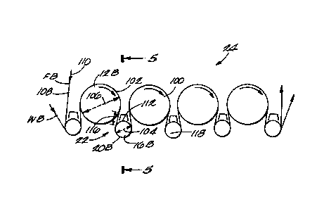
Figure 3 is a side-elevational view of the present
invention in which the relatively complex vacuum roll such
as 16A is replaced by a solid roll 16B having spaced,
circumferential grooves defined by the outer surface
thereof.
Figure 4 is an enlarged perspective view of the guide
roll 16B. The guide roll apparatus generally designated
22 shown in figures 3 and 4 is disposed adjacent to a
dryer 12B of a paper machine drying section generally
designated 24. The apparatus 22 guides a contiguous web
WB and a web-supporting felt FB through the drying section
24. The apparatus 22 includes the rotatable guide roll
16B having an outer cylindrical surface 20s as shown in
figure 4. The surface 20B defines a first and second edge
- B61816544
--lL 1 3 3 6 9 ~ 2
portion 26 and 28 respectively and a central portion 30
disposed between the edge portions 26 and 28. The first
edge portion 26 defines a plurality of air flow channels
31,32,33,34 and 35 such that in use of the apparatus, when
the web WB and the felt FB are guided around the rotatable
guide roll 16B, air entrapped between the first edge
portion and the felt wrapped around the first edge
portion 26 is permitted to flow through the first
plurality of channels 31-35 away from the felt FB so that
separation of the web WB from the felt FB and the
associated fluttering of the web WB during guidance around
the first edge portion 26 iS inhibited. Similarly, as
shown in figure 4, the second edge portion 28 defines a
second plurality of air flow channels 36,37,38, 39 and 40
such that, in use of the apparatus when the web WB and
felt FB are guided around the rotatable guide roll 16B,
air entrapped between the second edge portion 28 and the
felt FB wrapped around the second edge portion 28 iS
permitted to flow through the second plurality of channels
36-40 away from the felt FB so that fluttering of the web
WB and separation of the web during guidance around the
second edge portion 28 iS inhibited. As shown in figure
4, the first and second plurality of air flow channels
31-35 and 36-40 respectively, are a first and a second
plurality of spaced, circumferential grooves.
As shown in figure 4, the central portion 30 also
defines a third plurality of spaced, circumferential
grooves 41,42,43,44,45,46 and 47 for inhibiting a buildup
of air pressure between the central portion 30 and the
felt FB thereby inhibiting detachment of the web WB
relative to the felt Fs during guidance of the web WB
around the guide roll 16B.
` B61816544
133~942
_ -~3 ~ ~
As shown particularly in figure 5, which is an
enlarged fragmentary, cross-sectional view taken on the
line 5-5 of figure 3, the guide roll apparatus 22 also
includes vacuum means generally designated 48 which is
disposed adjacent to the guide roll 16B for enhancing the
flow of air from the first and second plurality of
channels 31-35 and 36-40 respectively. More particularly,
figure 6, which is a sectional view taken on the line 6-6
of figure 5, shows one such vacuum means 48. The vacuum
means 48 includes a hood 50 which is disposed within a
pocket 52 defined by the guide roll 16B and an ingoing and
outgoing side 54 and 56 respectively of the web WB and
felt FB. Seal means 58 and 60, disposed between the hood
50 and the outer surface 20B of the guide roll 16B, or the
felt, seal the hood 50 relative to the guide roll 16B.
The hood 50 is connected to a source of partial vacuum V
by ducting 62 as shown in figure 5 so that in use of the
apparatus 22 the air entrapped between the felt FB and the
wrapped portion of the edge portions 26 and 28
respectively, is drawn from the first and second plurality
of channels 31-35 and 36-40 and through the hood 50
thereby inhibiting fluttering of the respective edges of
the web WB.
Alternatively, the vacuum hood could use air pressure
and the Coanda effect to induce a vacuum between the hood
and the adjacent roll or felt surfaces.
Figure 7 is an enlarged, perspective view of an
alternative guide roll 16C according to the present
invention. As shown in figure 7, the first and second
plurality of air flow channels are, respectively, a first
and second plurality of holes 31C,32C,33C,34C and 35C and
36C,37C,38C,39C and 40C. The holes 31C-35C and 36C-40C
~ B61816544
~ ~Li~ 13363~2
are defined by the.outer cylindrical surface 20C of the
guide roll 16C.
Figure 8 is a sectional view taken on the line 8-8 of
figure 7, but also shows the hollow construction of the
guide roll 16C and its connection to a vacuum means 48C.
As shown in figure 8, the holes 31C to 35C are radially
drilled relative to the outer surface 20C of the guide
roll 16C. As shown in figures 7 and 8, the guide roll 16C
also includes an enclosure means generally designated 64C
defined by the guide roll 16C. Each hole of the first and
second plurality of holes 31C-35C and 36C-40C extends from
the enclosure means 64C to the cylindrical surface 20C
such that in use of the apparatus 22C air flows through
the holes 31C-35C and 36C-40C from the cylindrical surface
20C towards the enclosure 64C as shown by the arrows 65,66
and 67. More specifically, as shown in figure 8, the
guide roll 16C includes a first and second journal bearing
68 and 70 disposed respectively adjacent to the first and
second edge portions 26C and 28C of the guide roll 16C for
rotatably supporting the guide roll 16C. A first and
second journal 72 and 74 are rigidly connected to,
respectively, the first and second edge portions 26C and
28C. The journals 72 and 74 are rotatably supported by
the first and second journal bearings 68 and 70 with the
first and second journals 72 and 74 defining respectively,
first and second bores 76 and 78. The guide roll
apparatus 22C includes vacuum means generally designated
48C disposed adjacent to the guide roll 16C for enhancing
the flow of air through the first and second plurality of
holes 31C-35C and 36C-40C and through the enclosure means
64C which is in fluid communication with respectively the
first and second bores 76 and 78. The vacuum means such
- B61816544
-15- 1336942
as a blower fan 48C is connected to, respectively, the
first and second bores 76 and 78. A divider plate means
80 as shown in figure 8, iS disposed within the enclosure
means 64C between the first and second edge portions 26C
and 28C. The plate 80 divides the enclosure means 64C
into a first and second enclosure 82 and 84 respectively
so that the first and second enclosures 82 and 84 are in
fluid communication with the first and second bores 72 and
74.
Eigure 9 is a similar view to that shown in figure 8
but shows a further modification in that the divider plate
80D which is disposed within the enclosure means 64D
between the first and second portions 26D and 28D divides
the enclosure means 64D into a first and second enclosure
82D and 84D respectively but the divider plate 80D defines
a restrictor opening 86. A vacuum means such as a blower
fan 48D iS disposed adjacent to the guide roll 16D and in
fluid communication with the enclosure 82D and enclosure
84D such that in use of the apparatus 22D, when threading
a tail T of the web, a greater vacuum is applied to the
enclosure 82D which is adjacent to the tail T due to the
restrictor opening 86 and closed isolation damper V
thereby avoiding the loss of vacuum through the edge
portion 28D which is unwrapped by the web WD. The chamber
84D iS connected to the vacuum means 48D through bore 78.
Additionally, the isolation damper V as shown in figures 8
and 9 has the advantage of providing less pressure drop in
the exhaust.
Figure 10 shows an alternative embodiment of the
present invention, however, the vacuum means 48 shown in
figure 5 is replaced by a blow box 48E having a plurality
of slots 88,89 such that when the box 48E iS pressurized,
- ~- B61816544
1 3 3 6 9 4 2
air flowing out through the slots 88,89 induces a partial
vacuum in the vicinity of the grooves 31E,32E,33E and 34E.
In operation of the apparatus according to figures
3-6, the web supported by the felt is guided around the
guide roll 16B with the felt FB being disposed between the
outer surface 20B of the guide roll 16B and the web WB.
When the apparatus 22 is rotating at high speed, a wedge
of air builds up at the ingoing nip NB defined by the felt
FB and the outer surface 20B of the guide roll 16B as
shown in figure 6. This buildup of air pressure tends to
cause a pumping action through the permeable felt FB and
results in a possible detachment of the web WB from the
felt FB. The present invention overcomes this problem by
the provision of a plurality of circumferential grooves
disposed in a cross-machine direction along the respective
edge portions 26 and 28 of the guide roll 16B. The air
that would become entrapped if the outer surface were
plain, is channeled, according to the present invention,
through the annular grooves such that the air can flow
around the grooves and out into the pocket 52.
Preferably, as shown in figures 5 and 6, a vacuum hood 50
is provided within the pocket 52 to assist in the flow of
air from the ingoing nip NB through the grooves and into
the hood 50.
In operation of the alternative embodiment of the
present invention, as shown in figures 7 and 8, instead of
providing a vacuum hood, the guide roll 16C defines a
hollow enclosure and a partial vacuum is applied to both
hollow journals of the guide roll 16C. Radial holes
31C-35C and 36C-40C are drilled in the vicinity of the
edge portions 26C and 28C such that the buildup of air
pressure between the felt and the outer surface of the
~ ~ B61816544
13369~2
edge portions is dissipated through the holes into the
enclosure means 64C towards the vacuum means 48C.
Another embodiment of the present invention includes
a divider plate 80D defining a restrictor opening 86.
Vacuum means are applied to one journal 72D during
threading such that a greater vacuum exists in enclosure
82D than in enclosure 84D. The greater vacuum existing in
enclosure 82D is particularly useful in enabling an
operator to thread a narrow tail T through the dryer
section. Usually, the tail T is approximately 2 inches in
width The width of the edge portions 26D and 28D is
large enough to insure the tail is always covered. If no
divider plate were employed, then an equal vacuum would be
applied through the holes of the edge portions 26D and 28D
respectively. Because no web is present adjacent to the
edge portion 28D but only a tail T adjacent the edge
portion 26D, much of the vacuum applied would be lost
through the holes of the edge portion 28D as there would
be little resistance to air flow through the unwrapped
felt FD adjacent edge portion 28D. Due to the restrictor
opening 86 of the present invention, the majority of the
vacuum is applied through the edge portion 26D adjacent to
the tail T of the web When the web WD has been threaded,
air flow through the holes 36D-40D will be greatly reduced
due to the presence of the web. Additionally, the
isolation damper, if used, would be opened. Therefore,
the effect of the restrictor opening will be minimal with
approximately the same vacuum being applied to both edge
portions 26D and 28D. Although circumferential grooves of
annular configuration have been described, it will be
appreciated by those skilled in the art that helical
- , B61816544
133~942
grooves could be used and these are included within the
scope of the invention.
The present invention provides an economical guide
roll for use in particularly a Bel Run system although
such guide roll can be used in many types of web guiding
systems. Not only does the present invention provide a
guide roll of simple construction requiring minimum
machining, but also it provides a simple means for
enabling threading of a tail through a drying section.