Note: Descriptions are shown in the official language in which they were submitted.
~ 3371 6~
. . .
CHEMICAL VAPOR DEPOSITION OF TIN OXIDE
ON FLOAT GLASS IN THE TIN BATH
Background of the Invention
The present invention relates generally to the art of
producing infrared-reflecting coated glass products, and more
particularly to non-iridescent. high transmittance, low emissivity,
infrared-reflecting coated glass products.
Transparent infrared-reflecting films such as tin oxide may
be deposited on a substrate such as glass by a variety of methods,
including the application of thermally decomposable compounds to a
heated surface. Useful methods for forming transparent infrared
reflecting tin oxide films are taught in U.S. Patent No. 3,107,177 to
Saunders et al, U.S. Patent No. 3,677,814 to Gillery, and U.S. Patent
No. 4,263,335 to Wagner et al.
Tin oxide films are especially effective infrared reflectors
at thicknesses of about 1000 to 8000 Angstroms. However, if the
thickness is not sufficiently uniform, the films tend to display a
multiplicity of interference color effects commonly referred to as
iridescence. Such interference effects render the coated glass
20 aesthetically unacceptable for most architectural applications.
Iridescence is not observed in thinner films, however, these films
have insufficient infrared reflectance to be practically useful.
Likewise, iridescence is not observed in thicker films; however, these
films tend to be hazy, have relatively low transmittance, and are
25 difficult to make uniformly. Therefore, various methods to mask
interference effects have been developed.
U.S. Patent No. 3,681,042 eo Edwards et al discloses coating
a surface of float glass by vaporizing a coating material, entraining
., , ~
- 2 - 1 3 37 1 6~
the vapor in a stream of hot carrier gas, and directing the gas-borne
coating material to the glass surface to be coated, which surface is
at a coating-receptive temperature.
U.S. Patent No. 3,710,074 to Stewart discloses an
5 electrically heated multiple glazed window unit having an
electroconductive coating on an enclosed surface and a selective
reflecting film having an absolute infrared reflectance of at least
0.17 to improve the heat insulating character of the unit and reduce
the visible iridescence of the conductive film.
U.S. Patent No. 3,850,679 to Sopko et al discloses
depositing a metal oxide coating on a hot glass surface by applying a
mixture of carrier air. vaporized solvent and vaporized
metal-containing coating reactant to the hot glass surface through a
nozzle at a Reynolds number exceeding 2500 with the nozzle-to-glass
15 spacing at least 1.25 times the characteristic dimension of the
nozzle.
U.S. Patent No. 3,852,098 to Bloss et al discloses coating a
glass substrate with a metal-containing film by heating the glass and
contacting the glass with a gaseous mixture from 50 to 100 percent
20 saturated with the vapor of a reactive metal compound at its
temperature immediately before contacting the glass. The gaseous
mixture is then heated by the glass to a sufficient temperature to
cause the metal compound to react thereby depositing the film.
U.S. Patent No. 4,206,252 to Gordon describes transparent
25 glass windows having a first coating of infrared reflective material
displaying iridescence which is markedly reduced by provision of a
layer of continuously varying refractive index between the glass and
the coating. The invention also encompasses processes for making such
windows.
U.S. Patent No. 4,294,193 to Gordon describes a vapor
coating apparatus for producing the coated glass described above
wherein a layer between the glass and the infrared reflective coa~ing
has a refractive index which increases continuously from the glass to
the coating. The apparatus is described as suitable for use in making
35 coatings of gradually changing compositions from gaseous reactants in
general.
133716~
-- 3 --
U.S. Patent No. 4,325,988 to Wagner discloses a method and
apparatus for producing a film on a substrate surface from a cloud of
dust-sized particles of a coating reactant, preferably using a jet
mill.
U.S. Patent No.4,344,986 to Henery dlscloses a method for
depositing a coating from a powder coating reactant wherein turbulence
is created in the carrier gas stream.
U.S. Patent No. 4,377,613 to Gordon discloses transparent
window structures comprising a glass sheet bearing a coating of
10 infrared reflective material wherein the observance of iridescence is
reduced by provision of a very thin coating system beneath the
infrared reflective coating which reflects and refracts light to
interfere with the observation or iridescence.
U.S. Patent No. 4,401,695 to Sopko discloses a method and
15 apparatus for depositing a coating from a gaseous stream of powder
coating reactant, wherein the carrier gas is supplied at a high volume
rate and low pressure.
U.S. Patent No. 4,144,362 to Larkin discloses a method of
producing a stannic oxide coating on a heated glass article using
20 finely divided liquid monobutyltin trichloride wherein unpyrolyzed
reactant is recovered for subsequent reuse.
U.S. Patent Nos. 4,187,366; 4,206,252 and 4,308,316 to
Gordon disclose transparent glass window structures comprising a glass
sheet bearing a first coating of infrared reflective material, wherein
25 the observance of iridescence resulting from the first coating is
reduced by a second coating of particular refractive index and
thickness providing at least two interfaces forming means to reflect
and refract light to interfere with the observance of iridescence.
BRIEF DESCRIPTION OF THE DRAWING
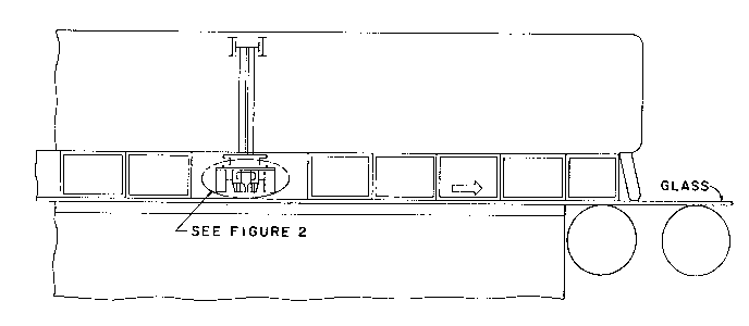
Figure 1 illustrates the position of a coater in the float
glass bath in accordance with the present invention.
Figur~ 2 is an enlarged view of the coater of Figure 1.
Figure 3 is a flow schematic of the carrier gas, coating
reactant, vaporizer and heat exchange system which feeds the coater of
35 Figure 2.
-- ~ 4 ~ 133716~
Figure 4 is a chromaticity diagram with the x and y
chromaticity coordinates measured on the corresponding x and y axes.
The wavelengths of observed colors are marked about the periphery.
Point C marks the coordinates for illuminant C in accordance with the
5 Commission Internationale de L'Eclairage (CIE). The spiral shaped
curve is a plot of the chromaticity coordinates of tin oxide films at
increasing film thicknesses. Points A and B mark the thicknesses
corresponding with the preferred coating thickness range of the
present invention.
SUMMARY OF THE lNV~NllON
The present invention provides a method for depositing a
relatively thick, non-iridescent, infrared-reflective tin oxide film
onto a float glass surface while the glass is still supported in the
tin bath in a nonoxidizing atmosphere. By coating the glass on the
15 bath, a higher glass surface temperature provides a tin oxide coating
with lower resistance and therefore lower emissivity at a given
coating thickness.
DESCRIPTION OF THE PREFERRED EMBODIMENT
Referring to Figure 1, a glass substrate, preferably clear
20 soda-lime-silica-glass, in the form of a continuous float glass ribbon
is conveyed in a horizontal position through a coating station while
the glass is supported on molten metal, preferably tin, in a float
bath in a nonoxidizing atmosphere, preferably nitrogen.
The coating apparatus illustrated in Figure 2 is located
25 above the glass ribbon at a point where the glass surface temperature
is preferably in the range of 1150 to 1250F (about 621 to 677C),
most preferably about 1200 to 1250F (about 649 to 677C). The
coating apparatus directs a gaseous stream comprising a carrier gas,
preferably air, and a coating reactant, preferably butyltin
30 trichloride, into contact with the hot glass surface, whereupon the
coating reactant thermally decomposes to form a tin oxide film.
The coating apparatus of the present invention comprises a
narrow chamber with a coating reactant inlet end, and an outlet end
substantially as long as the width of the glass area to be coated.
35 The chamber is supplied with a mixture of carrier gas and coating
reactant vapor. The coating reactant is preferably vaporized before
133716~
-- 5 --
it enters the chamber in order to save the space that would be
required to pls-e vaporizing means lnside the chamber. The chambér is
prefer3bly tapered from a cylindrical-shaped inlet end to a narrow
.lot-sll~l)ed ouclet ell~ or no~zLe whicl~ directs the vapori~.ed coating
5 reactant gaseouY mi~ture to tlle glas~ surface to be coated. Suitablc
llo~lcs are d~scribe~ ln ~I tail in U.S. I'atent Nos. 3,850,679 to Sopko
et al; 3,888,649 and 3,942,469 to Simhan.
In a most preferred embodiment, a
distributor is placed between the chamber and the nozzle to promote
10 uniform distribution of the coating reactant vapor along ehe length of
the nozzle. A preferred distributor is a structural element,
positioned over the outlet end of the chamber, having a plurality of
evenly spaced apertures through which the vapor passes into the
nozzle. Preferably, the individual jets of coating reactant vapor and
15 carrier gas are diffused before the mi~ture exits from the nozzle.
Diffusion may be accomplished by means of diffuser elements in the
inlet end of the noæzle, similar in configuration to the baffles shown
in the powder coater of U.S. Patent No. 4,344,986 to Henery.
-- ~ Preferred coating reactants for chemlcal vapor deposition of
20 a low emissivity coating in the float bath in accordance with the
present invention are organometallic compounds, preferably organotin
compounds. Many organometalllc compounds which exist in solid fortn at
ambient temperature may be employed in solution for vaporization and
chemical vapor deposition.
A variety of aliphatic and olefinic hydrocarbons and
halocarbons are suitable as solvents in carrying out the methods
disclosed herein. Single component solvent systems, particularly a
solvent system empLoying methylene chloride, are effectively employed
in the present invention. Solvent systems employlng two or more
30 solvents are also found to be particularly useful. Some
representative solvents which may be employed in car-rying out the
present invention are: methylene bromide; carbon tetrachloride; carbon
tetrabromlde; chloroform; bromoform; l,l,l-trichloroethane;
,--~ perchlorethylene; I,l,l-trichloroethane; dichloroiodomethane;35 1,1,2-trlbromoethane; trichloroethylene; tribromoethylene;
1337165
trichloromonofluoroethane; hexachloroethane;
1,1,1,2-tetrachloro-2-fluoroethane;
1,1,2-trichloro-1,2-difluoroethane; tetrafluorobromethane;
hexachlorobutadiene; te~r~chloroethane; etc. and mixtures thereof.
5 Other solvents may also be employed, particularly as mlxtures of one
or more organic polar solvents, such as an alcohol containing 1 to 4
carbon atoms and one hydroxyl group and one or ~ore aromatic non-polar
compounds, such as benzene, toluene or xylene. The volatllity of
these materlals makes thelr use less preferred than the use of the
10 above preferred halogenated hydrocarbons and halocarbons, but they
have particular economic utility.
A solution of a reactive organometallic salt in an organlc
solvent may be directed to a vaporizing chamber. The vaporizing
chamber is constructed so as to provide a heating element which heats
15 the space surrounding the element to a temperature sufficient to
vaporize the coatlng solution within that space, rather than
vaporizing the llquid only in contact with the heatlng element
itself. A carrier gas is directed across and away from the heater to
intercept the coating composition to mix with it, enhancing its rate
20 of vaporization, and to carry the vapors through the heater to the
substrate to be coated. Vapors of the solvent and organometallic
coating reactant are directed from the vaporizer to the coater sho~n
in ehe drawing.
Some preferred organometallic compounds in accordance with
25 the present invention are liquid at ambient temperature, and may be
employed without the use of solvents. A partlcularly preferred
organometallic compound is monobutyltin trichloride, a colorless
liquld, characterized by an atmospheric boiling point of 420F
(221C), a partial pressure of 0.1 atmosphere of 310F (154.4C), heat
30 of vaporization of 14.5 kilocalories and entropy of vaporization of
29.4 Clausius per mole. Monobutyltin trichloride ls preferably
vaporized by contact with hot carrier gas, typically air, preferably
maintalned at a temperature below about 400F ~204C) to avold
decomposition, typically about 385F (196C). Suitable vaporizers are
3S described in detail in U.S. Patent Nos. 3,970,037 to Sopko and
4,297,971 to Henery.
~3 .
133716~
In a preferred embodiment of the present invention. a
fractio11 of the total volume of heated carrler gas is mixed with the
monobutyltln trichloride in a vaporlzer comprislng a coil of tubing
immersed in hot oil. The heavily saturated mixture of coating
5 reactant vapor in carrier gas is then dl}uted with additional heated
carrler gas in the chamber en route to the nozzle which dellvers the
coating reactant to the glass surface. Preferably, monobutyltin
trichloride is doped with a fluorine-containing compound to enhance
the conductivity of the tin oxide film formed therefrom. A preferred
10 dopant is trifluoroacetlc acid, preferably in the range of l to 10
percent, most preferably about 5 percent by weight.
In order to minimize the possibillty of contamination of the
deposited film by unreacted or undeposited coating reactant or
reaction by-products, the coating apparatus of the present invention
15 comprises integral exhaust means. Adjacent the nozzle along
substantially its entire length is an aperture maintained at a
negative pressure to provide exhaust means for removing unreacted
coating reactant, undeposited reaction product and reaction
by-products from the coating site so that neither the freshly coated
20 surface nor the approaching surface to be coated becomes
contaminated. Since the chemical vapor deposition method of the
present invention does not depend on diffusion of the coating reactant
vapor through the normal boundary layer, it ls not limited to coating
reactants with high entropies of vaporizatlon as dlsclosed in U.S.
25 Patent No. 3,852,098 to Bloss et al.
Preferred tin oxide infrared reflecting films in accordance
with the present inventlon have a resistivity less than about 40 ohms
per square, preferably 25 ohms per square or less, and low emissivity,
preferably less than 0.2. The thickness of the film is chosen to
30 correspond with a minlmum in the luminous reflectance curve which
plo s luminous reflectance as a function of film thickness. The
preferred thickness of a tin oxide film deposited on float glass in
the bath in accordance with the present invention is in the range of
2500 to 3500 ~ngstroms, most preferably about 3200 Angstroms. A tin
35 oxide filn1 of tl1is cl1ick11ess exhibits a third order blue interference
Ir,
1~37165
-- 8 --
color as shown in Figure 4, and an emissivity as low as 0.15 when
produced in accordance with the present invention.
The advantages of depositing a tin oxide coating in the
float bath are not only the decreased resistance and lower emissivity
5 exhibited by the film, but also the improved coating uniformity which
results from temperature uniformity of the substrate provided by
contact of the glass with the molten tin in the bath, and reduced
reflected distortion which results from higher substrate coating
temperatures available without additionally heating the glass.
Referring to Figure 3, coating reactant in recirculating
pump system 10 is preheated to 350F (about 177C). Carrier air is
preheated in an air heater 20 also to 350F (about 177C). The
carrier air is supplied at 20 standard cubic feet per minute per 30
inches (76.2 centimeters) of slot length at a 3/16th inch (4.8
15 millimeter) slot width. The carrier air velocity is preferably about
950-llS0 feet ~about 290 to 351 meters) per minute. The carrier air
picks up coating reactant from supply 30 until the air is essentially
saturated. The carrier air/coating reactant vapor mixture travels to
the coating vaporizer 40 which is also maintained at a temperature of
20 about 350F (about 177C) where the coating reactant becomes
completely vaporized. The vaporized coating reactant and carrier air
mixture travels through heated transport lines 50 to the coating vapor
distributor cavities 5 shown in Figure 2. The vaporized coating
reactant is distributed through orifices 6 into the vapor cavity 7
25 from which it is directed through the nozzle 8 to the glass surface as
shown in Figure 1. After the coating reactant thermally reacts with
the hot glass surface to form a tin oxide film thereon. the carrier
air, unreacted coating reactant vapor and any decomposition
by-products are immediately exhausted in a controlled manner through
30 exhaust oriices 9 of the vacuum platens 10. The transport lines,
distributor cavities, vapor cavity, exhaust orifices and vacuum
platens are all maintained at a constant temperature of about 350F
(about 177C) by means of a circulating oil heat transfer system 11.
Negative pressure sufficient to exhaust the carrier air,
35 unreacted coating reactant and reaction by-products is supplied
through exhaust means. The upstream exhaust orifice is preferably
- 9- 1337165
about 7/8 inch wide and the downstream orifice about 1 inch. Both run
the full length of the coater nozzle. At the coating reactant and
carrier gas flow rates of the following examples, the pressure drops
measured in inches of wster are preferably about 4.3 for the upstream
5 and about 3.7 for the downstream exhaust orifices. The distance
between the coater nozzle and the glass is preferably in the range of
0.375 to 0.75 an inch (about 9.5 to 19.1 millir?ters), most preferably
around 0.5 inch (about 1.3 centimeters) as in the following examples.
The bath atmosphere is preferably pure nitrogen at a slight positive
10 pressure, preferably in the range of .05 to .07 inch (about 1.27 to
1.78 mi11im~ters), most preferably about .06 inch (about 1.5
-- millimeters), of water. The carrier air/vaporized coating reactant
mixture as in the following examples preferably comprises about 18
cubic centimeters of reactant in 25 standard cubic feet per minute of
15 carrier gas per foot of nozzle length, and is preferably supplied at a
pressure of about 4 pounds per square inch in laminar flow. The glass
line speeds may vary over a wide range, for 2.5 millimeter glass, e.g.
a range of 30 to 310 inches (about 0.76 to 7.9 meters) per minute.
The present invention will be further understood from the
20 descriptions of specific examples which follow:
EXAMPLE I
To illustrate the effect of hydrogen in the bath atmosphere
on the resistivity of a tin oxide film produced in accordance with the
present invention, films of approximately the same thickness, about
25 2600 Angstroms, were produced in various bath atmospheres. A 3.3
millimeter thick soda-lime-silica float glass ribbon is coated while
supported on molten tin in the float bath in the normal bath
atmosphere of nitrogen containing about 7% hydrogen. The upper
surface of the glass ribbon is contacted at a temperature of about
30 1227F (about 664C) with carrier air essentially saturated with
, . .
vaporized monobutyltin trichloride maintained at a temperature of
about 350F (about 177C) by means of a circulating oil heat exchange
system. A tin oxide film deposited at a thickness of about 2600
Angstroms has a resistivity of 900 ohms per square.
EXAMPLE II
lo- 13371~
A float glass ribbon is coated as in the previous example
except that the amount of hydrogen in the float bath atmosphere is
reduced to 2%. At a tin oxide coating thickness of 2600 Angstroms,
the resistivity of the tin oxide film is 125 ohms per square.
EXAMPLE III
A float glass ribbon is coated as in the previous examples
with a tin oxide film except that the float bath atmosphere is pure
nitrogen. A tin oxide film deposited at a thickness of 2600 Angstroms
has a resistivity of 25 ohms per square. At a resistivity of 25 ohms0 per square, the emissivity of the tin oxide film is 0.20.
EXAMPLE IV
A 3.3 millimeter thick soda-lime-silica float glass ribbon
is coated while supported on molten tin in a float bath in an
atmosphere of pure nitrogen. The upper surface of the ribbon is
15 contacted at a temperature of 1227F (about 664C) with air
essentially saturated with vaporized monobutyltin trichloride which is
maintained at a temperature of 350F (about 177C) by means of a
circulating oil heat exchange system. Exhaust means adjacent to the
coater nozzle remove air, unreacted monobutyltin trichloride and any
20 by-products of thermal decomposition from the coating station without
contaminating the surrounding nitrogen atmosphere. A tin oxide film
is deposited at a thickness of 3200 Angstroms. The film has a surface
resistivity of about 20 ohms per square. The coating has a third
order blue-green color and 16 percent luminous reflectance. The
25 luminous transmittance of the coated glass is 72 percent and the
emissivity is 0.17.
The above examples are offered to illustrate the present
invention, and show the importance of maintaining the surface being
coated free from a reducing atmosphere. With the apparatus used in
30 the above examples, it is preferred to eliminate hydrogen from the
bath atmosphere. However, various coating reactants, coater deslgns,
process parameters and so on are within the scope of the present
invention. While a hydrogen-free bath atmosphere may be preferred,
the coating apparatus may also be modified to exclude hydrogen in the
35 bath atmosphere from only the glass surface at which the reaction of
the coating reactant is taking place, for example by means of a
1337~6~
-- 11
nitrogen purge about the perimeter of the coater. The scope of the
present invention is defined by the following claims.