Note: Descriptions are shown in the official language in which they were submitted.
1337623
STUDDED FOOTWEAR
This invention relates to studded footwear, that
is to footwear of the kind that is provided with studs
or that can be provided with studs.
For convenience of description the term stud is
used herein to denote generally any form of projection
that in use can engage the ground, the term therefore
including both blunt projections and sharp projections
of the kind sometimes referred to as spikes.
i
Also for convenience of description, articles of
footwear, studs and their component parts are described
as if they were in the orientations they assume in
normal use.
It is common practice to provide an article of
footwear with a plurality of internally screw-threaded
sockets which are open at their lower ends. The
sockets may be in the sole or in the heel of the
article of footwear, or in both the sole and the heel.
A stud for use with an article of footwear of that kind
has an externally screw-threaded spigot which can be
screwed into a socket. It is desirable for the sockets
to be made from plastics materials rather than from
metals as in general they are lighter than the
equivalent metal sockets and, unlike metal sockets,
tend not to corrode. Nevertheless it may be necessary
or desirable to take steps to avoid the sockets being
damaged when in use. In particular, each stud may be
provided with retaining means, such as an upstanding
ring, which is spaced outwards from the screw-threaded
spigot, the arrangement being such that when the spigot
is screwed tightly into a socket, the retaining means
resists the tendency for the lower end portion of the
1337623
socket to expand outwards to an extent such as might
cause the socket to split or to be in danger of
splitting. Furthermore, the presence of the retaining
means may well enable the stud to be screwed up so
tightly that an intermediate part of the socket expands
outwards and the socket becomes slightly
barrel-shaped. This leads to relatively high
frictional forces operating between the stud and the
socket, those forces helping to reduce the likelihood
of the stud becoming unintentionally unscrewed in use.
Studs and sockets of the kind described above are
described and illustrated in more detail in the
specification of British patent application No. 8518677
(publication No. 2 163 037 A) of Triman Limited.
Nevertheless, it may sometimes happen that a stud
is not fully screwed into its associated socket or that
a stud works loose. When that occurs there is
relatively little resistance to the stud gradually
becoming unscrewed. A partially unscrewed stud in an
article of footwear can be a danger to a person wearing
that article of footwear. Moreover, when a lateral
force is applied to a projecting stud, the effects on 25 the associated socket can be damaging; not only is a
reduced length of spigot engaged in the socket, but in
addition the moment of force applied to the socket is
increased as the result of the increased length of that
part of the stud projecting from the socket. It is
therefore desirable to provide means for reducing the
likelihood of a stud becoming inadvertently unscrewed.
An aim of the present invention is to provide such
means.
1337623
.,
From a first aspect the present invention consists in the combination
of a socket and stud for an article of footwear, the stud compri~ing a
ground-~n~ging portion at one end, an PYt~rn~lly screw-threaded spigot at
its other end and teeth which are spaced ouLwdl~s from the spigot so that an
5 annular gap is formed beLw~ the spigot and the teeth, and the socket being
an int~rn~lly screw-threaded unitary moulding of a plastics m~t~ri~l
compri~ing a tubular portion with complem~nt~ry teeth on its radially outer
surf~e, the al~allgelllent being such that in an assembled condition of the
stud and socket, when the spigot is screwed into the socket, a leading end
10of the tubular portion is received into said annular gap and the teeth of the
stud surround said outer surface of the socket, the teeth of the stud and the
teeth of the socket being inL~ gaged to prevent the stud being freely
unscrewed.
15The teeth on the stud are plt;r~l~bly frangible, the arrangement being
such that when the spigot of the stud has been screwed into the socket and
the teeth on the stud and socket have become inL~lc;l~gaged to at least a
predetermined extent, the action of unscrewing the stud from the socket
causes at least some of the teeth on the stud to break off.
The a~ gelllent is preferably such that in whaLt;vtir relative
rotational positions the stud and socket are when the stud is screwed into the
socket, at least some of the teeth on the stud are free to assume their natural
shapes rather than being deformed by contact with the teeth on the socket.
25 This can conveniently be achieved by making the number of teeth on the
socket different from the number of teeth on the stud. The number of teeth
on the socket is preferably less than the number of teeth on the stud. The
teeth on the socket are preferably lmiformly spaced around the socket, and
~imil~rly the teeth on the stud are preferably unirollllly spaced around the
30 spigot.
From a second aspect the present invention consists in a stud with
an externally screw-threaded spigot which can be screwed into an int~rn~lly
1337623
screw-threaded socket, for an article of footwear, the
stud being characterised in that it is provided with
teeth which are spaced outwards from the spigot and can
engage complementary teeth on the outside of the-socket
when the spigot is screwed into the socket, that
interengagement serving to prevent the stud being
freely unscrewed.
The teeth on the stud are preferably
ratchet-shaped so that the faces they present to the
teeth of a complementary socket, when the stud is being
screwed into such a socket, are inclined to the axis of
rotation and afford less resistance to rotation than
would occur if the faces were parallel with the axis of
rotation, while the faces they present to the teeth of
that socket when a torque is applied to the stud in the
direction necessary for the unscrewing of the stud from
the socket are either not inclined to the axis of
rotation or are inclined more steeply than the
aforementioned faces. The teeth on the stud are
preferably provided on a retaining ring spaced outwards
from the spigot and adapted to receive an end portion
of a complementary socket in the manner and for the
purpose described above.
The spigot and the teeth of the stud are
preferably formed from a plastics material as parts of
the same moulding. The stud preferably has an
outwardly directed flange, disposed below the spigot
and the teeth, which flange can in use engage the
underside of the article of footwear on which the stud
is mounted. The lower surface of the flange is
preferably of a convex shape, though if desired it
could be flat or even concave.
1337623
-
From a third aspect the present invention consists
in an internally screw-threaded socket, for an article
of footwear, the socket being characterised in that it
is provided on its outer surface with a plurality of
teeth for interengagement with complementary teeth on a
stud having an externally screw-threaded spigot which
can be screwed into the socket, that interengagement
serving to prevent the stud being freely unscrewed.
The teeth on the socket are preferably ratchet-shaped
so that the obstruction they afford to the teeth of a
complementary stud when it is being screwed into
engagement with the socket is less than the obstruction
they afford to the teeth on such a stud when it is
being unscrewed from the socket. The teeth on the
socket are preferably set back from the lower end of
the socket so that an end portion of the socket,
without teeth, can be received by complementary
retaining means on a stud.
The socket could comprise an individually formed
component, unconnected to any other socket, and
anchored or adapted to be anchored in an article of
footwear, but in a preferred arrangement the socket is
one of a plurality of similar sockets constituting part
of a socket unit incorporated in or adapted to be
incorporated in an article of footwear. The socket
unit may be incorporated in the sole of an article of
footwear or in the heel thereof. A unit designed for
incorporation in the sole will be referred to below as
a sole plate. The socket unit may be fabricated from
pre-formed components but is preferably formed as a
unitary mouLding of a suitable plastics material or the
like. The moulding is preferably in the form of a
plate from the underside of which a plurality of
sockets project. The upper face of the plate is
preferably flat. Likewise, the lower face of the plate
` 1337623
-
may also be flat, though if desired it may be shaped so
that certain areas of the plate, notably around the
socket, are thicker than other areas. In a preferred
arrangement, thicker areas of the plate form bands,
each of which extends across the plate between a pair
of associated sockets. The arrangement is preferably
such that when the unit is incorporated in the sole of
an article of footwear, at least some of the bands
extend laterally across the article of footwear rather
than lengthwise thereof.
The outer surface of each socket preferably flares
upwards and outwards above the teeth. In use, when the
socket unit is incorporated in a shoe, the sockets
project downwards into holes formed in a bottom part of
the sole or heel. The holes are sufficiently large to
accommodate the sockets and the teeth on the sockets.
The flared part of the outer surface of each socket can
engage and slightly deform that part of the bottom of
the sole or heel bordering the upper end of the
associated hole; consequently the plate is positively
located relative to the bottom part of the sole or heel.
While the bottom part of the sole or heel is 25 normally likely to comprise a single layer of leather
or other material, such as a plastics material, it
would be possible for the bottom part of the sole or
heel to comprise two or more separately formed laminae
of the same or of different materials.
From a fourth aspect the present invention
consists in an article of footwear provided with a
plurality of downwardly opening sockets, each in
accordance with the third aspect of the present
invention.
133762~
`_
From a fifth aspect the present invention consists
in an article of footwear in accordance with the fourth
aspect of the present invention, in combination with a
plurality of studs for said sockets, each stud being in
accordance with the second aspect of the present
invention.
An embodiment of the present invention will now be
described in more detail, by way of example, with
reference to the accompanying drawings, in which:
Figure 1 is a view from beneath of a sole plate
for incorporation in a golf shoe, but with some
parts thereof omitted for clarity,
Figure 2 shows details of a socket and is a
section, to a larger scale, on the line 2-2 of
Figure 1,
Figure 3 is a view from beneath of the socket
shown in Figure 2,
Figure 4 shows details of a tooth on the socket
and is a side view of part of the socket shown in
Figure 2, as viewed-in the direction of the arrow
A in Figure 2,
Figure 5 is a view from beneath of the support
or body of a stud for use with a socket of the
kind shown in Figure 2,
Figure 6 is a section on the line 6-6 of
Figure 5,
Fiyure 7 shows details of a tooth on the stud
and is a side view of part of the stud shown in
1337623
~ ,
Figure 6, as viewed in the direction of the arrow
B, and
Figure 8 is a scrap section through a socket with
a stud support screwed into it, the socket forming
part of a modified form of sole plate.
The sole plate illustrated in Figure 1 is intended
for incorporation in the sole of a golf shoe, as
described in more detail below. The sole plate
comprises a unitary moulding of a suitable plastics
material such as an acetal resin. The upper side (not
shown) of the plate is flat, but the underside is
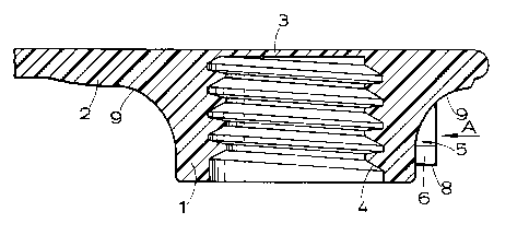
shaped to provide various formations. Principal among
those formations are a plurality of sockets, 1, and a
plurality of bands, 2. There are eight sockets in this
particular embodiment but it is to be understood that a
different number of sockets may be provided, if
desired. Similarly the number of bands may be varied
as desired.
The sockets are all of the same shape and size, so
only one will be described in detail. The socket is
open at its lower end and is closed at its upper end by
an integral closure disc 3 which is relatively thin as
compared with the thickness of the remainder of the
plate. The socket is formed internally with a
screw-thread 4. The profile of the thread is similar
to that described and illustrated in the specification
of British patent No. 2 115 683 of Triman Limited and
will not be further described here. A plurality of
teeth 5 are formed on the outside wall of the socket.
For the sake of clarity, the teeth are not shown in
Figure 1. In the embodiment illustrated in Figures 2
and 3 there are five such teeth, but a different number
may be provided if desired. The teeth 5 are spaced
1337623
_
uniformily around the socket and are all of the same
shape and size. As can be seen from Figure 4, each
tooth is ratchet-shaped, having on one side a face 6
which is inclined to the axis of the socket and on the
other side a face 7 which is parallel with that axis.
The faces 6 and 7 are joined at their lower ends by a
short end face 8 which is normal to the axis. The
teeth are set back, above the lower end of the socket,
as illustrated. The outer surface of each socket
flares upwards and outwards above the teeth, as
indicated at 9.
Each of the bands 2 constitutes an area of
increased thickness of the plate and extends between
two associated sockets. A central part of each band is
of uniform thickness and is bordered on each side by a
wedge-shaped part. In this way, sudden variations in
thickness are avoided. An end portion of each band
surrounds a socket and provides increased support for
the socket. The bands 2 extend in a generally
transverse direction across the width of the plate, and
in consequence the bands do not interfere significantly
with the transverse flexing of the sole plate such as
can be expected to occur in use. It will be seen from
Figure 2 that the closure disc 3 at the upper end of
each is less thick than the main part of the plate;
this enables the axial length of the interior of the
socket to be made as long as possible.
The sockets 1 are intended for receiving studs.
Each stud comprises a support 10 made of a plastics
material such as an acetal resin and a metal pin
element (not shown). The support 10 comprises an
externally screw-threaded sleeve 11 which constitutes a
spigot to be screwed into one of the sockets 1. The
support also includes an outwardly directed flange 12.
1337623
The pin element comprises a stem and a ground-engaging
head. In manufacture, the stem is inserted into the
sleeve 11 and is deformed after insertion to secure the
support and pin element permanently together. Studs of
that kind are the subject of British patent
No. 2 008 102 of Triman Limited and their construction
will not be further described here. An annular
retaining ring 13 projects upwards from the flange 12.
The ring is spaced outwards from the sleeve 11 and is
co-axial with it. In use, when the spigot is screwed
into a socket, the lower end portion of the socket,
below the teeth 5, enters the ring. The function of
the retaining ring is described in British patent
application No. 8518677 (publication No. 2 163 037A)
referred to above and will not be further described
here.
A plurality of teeth 14 project upwards from the
top of the retaining ring 13. In the embodiment
illustrated there are ten such teeth, but a different
number may be provided if desired. Nevertheless, for
reasons described below it is preferred to provide
twice as many teeth on the stud as there are on the
socket. As can be seen from Figure 7, each of the
teeth 14, is rachet-shaped, having a leading face 15 of
curved shape, but of which an upper part is
considerably inclined to the axis of the stud, and a
trailing face 16 which is almost parallel with that
axis.
The flange 12 is generally saucer-shaped, having a
convex underside and a concave upper side. Blind
holes 17 are formed in the underside of the flange and
serve to accept pins on a face spanner used for
screwing the stud into and out of a socket. The blind
holes 17 could be replaced by through holes if desired,
1337623
though it is usually preferred to provide blind holes
as through holes might provide a passage for dirt to
enter and become trapped between the flange and the
bottom of the article of footwear. The rim of the
flange is of a shape unlike that of the flanges of the
previous designs of stud in that its upper side tapers
upwards. The taper is afforded by a frusto-conical
face 18 which extends above an outermost cylindrical
face 19. The provision of an upwardly tapering rim on
the flange of a stud is of general application and is
not restricted to studs of the kind that are the
subject of the present invention.
It is, of course, to be understood that the rim of
the flange may be of any other desired shape. For
example, it may present a relatively sharp edge or a
rounded edge; alternatively it may have an upstanding
peripheral rib which in use tightly seals against the
sole or heel of the article of footwear.
The sole plate and the associated studs is
intended to operate in the following manner.
The sole plate is incorporated in a golf shoe
which includes a sole of which the bottom part is made
from a piece of leather. In manufacture, the piece of
leather is trimmed to a substantially uniform thickness
and is punched with circular holes so positioned that
each hole can receive an associated one of the
sockets 1 of the sole plate. The diameter of each hole
is just great enough to enable the teeth 5 on the
associated socket to enter the hole. If desired the
hole-size may be such as to require the sockets to be
lightly pressed into the holes so that the sole plate
is held in place by friction. The leather around the
lower end of each hole is milled away to provide a
133762~
shallow counterbore of a diameter slightly less than
that of the cylindrical outer face 19 of the flange 12
of the stud. When the sole plate has been assembled
with the piece of leather, with the sockets 1
projecting downwards into the holes, the lower end of
each socket, below the teeth 5, is either flush with
the upper end of the counterbore or projects a short
way into the counterbore. The flared part 9 of each
socket engages and slightly compresses that part of the
leather bordering the upper end of the associated
hole. The central parts of the bands 2 bear on the
upper face of the piece of leather but gaps are left
between the remainder of the sole plate and the
leather. If desired those gaps could be filled with
suitable packing material but that is not normally
considered necessary.
The piece of leather assembled with the sole plate
is then incorporated in the remainder of the shoe in a
conventional manner. In the course of manufacture the
piece of leather tends to assume a lightly curved shape
so that its undersurface is convex.
After the shoe is completed the spigots of the
studs are screwed into the sockets. While each stud is
being screwed into position, the teeth 14 on the stud
soon start to come into contact with the teeth 5 on the
socket. As the leading faces 15 of the teeth 14
contact the inclined faces 6 of the teeth 5, the
teeth 14 initially tend to yield resiliently and to
ride past the teeth 5. As the spigot rises
progressively in the socket, however, the teeth 14 tend
to splay outwards as they pass by the teeth 5. In so
doing they tend to press into the leather bottom part
of the sole bounding the hole in which the socket is
housed. Were it not for the presence of the leather
- 1337 623
there might also be a tendency for the teeth 5 to
become deformed. The presence of the leather, however,
which abuts the part-cylindrical outer face of the
tooth, does tend to prevent that happening.
s
When the stud is fully screwed into place, the
lower end of the socket abuts the upper surface of the
flange 12 inside the retaining ring 13. There are then
strong frictional forces resisting the unscrewing of
the stud. Meanwhile the rim of the flange 12 has
entered the counterbore in the leather bottom part of
the sole, and the frusto-conical face 18 of the rim has
lightly and resiliently crushed the leather bordering
the counterbore. This arrangement has several
advantages. One is that in entering the counterbore,
the rim of the flange tends to pull the counterbore
into a more truly circular shape, for it is likely to
have become slightly elliptical during manufacture
owing to the fact that the leather has become slightly
curved. Another advantage is that the extent to which
the flange 12 projects below the shoe is much reduced,
and the resultant indentation of any golfing green on
which a user may walk is correspondingly lessened. In
fact, only a central part of the flange projects below
the level of the adjacent part of the undersurface of
the shoe. Finally, another advantage is that when the
shoe is in use and the sole flexes, any slight relative
movement that may occur between part of the sole and
part of the flange 12 is normally insufficient to cause
the rim of the flange to leave the counterbore. Thus,
no gap appears between the flange and the sole into
which earth or grass might enter in use.
As described above, there are often a number of
advantages in providing counterbores in the underside
of an article of footwear for receiving the outer parts
- ~ ^ 1337623
14
of the flanges of the studs. Nevertheless, the
provision of counterbores is not an essential feature
of the present invention, and they may, if desired, be
omitted. In such cases the lower ends of the sockets
may then be flush with the underside of the article of
footwear or may project below the underside.
Also, when the stud is fully screwed into place
the end faces 8 of the teeth 5 are spaced only a very
small distance above the upper edge of the retaining
ring 13. It is quite likely that the five teeth 5 are
engaged by five of the teeth 14, and that those
teeth 14 are inclined outwards into the leather. The
remaining five of the teeth 5, however, remain
unengaged and return to their original shapes.
If, now, for any reason the stud starts to work
loose, the trailing faces 16 of the teeth 14 lying
between the teeth 5 soon come into abutment with the
faces 7 of the teeth 5 and thus prevent further
rotation of the stud relative to the socket. As the
abutting faces of the teeth are substantially parallel
with the axis of rotation, there is considerable
resistance to further unscrewing of the stud.
Nevertheless, if it is desired to remove the stud
entirely, for example when the ground-engaging head of
the pin element has become worn, the stud can be
unscrewed with the aid of a suitable face spanner. As
the stud is rotated, those of the teeth 14 that are
splayed outwards and are pro~ecting into the leather
snap off and become embedded in the leather, while the
remainder of the teeth, which quickly come into
abutment with the teeth 5 also snap off. When the stud
is finally withdrawn, those teeth 14 that were embedded
in the leather drop free quite readily. The removal of
the teeth 14 from the stud make the stud unsuitable for
1337623
-
re-use and enable the used stud to be readily
distinguished from a new, unused stud.
If it so happens that during its installation the
stud is not quite fully screwed into the socket, there
are few frictional forces helping to hold the stud in
place. The interengagement of the teeth, however, in
the manner described above, normally serves to prevent
the stud becoming unscrewed, either wholly or partially.
In the manner of operation described above, the
teeth 14, in passing the teeth 5, tend to splay
outwards and enter the surrounding leather. It might
be expected that a permanent annular groove would
therefore be formed in the leather, but it is in fact
found that this does not occur and that the leather
gradually returns substantially to its initial shape.
This is thought to be a consequence of the fibrous
nature of leather. This helps in snapping off the
teeth, as described above. Nevertheless, if a plastics
material is used instead of leather (and that is a
possible alternative), a more permanent groove may be
formed by the teeth 14 as the stud is being screwed
into place. This, however, is not fatal to the
operation of the invention as the unsplayed teeth 14
prevent the unintentional unscrewing of the stud, as
described above. Moreover, when the stud is positively
and forcefully unscrewed, the unsplayed teeth 14 snap
off on engagement with the teeth 5, while the splayed
teeth tend quickly to resume their initial shapes and
may also be snapped off by abutment with the teeth 5.
Even if a few of the splayed teeth pass outside the
teeth 5 and remain on the stud, the absence of the
remainder is immediately evident.
- _ 13376~3
Somewhat unexpectedly it has been found that when
a shoe of the kind described above has been used, there
is little or no tendency for the leather (or other)
part of the sole below the sole plate to be pressed up
between the bars 2 of the sole plate and thus display
an uneven surface. In fact, the bottom surface of the
shoe tends to remain unaffected by the presence of the
ribs 2 and the gaps between them.
It is desirable to avoid or overcome any tendency
there may be in use for the holes in the bottom part of
an article of footwear to open out. In the embodiment
of the invention described above, for example, where it
is intended that the rim of the flange 12 should seat
tightly in the associated counterbore in the bottom
part of the sole or heel, it is desirable to avoid or
overcome any tendency for the counterbore, with its
associated hole, to open out. Moreover, in the
embodiment described above, the provision of the flared
part 9 on each socket may tend to displace downwards
that portion of the bottom part of the article of
footwear immediately bordering the hole, so that the
lower end of the hole is encouraged to flare outwards.
To overcome or reduce such problems or tendencies
there may be provided a formation on or in the
underside of the socket unit extending around each
socket, each formation affording, within it, an
upwardly extending recess somewhat larger in extent
than the flange on the associated stud so that in use,
when the stud is tightened into place its flange tends
to urge the adjacent part of the bottom part of the
article of footwear into the recess. The formation may
be formed merely by providing a recess, such as a
circular recess, in the socket unit. Preferably,
however~ the formation comprises an annular rib
1 337623
-
concentric with the associated socket and of a diameter
somewhat greater than that of the rim of the associated
stud. An embodiment of the invention incorporating
such a rib is illustrated in Figure 8 in which there is
shown part of a sole plate 20, with a socket 21 similar
to the socket 1 shown in Figures 2 and 3. The sole
plate 20, however, differs from that shown in Figure 1
in that its undersurface is not provided with the
bands 2 and is flat over most of its extent. The
support 22 of a stud is shown as being fully engaged
with the socket 21, the support being of the same
design as that of the support 10 illustrated in
Figures 5 and 6. Parts of the socket 21 and support 22
are given the same reference numerals as those given to
corresponding parts o~ the socket 1 and support 10. An
annular rib 23 is formed on the undersurface of the
sole plate 20. The rib is of semi-circular
cross-section and is concentric with the socket 21. A
similar rib is formed round each socket of the sole
plate.
The bottom part of the sole is indicated by the
chain-dotted line 24. Initially it is of uniform
thickness and is formed with a hole 25 for receiving
the socket 21. The hole has a counterbore 26 at its
lower end for receiving the rim of the flange 12 of the
support 10. As described above, that part bordering
the top of the hole 25 is slightly deformed by the
flared part 9 of the socket, while the rim of the
flange lightly compresses the part bordering the
counterbore. In use, when the stud is screwed fully
into place in the socket, the rim of its flange 12
presses up against the bottom of the shoe. That part
of the bottom of the shoe vertically above the rim and
adjacent to the socket unit is disposed just inside the
annular rib 23 on the unit. The upward force applied
1337623
18
by the rim of the flange to this part of the bottom of
the shoe, which is indicated by the arrow 27, tends to
press the bottom of the shoe upwards against the socket
unit just inside the annular rib. The rib 23 therefore
exerts a downward force on the bottom part of the sole,
as indicated by the arrow 28. Consequently that part
of the bottom of the shoe between the annular rib 23
and the hole 25 is subjected to a couple which tends to
urge it radially inwards so as to assume a shape such
that the lower end of the hole 25, with the
counterbore 26, is reduced in diameter, while the upper
end of the hole is urged radially outwards. The height
of the annular rib 23 need not be great to achieve the
desired effect.
The embodiment of the invention described above
with reference to the drawings relates largely to a
sole plate, but it is to be understood that it is
equally applicable to a socket unit for incorporation
in the heel of a golf shoe or other article of
footwear.
It will also be appreciated that the provision of
an annular rib 23 or of some other formation preforming
a similar function is applicable to other kinds of
socket units and in particular may be of value with
socket units in which the sockets are not provided with
teeth and co-operate with studs that are not provided
with teeth.