Note: Descriptions are shown in the official language in which they were submitted.
- - 2 - I 3378 1 2
The present invention relates to an apparatus to provide for the
storage and controlled release of products that are
underpressure. Compared with conventional spray cans, this
apparatus, makes it possible to use either a reduced quantity of
liquid gas or else compressed gases as the propelling force.
The ban on halogenated hydrocarbons, known under the
names of FRIGEN or FREON (Trademarks), has led to the extensive
use of hydrocarbons such as propane and butane, or dimethylether
and mixtures of these. Both FRIGEN and FREON are hazardous for
the ozone layer that surrounds the earth, and butane and propane,
as well as dimethylether, are dangerous for the filling industry
because of their explosive characteristics, as well as for the
user, since deaths have been caused by the explosion of these
substances.
In addition to these flammable gases, it is known that
non-flammable, only partially halogenated FREON 22, (chemical
formula CHClF2) can be used as a propellant. This can also be
used in the USA and in the Scandinavian countries, where both
FREON and FRIGEN are banned, because FREON 22 contains an
additional hydrogen atom and, for this reason, is not as
persistent as the fully-halogenated hydrocarbons. Since, however,
the vapour pressure of the non-flammable FREON 22 is extremely
high and at 20C is approximately 9 bar, it must either be mixed
with a gas of lower vapour pressure, such as dimethylether or
butane (which are flammable), or else used in reduced quantities,
which is to say, between 18-50~-wt, depending on container
133781 ~
- 3 - 24410-7
quality. In particular, its use in glass vessels, without any
plastic, for toilet preparations is problematic, because a
pressure of 1.5 bar at 20C must not be exceeded but, depending on
the content of water or ether oil, this pressure is reached at
18%-20% of FREON 22. Since, however, the atomizing quality of
conventional sprays depends to a great extent on the proportion of
liquid gas, and thus on its expansion, or better, explosive force
in contact with the atmospheric pressure, a percentage of
approximately 20% FREON 22 in place of the normal 50% FREON 114/12
is not sufficient to atomize toilet water such that the size of
the droplets is so fine that the spray will be perceived as "not
wet."
Metal cans are also subject to pressure limits imposed
by law, so that here, too, one has to work with smaller quantities
of FREON 22 that are smaller than those used in conventional spray
cans.
The search for a solution for the problem described
above has led to a spray nozzle as described in European patent
number 0000688 which produces extremely fine vaporization by
purely mechanical means. In addition, apparatus has been
developed as described in European patent number 0057226 and
0109361, and in PCT-application CH86/00103, published on 20th
January 1987 under the number WO87/00513, in various embodiments:
these permit the use of compressed air instead of liquid gas as
the propellant, when, despite a diminishing propellant pressure,
an almost constant ejection rate per unit time and a steady
particle size are achieved.
t ~37~ 1 2
- 4 - 24410-7
Both the use of a reduced quantity of liquid gas, of
only approximately 20~, or of compressed air, lead to
difficulties. The aerosols that are commercially available all
experience some leakage of the product after use, despite the fact
that the valve has been closed. If such a valve is used with a
high (normal) percentage of liquid gas, one cannot detect this
leakage, because when in their liquid phase these gases
simultaneously serve as solvents and, mixed with the active
product, are expelled in liquid form when the valve is opened
which leads, when in contact with atmospheric pressure, to an
explosion-like vaporization of both the liquid gas as well as of
the product carrier, such as alcohol or water. If, however, one
uses compressed gas such as air or nitrogen as the propellant, or
if one uses a lower percentage of liquid gas, e.g. of less than
25~, then this rapid-vaporization factor is either absent or else
is so small that the violent vaporization that conceals the
leakage or after-flow does not take place.
This leakage or after-flow can be attributed to several
factors. In the so-called "male" valves, a plunger is provided
with side holes which, when the valve is closed, lie within the
substance of the rubber seal, so that no product can escape.
Since, however, the central hole of the seal is stamped out, it
has
1337812
vertical grooves that are parallel to its axis, the depths of
these varying as a function of the quality or amount of wear in
the die, and through which the product can leak once the valve
has been closed, until such time as the rubber creeps into the
side holes of the plunger and closes them off. In so-called
"female" valves, the valve is closed off by the annular rib of a
plunger penetrating into a rubber gasket. The edge of most
annular ribs is 0.4 to 0.5 mm wide, which means that, depending
on the hardness of the rubber, the plunger will penetrate into
the seal slowly, which can also lead to a leakage through such
valves once they have been closed.
Depending on the quality of the valves, up to 0.03 ml can leak
out each time the valve is opened. This leakage is not only
messy; it can also lead to blockage of the vaporizer nozzles,
especially in the case of hair spray, caused by drying out of the
film binders if the propellant force is generated by a lower
percentage of liquid gas or compressed gas. The use of
compressed gases or a lower proportion of liquid gas also causes
other problems in that, because of a lack of pressure, not all
the product can be expelled from the container.
In a spray can that is filled with liquid gas ,the pressure is
built up once again after every use by the continuing
gasification of the liquid phase when, as a result of the can
being emptied, the pressure drops as a result of physical laws,
- 6 - 1337-812
so that for all practical purposes there is a constant pressure
in the can. At a lower percentage of liquid gas the quantity of
gas is just sufficient to keep the pressure constant and to expel
all the contents from the container. However, if one sprays for
too long a period during one valve opening, this gasification
leads to a cooling of the can, which then slows down the
gasification, which means that not only does the pressure fall
but more liquid gas than is intended is expelled and, for this
reason there is insufficient to empty the can. Even if the can
is used with the spray head underneath, the gas will be lost so
that once again there will not be enough of it.
This problem is much more serious when compressed gas is used as
a propellant because then the pressure cannot build up again.
Depending on the position of the can, all the pressure can be
completely lost, so that the remaining contents of the can, which
can no longer be expelled, are wasted.
Despite the sealing that is used there can be a loss of pressure
between the valve plate and the neck of the can. For example, if
aluminum cans are produced by deep-drawing aluminum disks, when
grooves that are parallel to the axis of the can are formed in
the outer wall of the can, and which, depending on the diameter
of the can, can be between 0.02 and 0.08 mm deep, but which are
so narrow that the outer rubber seal cannot penetrate into them
and thus cannot seal them off. Even though these grooves can be
- 1 3378 1 2
qround out or filled with a coat of lacquer, depending on the
type of can that is involved, there is still a loss of pressure
if the valve is not installed with the necessary precision.
A loss of pressure in compressed gases caused by holding the can
incorrectly can be avoided by using a two-chamber system, in
which the product is stored in a flexible inner container and the
propellant, compressed gas, is stored in a rigid outer
container. The latter acts on the flexible inner container and
compresses this, which means that the product contained therein
is expelled. Such systems are known. Their flexible inner
containers must, however, be installed prior to the attachment of
the base of the can or, in the case of monobloc cans, before the
shoulder section is rolled. In addition, filling the cans with
compressed gas is relatively complicated and demands a high level
of precision, which is costly, since the base of the can is
provided with an opening which can be closed by means of a rubber
stopper, next to which, if it is not completely pressed into the
opening, the compressed gas is introduced into the can, whereupon
the rubber plug is pressed completely into the opening, which it
then seals hermetically. In addition to the necessary precision,
this charging procedure takes up a great deal of time so that
mass production becomes extremely costly.
Metal cans require many times the energy--both for the production
of the metal as such and also for the production of the cans--
_ 8 1 3378 1 2 24410-7
than is required to produce plastic, and cans of this material.
Corrosion problems may also be encountered, depending on the type
of metal that is used.
In order to avoid pressure losses caused by incorrect
manipulation of the can when compressed gases are used there are
valves on the market which, thanks to a ball, make it possible to
spray the product even if the can is held upside down. However,
such cans cannot prevent a loss of pressure if the can is held in
an inclined position and the riser tube for the valve, because it
is nearly always curved, is not in, but out of, the product.
The present invention provides apparatus for the storage
and controlled dispensing of pressurized products, comprising a
rigid outer container, a flexible inner container, which is
fastened on a valve unit, said inner container comprising a folded
plastic film produced by means of heat-welding seams, and a
dispensing unit, characterized in that the valve unit contains a
valve body with a tubular part which has at least two at least
approximately radially protruding side fins, said side fins
consisting of the same plastic material as the inner wall of the
flexible inner container, the flexible inner container having a
welded surface extending over the entire width of its upper end
and joining upper overlapping edges of the folded plastic film,
wherein the tubular part of the valve body is sealed centrally
into this welded surface by heat welding between the overlapping
edges of the folded plastic film in such a way that the side fins
extend along the meeting points of the film edges on the tubular
part of the valve body.
The invention is described in greater detail below on
8a l 3378 ~ 2 24410-7
The invention is described in greater detail below on
the basis of advantageous, but not restrictive, embodiments shown
in the drawings appended hereto. These drawings show the
following:
Figure 1: a cross section through the object of the
present invention, when filled;
Figure 2: a cross section through a valve unit before a
bag is welded on and prior to its introduction into a plastic
container;
C-
1 3 3 ~
Figure 3: a cross section through a valve plunger;
Figure 4: a plan view of the valve plunger as in figure 3;
Figure 5: a cross section through a closed valve;
Figure 6: a cross section through an open valve as in figure 3;
igure 7: a view of an embodiment of a welded bag prior to said
bag being filled;
igure 8: a side view of this bag, which is secured to a valve;
igure 9: a cross section through a metal core installed in a
plastic tube, prior to the welding of a bag;
igure 10: a cross section through the object of the invention as
in figure 9, installed between two welding blocks;
igure 11: a view of a bag after being welded onto the plastic
tube as in figures 9 and 10;
igure 12: a view of valve in which the valve body is provided
for direct welding of a bag;
igure 13: a perspective view of the valve body as shown in
figure 12, between two welding blocks;
igure 14: a plan view of a bag after being welded onto a valve
body as in figure 12;
igure 15: a partial view of a bag after being welded onto the
valve body as in figure 12;
igure 16: a view of a valve unit supporting a folded bag;
igure 17: a cross section through a metal can with a greatly
enlarged neck, with a metal valve plate;
igure 18: a cross section through the neck of a plastic can with
a greatly enlarged can neck with a metal valve plate;
t337812
- 10 - 24410-7
Figure 19; a cross section through a valve unit for viscose
products such as oils, creams, pastes, gels, and the
like.
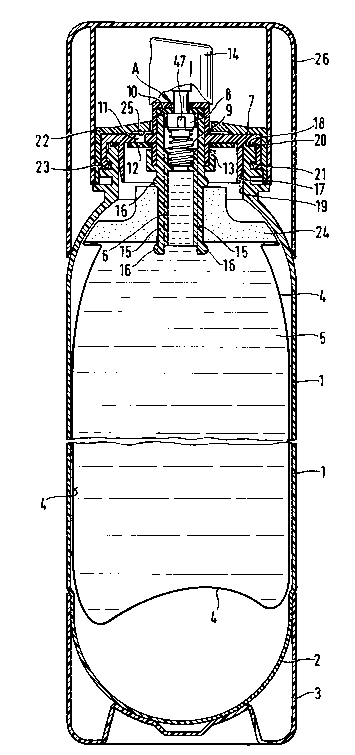
Figure 1 shows an apparatus according to the present
invention. The container 1, in this instance preferably of PET
(polyethylene terephthalate), has a hemispherical bottom 2 that is
provided with a base cap 3 to enable it to stand upright. This
container 1 contains the bag 4 in which the product 5 is stored.
The bag 4 is welded onto the valve body 6 that is secured to the
plastic valve plate 7, and contains the plunger 8, which is
pressed hard against the rubber seal 10 by means of the spring 9
and penetrates partially into this seal. The plastic valve plate
7 is provided with a hole 11 which, when the container 1 is under
pressure, is closed by means of the rubber seal 12, that's
retained by the flange 13 of the valve body 6, if the container 1
is not yet under pressure. The plunger 8 supports the spray head
14. In order to seal the container 1 hermetically and thus avoid
any loss of pressure, the plastic valve plate 7 is provided with
an annular membrane 17 and the double annular rib 18, the ring
membrane 17 closing the neck 19 of the can and the annular rib 18
closing the annular groove 20. When this is done, the annular
membrane 17 and the annular rib 18 are drawn into their seats by
means of the snap closure 21. The closing sleeve 22 prevents the
snap closure 21 from opening and, because it is
- 1 3378 t 2
- 11 - 24410-7
welded at 23 to the container 1, ensures that the latter is
hermetically sealed. Figure 2 shows these details at larger
scale. As is explained in greater detail in conjunction with
figures 12 to 15, the valve body 6 is provided with side ribs 15
which form the bead 16 after the bag 4 has been welded on by
means of the welded surface 24. The underside of the closing
sleeve 22 has an annular groove 25 that prevents the hole
11 from being covered over so that this hole is not
visible from the outside, although the container 1 can be
pressurized through it from the outside, when the seal 12 then
acts as a non-return valve. Finally, the apparatus according to
the present invention is closed with the valve cap 26. The
apparatus is assembled and charged as follows:
As is shown in figure 16, the valve unit A supports a folded bag
4 which is kept folded by means of a paper ring 79 at the valve
end and a paper ring 80 at the opposite end. The thickness of
the paper used in the rings 27 and 28 is so selected that when
the bag 4 is filled they tear in the interior of the container 1,
thereby ensuring that the bag 4 unfolds. The valve unit A with
the folded bag 4, which behaves for all practical purposes like a
"normal" riser tube and can be sorted by any commercial filling
machine, is introduced into the container 1 by machine until the
one part of the snap closure 21 snaps into the corresponding part
of the neck 19 of the can, whereupon the closing sleeve 22 is
welded onto the neck 19 of the can at the level 23, this also
- 12 - 1337812
being done by machine. This not only prevents the snap closure
21 from releasing, but also ensures that, because ultrasound
welding, with which the closing sleeve 22 (which is of the same
material as the neck 19 of the can) is joined homogenously with
this, it also provides a perfect seal for the apparatus according
to the present invention. There is also a further seal that
results from the fact that the annular membrane 17 is locked into
the neck 19 of the can and the double annular rib 18 is locked
into the annular groove 20. This method of sealing is important
in order to avoid any loss of compressed air, which could lead to
the fact that, because of a lack of propellant force, not all of
the product 5 can be driven out of the container 1. Prior to the
installation of the spray head 14 or of another dispensing
element, the bag 4 is filled with the product 5 through the valve
body 6 by forcing the plunger 8 away from the seal 10. Once this
has been done and a special filler head has been installed on the
closing sleeve 22, compressed air is introduced into the
container 1 through the drilled hole 11 in the valve plate 7,
which then places the product contained in the bag 4 under
pressure. After installation of the spray head 14 or, depending
on the properties of the product, of another dispensing element,
the apparatus according to the present invention is ready for
use. Finally, it is closed by means of the valve cap 26.
The leakage of product from the valve once said valve has been
closed, discussed heretofore, is eliminated because of the
- 13 - 1 3378 1 2
plunger 8 according to the present invention. This plunger is
provided with the annular ribs 27, 28, and 29, which result in
the annular grooves 30 and 31. As is shown in figure 3, the
annular ribs 27, 28, and 29 penetrate the seal 10, which means
that this is forced into the annular grooves 30 and 31, which
results in the immediate closing of the valve unit A.
If the valve unit A is used with compressed air as the
propellant, it will require a greater cross section and a
plurality of flow channels 32 and 33, as is shown in figure 4, in
order to ensure the greatest possible thrust, especially after a
reduction of pressure.
A version as is shown in figures 5 and 6 will be required in
order to use the valve according to ~he present invention for
aerosol cans that use liquid gases, the percentage of which has
had to be reduced because of excessively high vapour pressure, or
the quantity of which is to be reduced for reasons of safety,
which means that there will be some leakage once the valve has
been closed, as has been described above. The valve unit A
according to the present invention consists of the valve body 34
that is provided with the riser tube holder 35, the plunger 36
with the pin 37, the spring 38, the inner seal 39, the valve
plate 40 with the container seal 41, and the plunger tube 42.
The valve plate 40 is provided with the hole 43 which,
when a container that is closed by means of the valve unit A is
_ - 14 - I 337~ 3 2
under pressure, is sealed off by means of the sealing washer 44
that is held with the flange 45. The base of the valve body 34
is provided with the ribs 46 on which the spring 38 lies. By
this means, the product that enters the valve body beneath the
spring 38 can move between the ribs 46 in the direction of the
seal 39. The plunger 36 supports the spring 38. This has guide
ribs 47 and is shown with ribs and grooves at a greater scale in
figure 3. The edge 48 of the valve body 34 is provided with
vertical grooves 49 which permit gasification of a container that
is closed off with the valve unit A, between the valve platc 40
and the seal 39, without the valve being opened. The base
diameter of the pin 37 is somewhat smaller than the inside
diameter of the plunger tube 42 so that a gap 50 results.
Parallel to the pin 37 there is a groove 51 that opens out into
the groove 52 that is perpendicular to it. Thus, when the valve
is open, a product can only escape through the grooves 51 and 52,
and the gap 50. Since these passages are of a specific cross
section, the valve according to the present invention provides a
calibrated expelled quantity per unit time, and does this
regardless of the distance moved by the plunger 36.
The use of a smaller percentage of liquid gas, e.g., FREON 22,
leads to an expulsion pressure of 1.5 bar at 20C. Despite the
use of a spray nozzle, described in European patent number
0000688, which has a very great mechanical break-up effect, the
quality of the atomization is still too wet, despite the
_ - 15 - I 337812
presence of a liquid gas fraction in the product that is
expelled, because this liquid gas fraction is too low for the
explosion-like atomization that has been described hertofore.
Using the valve according to the present invention, it is now
possible to achieve a "drier" atomization.
It is known that liquid gas remains liquid under a specific
pressure that acts on it and only turns into gas if this pressure
is reduced, for example, when a container is emptied. It is also
known that one can accelerate a product that is under
pressure by using a smaller flow cross section and thereby reduce
its pressure, which means that, depending on the acceleration of
the product, its pressure will fall below that pressure that
keeps the gas liquid, so that it can turn into gas as a result of
this acceleration.
This is shown in figure 6. If one presses on the plunger tube
42, the plunger 36 moves away from the seal 39, which means that
the product 53 that is under pressure can move through the
grooves 51 and 52 into the gap 50. Since the cross section of
the gap 50 is such that the product flowing there is accelerated,
it loses pressure and part of the liquid fraction can turn into
gas, as is represented by the bubbles 53. Thus, a mixture of
active product (alcohol, perfume, etc.), liquid gas, and actual
gas moves into the spray nozzle, which then atomizes the active
product mechanically whereupon the explosion-like evaporation of
- 16 ~ 1 3378 1 2
the liquid gas fraction, supported by the gas fraction (bubbles
54) so enhances this mechanical atomization that the drops are so
small that a very rapid evaporation takes place and the spray is
perceived as not "wet."
Normally, the liquid gas is introduced into the aerosol container
through the valve when one opens the valve by machine, always
provided that one has a special gasification system, which
introduces the liquid gas between the valve plate 40 and the seal
39 through the grooves 49 into the can, as has already been
described. Since the valve according to the present invention
must have a very small flow cross section in order to fulfill its
function as described, charging the can with gas requires a great
deal of time, which is undesirable from the point of view of mass
production. However, charging can take place very rapidly
because of the hole 43 and the seal 44.
As has been described in the introduction hereto, there are
various two-chamber cans available commercially, in which the
product is stored in a flexible inner container which is then
compressed either by liquid gas in a rigid container or by
compressed gas such as air or nitrogen, so that the product
contained in the flexible container is expelled when the valve is
opened.
_ - 17 - 1 3 37 8 1 2
If, when a liquid gas is used, it is important that this does not
come into contact with the product, and, at the same time, a
constant pressure must be available, the use of compressed gas
will then make it necessary to avoid any loss of pressure.
Since, however, the commercially available flexible containers
are costly, it is necessary to find a less expensive solution.
Figures 7 and 8 show such a solution. The nipple 57 of the bag
58 is secured to the bag carrier 55 of the valve body 56, and is
prevented from separating from this by means of a snap closure
(not shown herein). The nipple 57 is provided with the disk 59
that has concentric grooves 60. This is of the same plastic
material, for example, polyethylene or polypropylene, as the
inner side of the foil that is intended to be welded together, so
that the disk 59 can be welded to the foil material. The bag 58
can be of a compound foil in which an aluminum foil is bonded
between two plastic foils so that at an aluminum-foil thickness
of 0.012 mm any migration of odour or atmospheric oxygen is
avoided. This solution is applied mainly when the bag 58 is used
to store perfume, foodstuffs, or medications, in which this
migration, as described above, is to be avoided. In order to
produce the bag, one uses a plastic foil with a hole through
which the nipple 57 passes from that side of the foil intended as
the inside, so that the disk 59 can be welded to it since it is
of the same material as the inside of the bag. Then, the foil is
folded and heat is used to produce the welded surface 61, so that
a bag results.
- 18 - 13378 1 2
Figures 9, 10, and 11 show another embodiment of the bag
according to the present invention. This involves a section of
tube 62 which on the one hand facilitates the welding of the foil
of the same material and, on the other, becomes a nipple 63 that
is installed on a valve (not shown herein3 as described above.
If one wishes to heat weld two foils on one piece of tube,
longitudinal channels will be formed along the point of contact
of the foils on the section of tube 62, which will mean that a
bag produced in this manner is not leak-proof. This problem can
be solved as follows: the wall thickness of the section of tube
62 should amount to a minimum of 1 mm. A metal core 64 is
inserted into the section of tube 62, the diameter of this being
smaller than the inside diameter of the tube section 62. Once
the prepared section of tube 62 has been installed between two
plastic foils, these are then clamped together with two welding
blocks 65 and 66, each of which has a semicircular groove 67, the
diameter of which is smaller than the outside diameter of the
section of tube 62. Under the heat of the welding blocks 65 and
66, the plastic material of the inner wall of the plastic foil
and the section of tube becomes liquid and is deformed into beads
68 and 69, and the remainder of the section of tube 62 lies
against the metal core 64 so that the foils are bonded
homogenously with the section of tubes 62, and the longitudinal
channels described above are avoided.
- 19 1 3378 1 2
If, however, one wishes to install the bag directly onto a valve
unit A, as is shown in figures 12, 13, 14, and 15, then a metal
core 64 is not used. In order to avoid the longitudinal channels
described above, the valve body 70 is provided with side vanes 71
and 72. Once the valve body 70 has been installed between two
plastic foils, these are clamped between two welding blocks 73
and 74, each of which has a semicircular groove 75, the diameters
of which are smaller than the outside diameter of the valve body
70. Under the heat of the welding blocks, the valve body 70
becomes so deformed that the side vanes 71 and 72 flow between
the foils and there avoid the above-described longitudinal
channels. When this is done, the beads 76 and 77 are formed,
which additionally improve the sealing of the bag. This solution
is extremely advantageous since, on the one hand, it avoids the
process of installing the bag on a valve unit A and, on the
other, ensures a greater bag length, so that the bag has a
greater filled volume.
These solutions for the use of a welded, very flexible bag entail
the advantage that they can be sorted by existing aerosol filling
machines and can be installed in the cans in the normal manner
without the need for any modifications to the machines used for
this process. Figure 16 shows a bag 78 according to the present
invention that is folded into accordion folds and welded to the
valve unit A, with the bag 78 having the paper ring 79 at the
level of the valve and the paper ring 80 at the opposite end,
1337812
these preventing the bag 79 from unfolding, so that the bag 78
remains as rigid as a normal riser tube and, although
over-dimensioned, can be introduced into commercially available
cans. The thickness of the paper ring is so selected that these
rings can stand up to being moved and sorted but tear when the
bag 78 is filled when accommodated inside the can, so that the
bag 78 can unfold completely. This solution entails the added
advantage that when the bag is folded this forms buckles or kinks
that result in fine vertical grooves that remain even after the
bag is unfolded and prevent the two welded foils collapsing at
the level of the valve once a specific quantity of product has
been expelled, which would mean that no further product can be
expelled from the can.
The use of compressed gas as propellant leads to another problem
that has been described heretofore. The installation and
attachment of a valve plate on the neck of the can requires a
very high level of precision which, however, is frequently not
enough to prevent a leak between the neck 81 of the can and the
valve unit A when compressed gas is used, as has been shown by
tests. Cans 82, figure 17, which have a milled annular groove on
the edge of the neck 81 of the can in which a rubber seal is
installed, are commercially available. Experience has shown that
this does not represent an absolute solution to the problem.
According to experience, this problem has been solved in that the
neck of the can 81 has two annular grooves 83 and 84 that are not
1 3378 1 2
- 21 - 24410-7
on the edge but are at an angle to this, towards the outside,
which forms a plurality of corners 85 that penetrate into the
rubber seal, so that this forced into the annular grooves 83 and
84 thereby ensuring a reliable seal even if there is a lack of
absolute precision.
Figure 18 shows the neck of a plastic can 87 that has a
series of annular steps 88 and 89, so that corners 90 result,
these penetrating into the rubber seal 92 when the valve plate 91
is rolled on, thereby ensuring a reliable, leak-free closure of
the can 87.
Figure 19 shows a valve unit A which is used especially
for dispensing viscous products. The valve body 93 forces a seal
94 of elastic material which has an ogival button that is directed
downwards into the valve plate 96. The button 95 has a slit 97
that is closed by the pressure represented by the arrows 98. The
dispenser head 99 is fitted with the section of tube 100 that is
inserted into the button 95 and supports the diffuser 102, which
is also of elastic material. If one moves the dispenser head 99
downwards, the slit 97 in the button 95 and the slit 103 in the
diffuser 102 open, as is indicated by the dashed lines, so that
the product can be expelled. If one then releases the dispenser
head, the pressure indicated by the arrows 98 forces the slit 97
closed, and, because the button 95 is of elastic material, this
acts as a spring, and forces the section of pipe 100 back into
its starting position. It is also possible to use a metal spring
104 for this purpose. The slit 103 in the diffuser 102 is opened
1 3378 1 2
- 22 - 24410-7
because of the opening of the slit 97 and the ejection of the
product that is made possible by this, and this closes if the
product expulsion pressure drops, so that any product located in
the dispenser head 99 is protected from outside air and cannot dry
out. A control disk 105 as described in patent number DD250 694
A5 (German Democratic Republic) is installed in the dispenser head
99 which, despite a reduction in pressure when compressed gas is
used, ensures an almost constant quantity is expelled per unit
time. When liquid gases that compress the flexible bag are used,
the use of a regulator disk 105 is also advantageous, because
changes in temperature can lead to large variations in pressure
and thus to changes in the quantities of product expelled per unit
time.
The above-described arrangements, shown in the
illustrations, are non-restrictive embodiments of the invention.