Note: Descriptions are shown in the official language in which they were submitted.
, l- 1337848
- The present invention relates to processes for treating
metals which are in a liquid state and more particularly to
electrolytic processes for refining and/or alloying such metals.
Current trends indicate an increasing demand worldwide
for high quality, low residual content metals. In one
conventional method, a metal, particularly steel, may be refined
in a furnace by providing the metal in a liquid state and adding
molten slag thereto. Impurities in the metal are thereby
chemically reduced and retained in the molten slag. The amount
of impurities removed from the slag and the rate of removal is
primarily limited by the amount of slag used and the capacity of
the slag for the impurities.
M.G. Frohberg, M.L. Kapoor, and A. Nilas in the article
entitled "Review Paper: Desulphurization", J.I.S.I., February
1965, pp. 139-182 suggest using methods such as mechanical
stirring and adjustment of the oxygen potential to improve the
removal of sulphur from steel.
In the article, "The Kinetics of Sulphur Transfer from
Iron to Slag", R.G. Ward and K.A. Salmon, J.I.S.I., December
1960, pp. 393-402, the electrolytic nature of sulphur transfer is
discussed. In another article by the same workers, "The Kinetics
of Sulphur Transfer from Iron to Slag", J.I.S.I., March 1963, pp.
222-227, the use of electrolytic methods to enhance sulphur
removal using a current density below which arcing occurs is
investigated. It was concluded that the process was too
inefficient to be commercially attractive.
It is known to refine certain metals using solely an
electrolytic process. However, a very large amount of
electricity must be used which usually renders this process
prohibitively expensive for use with metals other than precious
metals. Accordingly, it would be desirable to have a process
whereby a common or "non-precious" metal could be economically
refined using an electrolytic process.
~ - 2 - 1 337848
Alloying of liquid metals conventionally requires the
separate step of converting the oxides of the alloy to be added
into a reduced form of the alloy which can then be added to the
liquid metal. In the case of chromium alloys for steel, the
chromium oxide must be converted to ferrochromium. This process
tends to be very expensive. Accordingly, it would be desirable
to have a process whereby the oxides of the alloy could be
converted to their reduced form in a relatively simple and
economical manner.
It is an object of the present invention to obviate or
mitigate the above-mentioned disadvantages.
Accordingly, in one of its aspects, the present
invention provides a process for treating metal which comprises
applying a positive DC potential to an ionic melt layer disposed
on the surface of a liquid metal, thereby i) providing a plasma
phase above the ionic melt layer and ii) inducing the flow of
electrons from the liquid metal towards the plasma phase;
wherein the ionic melt layer is capable of being
maintained in a liquid state when it is in contact with the
liquid metal.
In another of its aspects, the invention provides an
apparatus for treating liquid metals, the apparatus comprising:
a container for holding liquid metal; a DC power supply; and a
positive polarity DC electrode electrically connected to the
power supply and disposed in an upper portion of the container.
In one of its embodiments, the present invention may
be used to refine or purify a metal while the metal is in a
liquid state. Although applicant does not wish to be bound by
any particular theory, it is believed that with the present
invention, the induced potential creates a higher concentration
of negative charge at the liquid metal/ionic melt layer interface
than at the ionic melt/plasma phase interface. Thus at the
-- 3
1 337848
liquid metal/ionic melt layer interface, reduction of impurities
in the liquid metal occurs, causing these impurities to migrate
into the ionic melt layer and up to the ionic melt/plasma
interface. At the interface between the ionic melt layer and the
plasma phase, these impurities are generally oxidized to a
gaseous form and escape into the surrounding atmosphere.
Oxidation of the impurities at the ionic melt layer-plasma phase
interface may be enhanced by the addition of suitable compounds
to the plasma phase - for example oxygen may be added to enhance
the removal of sulphur in the form of sulphur dioxide. Thus, the
ionic melt layer acts as a pump to remove impurities from the
liquid metal rather than as a reservoir for impurities.
Impurities can therefore be substantially completely removed from
the liquid metal. The rate of removal is in part limited by the
rate of escape of the impurities into the surrounding atmosphere,
which is dependent on the current density. Thus, in this
embodiment of the invention, a metal may be refined by plasma-
enhanced electrolytic reduction of impurities contained in the
metal.
In another embodiment of the present invention,
metallic compounds, such as metal oxides, can be alloyed into the
liquid metal by being added directly to the ionic melt layer.
Again, while not wishing to be bound by any particular theory,
applicant believes that the induced potential causes the
positive metal ions of the metal compounds to migrate to the
ionic melt/liquid metal interface, where they are reduced to
their elemental state. The alloying process may be enhanced by
addition of suitable compounds to the plasma phase - for example
carbon monoxide may be added to the plasma phase to enhance the
removal of oxygen in the form of carbon dioxide. This allows
relatively common and inexpensive metal compounds to be alloyed
into the liquid metal in situ rather than first having to be
transformed into a reduced form by a relatively expensive
separate process.
~ 4 ~ 1 3 3 7 8 4 8
Generally, the ionic melt layer should possess a
melting point such that it is in a liquid state at the process
temperature. Moreover, the ionic melt layer should be
sufficiently conductive to allow charge transfer from the liquid
metal to the plasma phase upon application of the DC potential.
The present invention thus may be used to enhance the
removal of impurities from the metal and enhance alloying by
providing favourable migrations of the components towards the
various interfaces and by augmenting the desired oxidations and
reductions at the interfaces. Moreover, applicant believes that
the intense localized heat provided by the plasma phase during
process of the present invention acts to accelerate the reaction.
The invention can suitably be used with most metals
which can be alloyed or purified by conventional methods. In the
case of steel refining, the reactions taking place at the ionic
melt/liquid metal interface may include the reduction of
impurities in the liquid metal such as:
S + 2e ---> (S2-)
O + 2e ___> (o2-)
Recovery of metal cations in the ionic melt or slag
phase may include the following reactions:
(Fe2~) + 2e ---> Fe
(Mn2') + 2e ---> Mn
(Cr3~) + 3e ---> Cr
The brackets represent components in the ionic melt
layer, while the underlined components are dissolved in the
liquid metal layer.
The process of the present invention is preferably used
to treat a metal selected from the group comprising steel, iron,
~ 5
1 337848
copper, titanium, zirconium, hafnium, tantalum, lanthanum,
silicon, nickel, and alloys thereof. The invention is most
suitable for use with metals having a melting point (at
atmospheric pressure) of above about 800, preferably above about
1100. It can be used with lower melting metals if a suitable
low-melting point ionic melt layer is available for use
therewith.
Generally, the invention may be used to remove
electrolytically reducible impurities from metals. Preferably,
the invention can be carried out to remove Group VI impurities
such as sulphur and oxygen, and Group V impurities such as
nitrogen and phosphorus from steel; Group VI impurities such as
sulphur and Group V impurities such as phosphorus arsenic,
antimony and bismuth from copper; oxygen, sulphur and nitrogen
from titanium; and oxygen and sulphur from nickel.
Also, the invention can be used to alloy liquid metals
by adding metal compounds such as metal oxides into the ionic
melt layer. For example, the invention can be used to alloy
steel by adding oxides of chromium, nickel, cobalt, manganese,
silicon, niobium, molybdenum and tungsten to the ionic melt
phase. The invention may also be used to alloy copper, titanium
and nickel. Under intense reduction conditions, it may be used
to alloy steel with oxides of vanadium and titanium. Moreover,
the invention may be used to alloy "ferro-alloys" which are
alloys themselves comprising iron and a metal selected from the
group comprising vanadium, chromium, nickel, cobalt, manganese,
silicon, niobium, molybdenum and tungsten. In this embodiment,
the invention is particularly suitable for use with a i) metal or
ii) alloys comprising a metal having a melting point (at
atmospheric pressure) above about 800C, preferably above about
1100C. The metal compounds are added to the ionic melt layer or
in some situations may constitute this layer.
_ -- 6
1 337848
In another embodiment, the invention may also find
applicability in the recovery of metals such as zinc, lead, iron,
chromium, manganese, silicon and nickel from waste oxides such as
mill scale, flyash, baghouse dust and AOD dust. These metal
oxides are reduced to elemental form at the liquid metal/ionic
melt interface. Alternatively, the invention may be used to
recover these metals in a smelting process.
The ionic melt layer used for a given metal is
generally of the same composition as the ionic melt layer used in
conventional metal refining processes. Generally, it is
desirable that the ionic melt layer have a melting point
moderately below the process temperature such that the ionic melt
layer is capable of being maintained in a molten state while in
contact with the liquid metal. Moreover, the ionic melt layer
should be sufficiently conductive to allow transfer of charge,
but not sufficiently conductive to allow significant electronic
conduction. The ionic melt layer is preferably provided in an
amount sufficient to completely cover the entire surface of the
liquid metal.
An ionic melt layer suitable for use comprises various
oxides. Preferably, the ionic melt layer further comprises an
amount of a Group VII salt, more preferably a fluoride salt.
Generally, it is preferred to use an ionic melt layer comprising
oxides which are stable relative to the metal being refined
and/or alloyed, such as calcium oxide, magnesium oxide and
aluminum oxide.
The composition of the ionic melt layer for refining is
not as critical in the present invention as in conventional
processes, since the capacity of the ionic melt layer for the
impurities does not limit the amount of impurities that are
removed from the liquid metal. For example, for removal of
impurities from steel, a low basicity or acidic slag can be used,
1 337848
which would not be effective in removing sulphur in conventional
processes.
The current density in the vicinity of the electrode
should be high enough to create a plasma. The current density
required depends on several factors and can be readily determined
experimentally by one skilled in the art.
The average current density applied should be
sufficiently high that the process proceeds at a commercially
feasible rate. Generally, standard refining processes are
carried out for 5-20 minutes. Thus, the average current density
is preferably at least 0.7 amps/cm2. For small scale
experimental furnaces, an average current density of 0.7 amps/cm2
is satisfactory, whereas with large scale furnaces, an average
current density between 1.0-1.2 amps/cm2 is preferably used.
These current densities should generally be regarded as minimums.
The higher the current density, the faster the process
operates. The upper limit on current density is determined by
cost. For alloying, the current density used is chosen on the
basis of the ease of reducing the alloy being used, from a
kinetic point of view. If removal of impurities and alloying are
taking place simultaneously, the current density may need to be
higher as each function will use part of the current.
The gas used with the electrode to create the plasma
phase should be relatively inert with respect to the electrode
and should stabilize the arc. Preferably, the gas is argon. The
plasma phase is preferably maintained at atmospheric pressure.
In the case of a sealed container, the pressure is preferably
just above atmospheric to inhibit seepage of ambient air into the
container. When impurities are to be removed from the liquid
metal, oxygen may advantageously be added in the vicinity of the
plasma as it has been found to enhance removal.
_ - 8 - l 337848
The metal in its liquid state is preferably agitated
during the process disclosed herein. The more preferred methods
of agitating the liquid metal include i) induction and ii)
agitation by bubbling gas through the liquid metal, both of
which are known to those skilled in the art.
The process can operate in either batch or continuous
mode. When operating in the continuous mode, the ionic melt and
plasma phases are preferably contained in a vessel and the liquid
metal flows through the vessel underneath.
Preferred batch mode embodiments of the invention will
now be described with reference to the following drawings in
which:
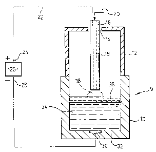
Figure 1 is a diagrammatic cross-section of a furnace
assembly for treating liquid metal;
Figure 2 is a graph of sulphur content of liquid metal
versus time for type 304L stainless steel;
Figure 3 is a graph of sulphur content of liquid metal
versus time for type 304-4~ C stainless steel, and
Figure 4 is a graph of (i) sulphur content of the
liquid metal versus time and (ii) sulphur content of the slag
versus time.
As can be seen in Figure 1, a furnace assembly 9
comprises a container 10 having a roof 12. An opening 14 in the
roof 12 is provided to receive an electrode 16 which extends
downwardly towards the container 10. This electrode has an axial
bore 18 extending through the centre thereof through which
plasma-supporting gas can be injected through inlet 20. This
electrode is connected by a wire 22 to the positive end 24 of a
DC power supply 26. The negative end 28 of the power supply is
connected to a cathode 30 at the base 32 of the container 10.
The operation of the apparatus illustrated in the
figure is as follows. Liquid metal 34 is introduced into the
1 337848
container 10 and a suitable compound is added thereto to form an
ionic melt layer 36 on the surface of the liquid metal. Power is
supplied to the system via the DC power supply 26. Gas is passed
axially through the electrode 16 to provide a plasma phase 38
above the ionic melt layer 36.
Variations can be made to the preferred embodiment of
the apparatus within the scope of the invention as described and
claimed. The electrode 16 could be a graphite electrode, a
plasma torch or any other type of electrode capable of sustaining
an electric arc or plasma. Preferably a graphite electrode of
the type disclosed in U.S. Patent 4,037,043, issued July 19,
1977,
is used. Alternatively, a plasma torch of the type disclosed in
U.S. Patent 3,749,802, issued 1973,
may be used. The container 10
can be electrically conducting, so that the cathode 30 i8 not
necessary to complete the circuit. Also, the roof 12 may be not
be necessary if ambient atmosphere and ambient pressure suffices
to provide the desired results. In some circumstances, such as
in desulphurization of liquid metal, the off gases should not be
allowed to escape lnto the atmosphere but rather into a ga~
collect~on system.
The invention will now be further described, by way of
illustration only, with reference to the following examples.
EXAMPLE 1
A furnace assembly similar to that of Figure 1 was
used. The furnace was lined with a 98% MgO ramming compound.
The inside diameter of the lined furnace was 11.4 cm and a
maximum heat size of 8 kg could be accommodated. A thyristor
invertor was used to provide 30 kw of power at a frequency range
of about 2500-4000 Hz to an induction coil located on the outside
of the container. The furnace roof was water-cooled and
ff.` '~
~ 0 r
-- 10 --
1 337848
constructed of austenitic stainless steel to minimize heating by
stray field from the induction coil. A 22 mm diameter graphite
electrode was admitted through a hole in the centre of the roof.
The electrode was insulated from the supporting structure by a
composite sleeve made of refractory paper and high temperature
silicon rubber. Clearance between the electrode and the sleeve
was about 0.5 mm to allow axial movement of the electrode. The
electrode was raised and lowered by a crank and gear arrangement.
A 6 mm axial hole was drilled through the length of the
electrode. The top end of the electrode was threaded to
accommodate a copper pipe gas inlet. The bottom was drilled out
and threaded to allow insertion of a consumable graphite
electrode tip. These tips are 100 mm long and 13 mm in diameter,
threaded at one end, with a 2 mm diameter hole drilled axially
therethrough. The electrode tips were replaced before they wear
down to within 10 mm of the electrode end. These small diameter
tips create a higher current density and thus better plasma
stability.
Plasma-forming gases, such as argon, were injected
through the hole in the electrode. The electrode was held by a
water-cooled aluminum clamp to which the electrical connection is
made. The return pass of the current was via a cathode
consisting of a 19 mm stainless steel pin protruding from a
water-cooled copper block embedded in a magnesia-chromate plastic
refractory at the base of the container.
A 15 cm diameter sealable port in the furnace roof
allows observation, alloying, slag addition, sampling and
temperature measurement. The furnace roof was mated to the body
of the furnace through a sand seal.
A DC power supply was used to provide the plasma
energy. The maximum current was 500 A and the open circuit
voltage is 75 V. Suitable plasma operation was possible from
1 337848
about 3.5 to 12 kW. The power delivered at a given setting was
virtually independent of electrode to slag layer spacing.
Rather, the voltage and current vary to compensate for the
changes in arc resistance. Thus an increase in the plasma length
results in a decreasing current and an increase in voltage with
any given power setting.
Arc voltages and currents were continuously monitored
during DC plasma operation. Voltage was measured directly across
the supply terminal, while current is measured indirectly by
voltage drop across a shunt resistor in the supply line.
Desulphurization studies using the above apparatus were
conducted with type 304L stainless steel and type 304 stainless
steel alloyed with 4~ C. The composition of these is given in
Table 1. Slag of the composition of Table 2 was added to the
steel. The melt size was 5 kg with 500 g of added slag. During
the process, pin samples were taken periodically with 3 mm I.D.
quartz tubes. The induction supply was momentarily set at a
r~A ~ mum power during sampling, in order to expose an area of
slag-free, convex melt surface. Taking samples from this area
minimized contamination of the pins.
TABLE 1
STEEL COMPOSITION
Steel Type Elements
Cr Ni Mn Si P Al Mo Cu Sn C Fe
Type 304L 18.5 10.1 1.11 .36 .028 .02 .22 .20 .01 .027 Balance
stainless steel
Type 304-4~ C 17.7 9.7 1.07 .35 .028 .02 .21 .19 .01 4.0 Balance
stainless steel
--- -- 12 --
1 337848
TABLE 2
SLAG COMPOS~TION
CaO Al23 MgO PeO P2o5 SiO2 S
46.6 46.6 1.9 O.9 .34 3.4 .22
With type 304L stainless steel, the electrode polarity
was negative for the first 73 minutes of application, then
positive for the duration of the experiment. The temperature was
1450C. As can be seen in Figure 2, the equilibrium sulphur
level was reduced from 180 ppm to 30 ppm upon switching the
electrode polarity to positive. Thus the use of a positive
polarity electrode increased the equilibrium sulphur removal from
the steel by a significant amount.
Type 304 stainless steel alloyed with 4% C was then
tested under the same conditions. For the first 42 minutes, a
negative polarity was applied and from 42-75 minutes after
starting, a positive polarity was applied. From 75 minutes on, a
negative polarity was re-applied. As can be seen in Figure 3,
the drop in sulphur content of the liquid metal is dramatically
increased when a positive polarity is applied.
Finally, the extent of sulphur removal was examined and
is shown in Figure 4. After 80 minutes, the sulphur content of
the steel is reduced to zero. The sulphur content of the slag is
also reduced to less than 0.01 wt % after 80 minutes.
EXAMPLE 2
The apparatus of Example 1, 5 kg of 304L stainless
steel and 500 g of the slag of Example 1 (see Table 2) were used.
The slag and metal were maintained at an average temperature of
1480C and a 5.5 kw positive polarity D.C. plasma was applied to
_ - 13 -
1 337848
the slag surface. After 140 minutes of treatment, the slag
composition was determined and is denoted as A in the following
table:
Slag CaO A123 MgO Cr23 FeO MnO SiO3 S
A 44.1 43.8 9.10 0.50 0.25 0.20 1.87 0.56
B 41.1 40.3 5.10 5.35 1.47 2.78 3.36 0.97
C 42.5 42.0 8.10 2.25 1.14 0.99 2.52 0.73
The polarity of the plasma was then reversed to negative, and a
further treatment of 135 minutes was carried out in this fashion.
The resulting slag composition was determined and is represented
by B. The increase of the oxides of iron, manganese, silicon and
chromium were noted, presumably oxidized from the melt. The
polarity was again reversed, so the applied plasma was positive.
After a further treatment of 65 minutes, the composition of the
slag was determined and is denoted by C. The decrease of the
fraction of reducible oxides was observed, notably oxides of
iron, manganese, silicon and chromium. The metallic components
of the oxides were alloyed into the steel by reduction at the
slag/metal interface.
EXAMPLE 3
The apparatus of Example 1 is used, and 5 kg of 304L
stainless steel and 500 g of slag of the above composition (see
Table 2) are used. 30 g of chromium oxide is added to the slag.
The slag is maintained at a temperature of 1480C and a positive
polarity of 10 kW DC plasma is applied to the slag surface. The
chromium dioxide migrates towards and is reduced to chromium at
the interface between the slag layer and the molten steel and
migrates into the molten steel to alloy the steel.
EXAMPLE 4
- 14 - I 337848
The apparatus of Example 1 is used, and 2 kg of iron
are used with 500 g of the slag of the above composition (see
Table 2). The slag and metal are maintained at an average
temperature of 1550C and a negative polarity of 10 kw D.C.
plasma is applied to the slag surface. 5 kg of an ore containing
30% NiO and 40% Cr2 03 iS added to the slag with enough carbon to
reduce the NiO. The amount of carbon used should be such that i)
significant amounts of the carbon are not solubilized in the
metal and ii) reduction of Cr2 03 does not occur. After
sufficient treatment time, the metal and slag phases are removed.
The metal phase is now ferronickel, and the slag phase contains
Cr2 03 . A further 2 kg of iron are melted in the furnace and the
slag phase previously removed is added back into the furnace.
An average temperature of 1550C is maintained and a positive
polarity of 10 kw D.C. plasma is applied to the slag surface.
Although not essential, the addition of some reductant such as
carbon can hasten the reduction of Cr2 03 from the slag phase, but
carbon is not added in an amount sufficient to carbonize the
metal excessively. A low carbon ferrochromium product can thus
be obtained. This sequential reduction procedure can thus
produce low carbon ferro-nickel and low carbon ferro-chromium
from the same ore in two steps.
EXAMPLE 5
The apparatus of Example 1 is used. An iron carbon
alloy is melted in the furnace and waste oxides comprising AOD
dust, electric furn-ace baghouse dust or similar wastes are added
continuously or intermittently to form a slag phase. 10 kw of
positive polarity D.C. plasma is then applied to the slag phase.
The oxides of iron, manganese, chromium and nickel are reduced
and the elements alloyed to the metal. The metal phase
accumulates as the reaction proceeds. The slag phase is fumed of
volatile impurities such as zinc, lead, cadmium and their oxides.
The resulting slag is non-toxic, non-leachable, and can be buried
as landfill. The resulting metal can be recycled to recover
- 15 - l 337848
valuable metallic units. The resulting fumes are collected in a
fume system and disposed of appropriately as is known in the art.
EXAMPLE 6
The apparatus of Example 1 is used. A copper or
copper alloy melt is used as the metal and a basic oxide slag
containing calcium fluoride is used as the ionic melt layer.
Some calcium may be present in the slag as dissolved metallic
calcium. A 10 kw positive polarity D.C. plasma is applied to the
surface of the slag layer. Group V impurities such as Bi, As, Sb
are reduced at the slag/metal interface, and combined with
metallic or ionic calcium to form components such as Ca3As2 or
ionic forms of these compounds. This is aided by the
polarization of the slag due to the applied D.C. polarity.
EXAMPLE 7
The apparatus of Example 1 is used. An impure nickel
melted from scrap nickel sources, such as used catalysts, is
used with an ionic melt layer comprising oxides. Purification to
remove oxygen and sulphur is carried out as in Example l for
steel.