Note: Descriptions are shown in the official language in which they were submitted.
-
- - 1 - 1 3 3 7 9 4 4
.~,T~n APPTTCATION
This is a divi~ion of Canadian patent application
serial no. 585,682 filed December 12, 1988.
BACKGROUND OF THE INVENTION
l. Field of the Invention
The present invention relates to an air bag and a
method of manufacturing the same. More particularly, the
present invention relates to an lmpact absorbing bag housed
in a center portion of a steering wheel which is capable of
sensing impact caused when a car collides with some object
and instantaneously inflating to ensure the safety of a
driver or the like and to a method for man~facturing the
impact absorbing bag.
2. Description of the Related Art
When a car collides with an oncoming car or
another object, the driver may smash his face strongly onto
the steering wheel or the front glass. If the impact
lS generated at that time can be reduced, it is possible to
prevent death or serious injury to the driver.
In many countries, drivers are obligated by law to
use seat belts as one means of safety upon collisions, but
the effective reduction of the impact by seat belts is not
sufficient when a car collides with an object at a high
speed.
Therefore, use of an air bag system, i.e., a
system capable of senslng an impact caused when a car
collides with an object and instantaneously inflating a bag
housed in a center portion of a steering wheel or the like
to ensure tne safety of the driver or the like is now being
considered in many countries as a more reliable safety
measure .
One conventional air bag has been manufact~lred by
forming a polymer layer on a plain woven fabric, providing
1 337944
-- 2 --
a gas introducing hole in one of the woven fabrics,
superimposing two woven fabri`cs with polymer layers in a
state with the polymer layer sides facing each other, and
sewing together circumferential edges of the two woven
fabrics. For example, Japanese Unexamined Patent Publication
(Kokai) No. 51-4742, in the portion explaining the
conventional air bags, describes that conventional air bags
are obtained by cutting two circular pieces of woven fabrics
from two regular square pieces of woven fabrics and sewing
together the circumferential edges of the two circular
pieces.
In air bags, a gas is instantaneously fed into the
bag by explosion of a pyrotechnic, so the air bag must have
a strength sufficient to endure the impact force caused by
the explosion. The above-mentioned method of manufacturing
air bags using a sewing process has several problems in this
regard. There are many manual working processes involved, so
there is a chance of de~reased strength of the sewn portions
and inspections of the strength of the sewn portions and the
air permeability of the woven fabric take much time. The
overall reliability of air bags manufactured by this method
is low.
A method of manufacturing air bags llsing a tubular
weaving method has been proposed. Japanese Examined Patent
Publication (Kokoku), corresponding to Japanese Unexamined
Patent Publication (Kokai) No. 57-58228, discloses an impact
absorbing tubular woven fabric having bag portions formed by
alternately folding two woven fabrics up and down at a
middle portion. In this tubular weave, a bag portion A and a
bag portion B having a connecting portion C, which consists
of the upper woven fabric and lower woven fabric woven
together in a jointed weave, are alternately provided. The
bag portion B is smaller than the bag portion A. The fact
1 337944
that this tublllar woven fabric could be coated was mentioned
in this patent publication, but a detailed explanation was
only qiven of a continuous body of an air bag.
Flrther, Japanese Examined Patent Publication
(Kokoku) No. 54-576, corresponding to Japanese Unexamined
Patent Publication (Kokai) No. 50-7232, di~closes an impact
absorbing bag having an upper connecting portion and a lower
connecting portion having weft threads with larger shrinkage
ratios than their warp threads. In the description of the
invention and the drawings of this publication, there was
shown an air bag having a square shape in plan view,
provided at the outer layer thereof with a covering layer.
However, when making separate bags from the impact
absorbing tubular woven fabric disclosed in Japanese
Examined Patent Publication (Kokoku) No. 57-58228, the above
tubular woven fabric should be cut along the widthwise
direction in a portion indicated as C in Fig. 9 in the
publication, so the shape of the cut fabric necessarily
becomes square. An air bag having a square shape has
problems such that the air pressure is not applied uniformly
over the air bag, the appearance of the air bag is inferior,
and it is difficult to neatly house the air bag in the
steering wheel. The impact absorbing bag disclosed in
Japanese Examined Patent Publication (Kokoku) No. 54-576
also has a square shape, so it has the same problems.
It is possible to make the chamber into which air
is blown an octagon by sewing the four corners of an air bag
of a square shape (in this case, the appearance of the air
bag is still square), but this sewn air bag has
disadvantages of the large cost of the labor to sew the
corners, the weaker strength of the sewn portions compared
to the other portions, and the lack of uniformity. Even if
this air bag is turned inside out by pulling the inside of
1 337944
the air bag through the opening at the center portion of the
air bag for the air insertion, only the appearance of the
air bag is improved. The other disadvantages, such as the
inferior uniformity, are not eliminated.
SUMMARY OF THE INVENTION
A first object of the present invention is to provide
an impact absorbing bag having superior uniformity,
appearance, and reliability and having the ability to be
easily manufactured.
A second object of the present invention is to provide
a preferable method of manufacturing the impact absorbing
bag having the above-mentioned characteristics.
An impact absorbing air bag in accordance with the
present invention consists of a seamless tubular woven
fabric constituted with a central zone, having substantially
a circular shape and formed by a non-connecting portion B2
of a tubular weave structure B, and a circumferential zone,
having a ring-like shape and formed by a connecting portion
Bl of the tubular weave structure B or by the connecting
portion Bl and a non-tlbular weave structllre A, wherein the
transition between the non-tubular weave structure A and the
tubular weave structure B is continuous. Further, at least
one portion of the s,lrface of the seamless t\lbular woven
fabric is provided with a polymer covering layer 2. A gas
introducing hole 3 is provided in the non-connecting portion
B2 of the tubular weave str~lcture B at one side of the
seamless tubular woven fabric 1.
Another type of impact absorbing bag in accordance with
the present invention is a bag having an inside-o~t
structure formed by pulling out the inside of the above-
mentioned impact absorbing bag through the gas introducing
hole.
The manufactlring method of the impact absorbing bag in
1 33794~
-- 5
accordance with the present invention consists of the
following steps, the order of which can be arbitrarily set:
a step of obtaining a continuous body of a seamless
tubular woven fabric by repeating a tubular weave strlcture
S B in which a plurality of warp threads are woven with a
plurality of weft threads in a manner that the more the weft
picking operation is repeated, first, the shorter the length
in the widthwise direction of the connecting portion Bl and,
then, the longer the length in the widthwise direction of
the connecting portion Bl, so that a non-connecting portion
B2 having a substantially circular shape is formed, or by
alternately repeating the above-described tublllar weave
structure B and a non-tubular weave structure A;
a step of forming a polymer layer on at least a portion
of a surface of the obtained continuous body or a segment
cut from the said continuous body;
a step of cutting the continuous body of the seamless
tubular woven fabric, or a segment cut from the continuous
body, in a circular shape to give a seamless t~bular woven
fabric constituted with a central zone, having substantially
a circ~lar shape and formed by a non-connecting portion B2
of a tubular weave structure B, and a circumferential zone,
having a ring-like shape and formed by a connecting portion
Bl of the tubular weave structure B or by the connecting
portion Bl and a non-tubular weave structure A, the
transition between the non-tubular weave structure A and the
tubular weave structure B being continuous, and
a step of providing a gas introducing hole in the non-
connecting portion B2 of the tubular weave structure B at
one side of the seamless tubular woven fabric.
Another manufacturing method of the impact absorbing
bag in accordance with the present invention f.lrther
includes a step of turning the impact absorbing bag inside
- 6 - I 3 3 7 9 4 4
out by pulling out an inner side of the impact absorbing bag
throlgh the gas introducing hole.
BRIEF DESCRIPTION OF THE DRAWINGS
Figure 1 is a plan view illustrating an example of a
continuous body of a seamless tubular woven fabric in
accordance with the present invention;
Fig. 2 is a front view illustrating the continuous body
illustrated in Fig. 1 and provided with a polymer layer;
Fig. 3 is a plan view illustrating an example of one
individual unit of the seamless tublllar woven fabric
provided with a gas introducing hole;
Fig. ~ is a cross-sectional view of an example of the
impact absorbing bag in accordance with the present
invention obtained by turning inside-out an individual unit
of the impact absorbing bag illustrated in Fig. 3 through
the gas introducing hole;
Fig. 5 is a cross-sectional view of another example of
the impact absorbing bag obtained by turning inside-out an
individual unit illustrated in Fig. 3 through the gas
introducing hole; and
Figs. 6 to 8 are plan views illustrating other examples
of the continuous bodies of the impact absorbing bag in
accordance with the present invention.
DESCRIPTION OF THE PREFERRED EMBODIMENTS
The present invention will now be described in detail
with reference to the accompanying drawings illustrating
embodiments.
As can be seen from Figs. 1 to 3, an impact absorbing
bag in accordance with the present invention uses as a base
woven fabric structllre a seamless tubular woven fabric 1
constitllted with a central zone, having a substantially
circular shape and formed by a non-connecting portion B2 of
a tubular weave portion B, and a circumferential zone,
_ 7 _ 1337944
having a ring-like shape and formed by a connecting portion
Bl of the tubular weave structure B or by the connecting
portion Bl and a non-tubular weave structure, in which the
transition between the non-tubular weave structure A and the
tubular weave structure B is continuous.
The seamless tubular woven fabric as described
herebefore can be obtained by preparing a continuous body of
the seamless tubular woven fabric manufactured by repeating
at least one tubular weave structure B in which a plurality
of warp threads~are woven with a plurality of weft threads
in a manner that the more the weft picking operation is
repeated, first, the shorter the length in the widthwise
direction of the connecting portion B and then the longer
the length in the widthwide direction of the connecting
portion Bl, thus forming a non-connecting portion B2 having
substantially a tubular shape, or by alternately repeating
the above-described tubular weave structure and a non-
tubular weave structure A, and then cutting the continuous
body of the seamless tubular woven fabric or a segment cut
from the continuous body in a substantially circular shape.
For example, first, the n~l~-tubllar weave structure A
is formed by repeating a non-tubular weave until the
predetermined length is obtained and then the tubular weave
structure B having the connecting portion Bl and the non-
connecting portion B2 of a substantially ring-like shape is
manufactured by performing a tubular weave operation, i.e.,
a warp and weft double weaving weave in which a front layer
and a back layer are connected to each other at both edge
portions, in such a manner that the more the weft picking
operation is repeated, first, the shorter the length in the
widthwise direction of the connecting portion Bl and then
the longer the length in the widthwise direction o~ the
connecting portion Bl. After that, a continuous body in
-- 8 --
1 337944
which a plurality of the seamless tubular woven fabrics are
aligned in a row, as illustrated in Fig. 1, can be obtained
by repeating th non-tubular weaving operation and the
tubular weaving operation gradually changing the length in
the widthwise direction of the connecting portion Bl at both
edge portions.
In this case, when a connecting portion Bl having some
width is further arranged on a middle portion in the
widthwise direction of the continuolls body, a continuolls
body can be obtained in which a plurality of the seamless
tubular woven fabrics are arranged in two rows as
illustrated in Fig. 6. A continuous body in which a
plurality of seamless tub~llar woven fabrics are arranged in
rows of three or more can be easily obtained in the same
manner as that of the previous case. Further, a continuous
body in which a plurality of seamless tubular woven fabrics
are arranged in a zigzag state as illustrated in Fig. 7 can
be obtained by repeating a required number of times only the
tubular weaving operation in which the length in the
widthwise direction of the connecting portion Bl at both
edge portions is gradually changed and not applying the non-
tubular weaving operation.
The weaving of the seamless tubular woven fabric can be
performed by using a dobby loom, a jacquard loom, or the
like.
The shape of the non-connecting portion B2 in the
tubular weave structure B is generally circular or nearly
circular, but it is possible to make a deformed circle as
illustrated in Fig. 8. The impact absorbing bag including
the non-connecting portion B2 of the deformed circle can be
usefully used as an air bag in the front passenger seat or
the rear passenger seats.
A plain weave, twill weave, satin weave, or the like
1 337944
g
can be used as the weave in the non-~onnecting portion and
the connecting portion.
As the weft thread and the warp thread used for
manufacturing the seamless tubular woven fabric, a thread
produced from a polyester fiber, polyamide fiber, including
aramide fibers, acrylic fiber, polyvinyl alcohol fiber,
polyvinylidene chloride fiber, polyolefin fiber,
polyurethane fiber, fluoroplastic fiber, semisynthetic
fiber, regenerated fiber, natural fiber, carbon fiber, glass
fiber, ceramic fiber, metal fiber, or the like can be used.
Further, a thread having a suitable elasti~ity can be used.
A polymer layer 2 is provided on at least one portion
of a surface of the seamless tub~lar woven fabric 1 to
prevent permeation of gases through the woven fabric 1.
Generally, the polymer layer 2 is provided on the entire
surface of both sides of the seamless tubular woven fabric,
but the polymer layer may also be provided on just the
surface of the side facing the driver when the air bag is
mounted in a steering wheel.
As examples of the polymer layer, mention may be made
of film produced from a polyurethane resin, polyester resin,
polyamide resin, polyvinylidene chloride resin, polyvinyl
chloride resin, polyolefin resin, fluorine resin, sili~one
resin, polystyrene resin, cellulose polymer, natural rubber,
synthetic rubber, or the like. A polymer capable of forming
an elastic film is useful. A polyurethane elastomer, a
polyester elastomer, a polyamide elastomer, a polyolefin
elastomer, or the like can be used as typical elastic
polymers. A polyurethane elastomer is particularly
preferable. Here, ~polyurethane elastomer" denotes a rubber-
like elastic polymer having a urethane radical in its
molecular structure and includes an adipate ester type, a
polyether type, a caprolactone type, and a polycarbonate
~ 337944
-- 10 --
type.
The polymer is generally applied ln a film state,
liquid state, solution state, dispersion state, or a molten
state on the outer surface of both sides of the seamless
tubular woven fabric and then is made into a laminate or
covering by heating, drying, cooling, irradiation by
activation energy, or the like.
Further, if necessary, it is possible to use a method
in which the warp thread and/or weft thread is previously
coated with the polymer, a fabric is made by the above warp
threads and weft threads,and the woven fabric is heated to
increase the flowability of the polymer on the surface of
the thread so that gaps in the woven fabric structure are
filled with the polymer.
The polymer layer 2 may be formed on the seamless
tubular woven fabric 1 for individual units of the fabric 1.
However, it is more efficient to form the polymer layer on a
continuo~ls body of the seamless tubular woven fabrics. It is
possible to apply the polymer layer to a segment cut from a
continuous body, for example, a segment including two
seamless tubular woven fabrics, a segment including three
seamless tubular woven fabrics, or a segment having the
shape of a square.
A gas introducing hole 3 is arranged on the tubular
weave structure B of the side of the seamless tubular woven
fabric with the polymer layer. The gas introducing holes
may be made in the continuous body, the segments, or the
individual Units.
To obtain the individual units of the seamless tublllar
woven fabric from the continuolls body, the connecting
portion Bl of the tubular weave stru~tllre B or the
connecting portion Bl and the non-tubular weave structure A
may be cut in a circular shape along a position slightly
_ 1 3 3 7 9 4 4
-- 11 --
apart from the circumferential edge of the non-connecting
portion B2 having a substantially circular shape in the
tubular weave structure B. It is advantageous to use melting
rather than me~hanical ~utting as a ~utting method. Thus,
individual units in~luding the non-connecting portion B2
having the circular shape of the tubular weave structure B
and a ring-like portion arranged circumferentially on the
non-connecting portion B2 and comprising the connecting
portion Bl or the connecting portion 81 and the non-tubular
weave structure A is obtained.
The polymer layer 2 is generally formed on the seamless
tubular woven fabric 1 from the outside of the fabric 1.
Therefore, the bag obtained by this method has a slightly
inferior feeling. Further, since the connecting portion Bl
of the tubular weave structure B or the connecting portion
Bl and the non-tubular weave structure A are present in a
circumferential portion of the bag, the appearance of the
bag is not always good. If the bag is turned inside-out by
pulling out the inside of the air bag through the gas
introducing hole 3, the feeling and the appearance of the
obtained air bag are remarkably improved. Therefore, it is
advantageous to use an inside-out air bag in terms of the
merchandiseability.
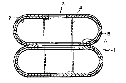
It is possible to provide one or more strands or strips
4 in~side the impact absorbing bag in accordance with the
present invention for limiting the inflation of the bag
between the front of the bag, as seen from the driver's
position, and the opposite side of the bag, as illustrated
clearly in Figs. 4 and 5.
The impact absorbing bag in accordan~e with the present
invention is housed in the central portion of the steering
wheel with the gas introducing hole 3 connected to a gas
generator. When an impact of a predetermined value or more,
- 12 - 1337944
for example, an impact generated when a car having a speed
of 16 km/hr or 25 km/hr collides head on with an object, is
sensed by a mechanical sensor or an electrical sensor, gas
generated by a pyrotechnic is suddenly fed into the bag, and
the bag is simultaneously inflated. For example, the bag is
inflated in 0.08 second after sensing of the impact. It is
also possible to feed a gas having a high pressure from a
gas cylinder. When the air bag is used for the front
passenger seat or rear passenger seats, portions capable of
housing the impact absorbing bags may be suitably arranged
inside the car.
The impact absorbing bag according to the present
invention uses as a base woven structure a seamless tubular
woven fabric constituted ~ith a central zone, having
substantially a circular shape and formed by a non-
connecting portion B2 of a tubular weave structure B, and a
circumferential zone, having a ring-like shape and formed by
a connecting portion Bl of the tubular weave structure B or
by the connectinq portion Bl and a non-tubular weave
structllre A, wherein the transition between the non-tubular
weave structure A and the tubular weave structure B is
continuous. Due to this, it is superior in terms of
uniformity, strength, and adjustment of the air-permeability
compared with the conventional method of forming a ba~ ~y
cutting out circular pieces of fabric from two square pieces
of fabric and sewing together the circumferences of the
same. Therefore, a high degree of reliability can be ensured
as an impact absorbing bag. Further the manufacturing steps
are streamlined and inspection time can be reduced, so it is
advantageous in terms of productivity as well.
Even compared with a square shaped air bag, seen in
plan view, prepared from a tubular weave, the impact
absorbing bag of the present invention is far superior in
-
- 13 - 1 337~44
terms of the overall uniformity of application of the alr
pressure, the external appearance, and the capability of
housing in a steering wheel.
The impact absorbing bag of the present invention,
housed in the center portion of the steering wheel, is
useful for the object of instantaneously inflation when
sensing an impact of collision of the car and ensuring
driver safety. It may be used not only for the object of
ensuring driver safety, but also for the object of ensuring
the safety of the passengers in the front passenger seat and
rear passenger seats.
The present invention will now be explained in further
detail by examples, which do not, however, limit the
invention in any way.
Example 1
Figures 1 to 4 show an example of the steps for
manufacturing an impact absorbing bag according to the
present invention.
Use was made of polyester multifilament yarn as the
warp and weft and weaving was performed using a jacquard
loom. First, non-tubular weaving was performed until a
predetermined width to form a non-tubular weave structure A,
then tubular weaving wherein the upper and lower layers are
joined only at the two edge portions was performed so that
the more the weft picking operation was repeated, first, the
shorter the length in the widthwise direction of a
connecting portion Bl and, then, the longer the length in
the widthwise direction of the connecting portion Bl, so
that a tubular weave structure B was formed. This non-
tubular weaving step to the tubular weaving step wherein thelength of the connecting portion Bl at the two edges was
changed was repeated.
By this, a continuous body of a single row of a
` - 14 - 1 337944
seamless tubular woven fabric 1 having a non-connecting
portion B2 of a tubular weave structure B which is
substantially circular in shape is obtained. (See Fig. 1.)
From the two sides of the continuous body of the
seamless tubular woven fabric 1 was coated a polyether
type polyurethane elastomer. This was heated to dry and
further cured to form a polymer covering layer 2. (See
Fig. 2.)
Next, separate circular pieces were cut by melting at
the connecting portion Bl of the tubular weave structure B
and the non-tubular weave strlcture A so as to give a diameter
somewhat larger than the circular non-connecting portion B2.
There was thus obtained a seamless tubular woven fabric 1
having a polymer covering layer 2 with a central zone,
having a circular shape, formed by a non-connecting portion
B2 of a tublllar weave structure B and a circumferential
zone, having a ring-like shape, formed by a connecting
portion B1 of the tubular weave str~ucture B. (See Fig. 3.)
Next, a hole was made in the center portion of the non-
connecting portion B2 on one side, along with the polymerlayer 2, to form the gas introducing hole 3 and thus
give an impact absorbing bag. (See Fig. 3.)
Further, this individual unit was turned inside out
from the gas introducing hole 3 to prepare the desired
impact absorbing bag. (See Fig. 4.)
Note that (4) in Fig. 4 is a strip for limiting the
inflation of the bag, which is provided according to need.
It is attached inside the bag between the top surface and
bottom s~lrface. This inflation limiting strip 4, as shown
in Fig. S, may be attached inside the bag between the top
surface and bottom s~lrface by tearing a portion of the top
s-lrf3ce and bottom surface of the bag, adhering the two ends
of the strip 4 so that they stick outside, then adhering a
- 15 - 1 337944
reinforcement piece 5 over the attached portion.
Example 2
Use was made of nylon multifilament yarn as the warp
and weft and weaving was performed using a dobby loom.
Except for this, the same procedure was followed as in
Example 1 so as to prepare a continuous body of a seamless
tubular woven fabric 1.
Next, a film of an adipate ester type polyurethane
elastomer was laid over the two surfaces of a continuous
body of the seamless tubular woven fabric 1. The composite
was passed between heating rollers for lamination, thereby
forming 3 polymer covering layer 2. A hole was made in the
center portion of the non-connecting portion B2 of the
tubular weave structure B on one side, along with the
lS polymer layer 2, to form the gas introducing hole 3.
Finally, this individual unit was turned inside out
from the gas introducing hole 3 to prepare the desired
impact absorbing bag.
Example 3
Figures 6 to 8 are plan views showing other examples of
the continuous body of the impact absorbing bag of the
present invention.
In Examples 1 and 2, a sinqle row of continuous bodies
of a seamless tubular woven fabric 1 was obtained and the
impact absorbing bag prepared from the same, but by
providing a connecting portion Bl at not only the two edges,
but also the width at the intermediate portion with the two
edges in the tublllar weaving step, it is possible to obtain
two rows of continuous bodies as shown in Fig. 6. It is also
possible to prepare impact absorbing bags similarly from
such two rows of continuous bodies.
The two rows of continuous bodies in Fig. 7 are
prepared by just repeating a necessary number of times j~lst
- 16 - 1337944
the step of tubular weaving wherein the length in the
widtnwi~se direction of the connecting portion ~1 at the two
edges is change.
The continuous body of Fig. 8 wa~ prepared by making
S the non-connecting portion Bl of the tubular weave structure
B a deformed circle ~n shape.