Note: Descriptions are shown in the official language in which they were submitted.
~ -1- 1 338534
METHOD AND SYSTEM FOR VARIABLE FREQUENCY
ELECTROMAGNETIC WATER TREATMENT
Backqround of the Invention
This invention relates generally to the treatment of
water or other liquids for the purpose of preventing
rust, and scaling of various liquid contacting
surfaces. More particularly, the invention provides an
electromagnetic water treatment method and system
whereby water is treated by an electromagnetic signal,
the frequency of which has been determined to provide
optimal absorption and/or emission of energy by the
particular atomic and molecular matter present in the
system.
The invention is particularly applicable where
inhibition or reversal of IUst or scale is desired.
Thus, the invention will be described herein with
specific reference to the inhibition or reversal of rust
and/or scale. It must be appreciated, however, that the
invention has broader utility and may be used in a
variety of applications including virtually any
application wherein electromagnetic energy is used to
bring about a reduction in biological/chemical o~ygen
demand; to alter the ionization or reactivity of other
X
-2- 1 338534
elements including but certairlly not limited to copper,
gold, carbon and platinum; to alter the
electromechanical characteristics of water or other
liquids; or to control the solubility of various
substances within water or liquids.
The prior art is replete with electromagnetic water
treatment methods and devices. Many such methods and
devices employ electromagnetic energy of fixed
frequency. Examples of such fixed frequency devices are
disclosed in United States Patent Nos. 4,659,479;
4,347,133; 4,Z28,323; 4,365,975; 4,582,629; 2,939,830;
4,151,090; 4,427,549; 4,407,719; and 3,715,305.
Several other United States patents disclose
specific methods and/or devices which employ varied
and/or mixed frequency electromagnetic energy. For
example, United States Patent No. 3,511,776 issued to
Avampato discloses a method of using various wave
lengths of electromagnetic energy, mostly within the
ultraviolet and x-ray spectra, to cause ionic species
within a flowing water system to become more susceptible
to attraction by a subsequent magnetic field.
United States Patent No. 3,625,884 issued to Waltrip
discloses a sewage treatment method which employs
multiple signal generators to simultaneously provide
audio frequency and/or radio frequency energy at a
number of different frequencies. The frequency output
of each separate signal generator may be selected on the
basis of the mineral content of the untreated sewage.
_ ~3~ 1 338534
~ United States Patent No. 4,365,975 issued to
Williams et al. discloses a method of recovering alkali
metal constituents from coal gasification residues by
subjecting the residues to electromagnetic energy in the
radiofrequency-microwave (0.1-105 MHz) range. Such
electromagnetic radiation is purported to facilitate
extraction of the metal.
Additionally, United States Patent No. 3,767,545
issued to Lucero discloses a device which uses
ultraviolet radiation to make certain ions more
susceptible to magnetic attraction. Lucero recognizes
that, theoretically, there exists a preferred wavelength
for each ion that is to be rendered more susceptible to
magnetic attraction. Lucero utilizes a separate magnet
and a vortex inducing apparatus to separate undesired
ions from a flowing water stream.
In general, the methods and devices of the prior art
utilize electromagentic energy to bring about various
effects on atomic or molecular matter contained in a
solution or suspension. One of the purported advantages
of many such prior art electromagnetic devices is that
they eliminate or reduce the need for the addition of
chemical water treatment agents. However, many of the
prior art methods and devices have proven to be only
minimally or sporadically effective in certain
applications. Additionally, the prior art devices and
methods are, in many cases, confounded by technical
complexity making such devices and methods expensive to~
manufacture and difficult to install.
~ 4 ` 1 338534
The present inven~on provides a versatile and
relatively simple method and system for employing
variable frequercy electromagnetic energy to treat
various liquids and to inhibit or reverse the formation
of rust or scaling of various liquid-contacting
surfaces. More fundamentally, the present invention
provides a method for determining the optimal
electromagnetic frequency to be employed in the
electromagnetic treatment of a liquid, such optimal
frequency being a function of the particular atomic
and/or molecular matter present in the treated fluid.
The method ~ the present invention may be employed to
qualitatively and/or quant;tatively alter the formation
of various chemical compounds within the fluid or on
fluid-cont~;ning surfaces.
In accordance with one aspect of the present
invention there is provided an electromagnetic
treatment method for a liquid contained in a system,
said method comprising the steps of;
a) generating an electromagnetic signal at a
frequency relating to the absorption/emission profile of
said liquid; and
b) directing said electromagnetic signal through
a non-insulated conductor into the liquid contained
within the system at a preselected location, said non-
-,, ,~
4a 1 3 3 8 5 3 4
insulated conductor being in electrical contact with
said liquid.
In accordance with another aspect of the
invention there is provided an electromagnetic treatment
system f or a liquid comprising:
means for generating an electromagnetic signal at
a preselected frequency related to the
absorption/emission profile of said liquid; and
means f or operatively connecting said generating
means to said liquid by a non-insulated conductor in
electrical contact with said liquid.
In the method electromagnetic signals of known
current intensity and varying frequency are initially
directed i nto - a fluidic system such as a water boiler,
hot water tank, industrial water system, or the like.
The current intensity of the signals may be subsequently
measured at a separate location some distance from the
J,
-5- 1 338534
initially delivered. As the signal frequency is varied,
the current intensity measured at the separate location
will typically vary above and below the known current
intensity of the signals. Such measured variations in
current intensity relative to the corresponding
variations in signal frequency provide a "profile~ of
the energy absorbing and/or emitting characteristics of
the particular atomic and molecular matter dissolved or
suspended within the liquid. The frequencies at which
maximal absorption and ma~imal emission are observed--or
any other selected frequency--may then be utilized,
solely or interchangeably, for subsequent
electromagnetic treatment of the liquid.
The relationship between current absorption and/or
emission and the frequency of the signal may be
.. ..
periodically redetermined. ~ased on such
redeterminations, adjustment~s) in treatment frequency
may be made during the course of the treatment period.
Such periodic optimization of the treating frequency
insures that the most effective anti-scaling effects
will be maintained during the ongoing treatment.
Initial test signals may be
generated by any type of variable frequency
electromagnetic generator capable of generating signals
within effective frequency ranges. A broad range (e.g.
O.1 RHz to lO00 MHz) is sufficient for water containing
systems in general. Signal generators having narrower
frequency ranges such as O.l KHz - lO0 MHz or 0.1
RHz-500 M~z may, of course, be employed, depending upon
5',' ,~
'' ~'f.r=:
-6- 1 338534
solute content of the liquid and the specific
application involved. The electromagnetic signals
utilized by the present invention are delivered by
way of probes which extend directly into the liquids, or
by way of attachment points located on liquid contacting
surfaces capable of transmittin~ the signal into the
liquids. In large installations such as industrial
boilers and the like, multiple probes or attachment
points may be utilized to insure that the signals are
uniformly transmitted throughout the entire installation.
The current intensity measurements may be
made by any current measuring device capable of
measuring within applicable ranges. The use of an
oscilloscope may be advantageous where visualization of
the waveform is desirable, however, a simple
.~ ,..
milliammeter will generally be an acceptable current
measuring device for the present invention.
Still in accordance with an alternate embodiment of
the present invention, the measuring device, whether it
be an oscilloscope, milliammeter, or other device, may
be omitted from the system. In such an embodiment, the
generator generates a signal at the approximate optimum
frequency for the desired effect or treatment of the
fluid. This type of operation may be conducted in
situations where a known frequency has been used in
other similar systems and omitting continuous
measurement, redetermination and readjustment of the
treatment frequency does not seriously reduce the
effectiveness of the system.
s B
~;,.
-7- 1 338534
The mechanism by which the present invention
functions is at least partially explainable on the basis
of the theory of quantum electrodynamics. In general,
quantum electrodynamic theory speaks to the manner in
which electromagnetic fields interact with atoms and
molecules, as well as the resultant interactions between
molecules. The theory of quantum electrodynamics is, in
part, based on the relation between the energy of a
quantum of light, the photon, and the frequency of any
electromagnetic field corresponding to it. In applying
quantum electrodynamics to the present invention, it
must be recognized that dynamic electromagnetic fields
are known to interact with the various charged particles
which form constituents of atoms and molecules (i.e.
electrons). As a result, the external application of an
electromagnetic field will bring about various
disruptions of the internal fields which are responsible
for the particular atomic or molecular structure and the
interrelationships of the charged particles therein.
Thus, depending upon the atomic or molecular matter
present, the energy absorption/emission characteristics
of a solution will vary as the frequency of the external
electromagnetic field is varied. By setting the
frequency of an externally applied electromagnetic
signal to maintain a specifically desired level of
absorption or emission within a solution or suspension,
the intended effects of the electromagnetic field may be
optimized.
Accordingly, a principal object of the present
invention is to provide a method and system for treating
liquid with an electromagnetic signal, the frequency of
which has been determined to correspond with a desired
-8- 1 338534
level of absorption or emission of energy by the
particular atomic and/or molecular matter contained in
the liquid. In most cases, the desired treatment
frequency will be the frequency at which maximum current
absorption is observed.
It is a further object of the present invention to
provide a method for optimizing the efficacy of various
electromagnetic liquid treatment devices by providing a
method for operating such devices at frequencies which
have been specifically determined to provide optimal
absorption or emission of energy by the particular
atomic and molecular matter contained within water or
other liquids being treated.
Another object of the present invention is to
provide a convenient method and system for utilizing
electromagnetic energy for the purpose of inhibiting the
formation of rust or scale on various fluid contacting
surfaces.
Yet another object of the present invention is to
provide a convenient method and system for altering,
reversing and/or removing existing rust, and/or scale
from fluid contacting surfaces.
A still further object of the present invention is
to provide a frequency-optimized electromagnetic liquid
treatment method which is effective to prevent, inhibit
or reverse the formation of rust and scale on liquid
contacting surfaces regardless of whether the liquid
remains static or is permitted to flow within the system.
1 338534
~ An additional object of the present invention is to
provide a system which may be used in an application
where the approximate frequency or effective frequency
for the given desired treatment is known and measuring
and adjustment are unnecessary.
Additional objects and advantages of the invention
will become apparent to those skilled in the art upon
consideration of the accompanying drawings and the
detailed description and examples which follow.
Brief Description of the Drawinqs
Figure 1 is a flow diagram outlining a preferred
method of the present invention.
Figure 2 is a schematic diagram of a preferred
system of the present invention.
Figure 3 is a diagramatic representation of the
experimental system described herein as Example 1.
Figure 9 is a diagramatic representation of the
experimental system described herein as Example 2.
Figure 5 is a diagramatic representation of the
experimental system described herein as Example 3.
Figure 6 is a diagramatic representaion of the
experimental system described herein as Example 4.
-lo- I 338534
-
Figure 7 is a diagramatic representation of the
experimental system described herein as Example 5.
S Detailed Description
Referring now to the drawings wherein the showings
are for purposes of illustrating preferred embodiments
of the invention and not for purposes of limiting the
same, Figure 1 outlines a preferred liquid treatment
method of the present invention in block diagram form
which, for purposes of explanation, comprises a water
treatment system. The initial step of providing varying
frequency test signals 10 may, depending upon the
frequency range desired, be accomplished by a variety of
devices capable of generating electromagnetic energy.
However, it is typically preferable to utilize a signal
generator capable of providing electromagnetic energy
within the radiofrequency band. Such frequency range is
generally sufficient to develop a usable
absorption/emission profile for most water systems. The
signal generating device is directly or indirectly
connected to the water being treated. The term
"absorption/emission" profile as used herein means a
visual or recorded summary of the absorption and
emission characteristics of the liquid being treated for
each of the test signals generated by the generator.
The second step of measuring current intensity at a
remote location 12 is accomplished by connecting any
appropriately calibrated current measuring device to a
point in the system where it will directly or indirectly
sense the current intensity of the signal within the
--10--
-- -11- 1 338534
water being treated. The water between the point at
which the test signals are provided 10, i.e. "signal
application point", and the remote location at which the
current intensity is measured, i.e. "current measurement
point", should be consistent and non-disrupted. Closed
valves or large air filled voids within the water may
disrupt the signal and result in distorted or erroneous
current intensity readings. The water between the
signal application point and the current measurement
point may be either standing or flowing, provided that
consistency, i.e. a steady state condition, is
maintained. Although any type of device capable of
measuring current intensity in the relevant range may be
used, the preferred embodiment employs an oscilloscope
whereby the waveform of the signal may be visualized and
additional waveform measurements may be made as
required. In many cases a simple milliammeter will be
an appropriate instrument for measuring current
intensity at the remote location 12. The current
measured at the remote location will vary as the
frequency of the test signal varies. Such current
variations relative to signal frequency are indicative
of absorption or emission of energy by the atomic and
molecular species present in the water. Thus, the
measured current intensity relative to the corresponding
test signal frequencies will generate an
absorption/emission profile 19. Such profile, in most
cases, will extend over a frequency range of
approximately 1 KHz to 100 MHz; however, any applicable
frequency range may be employed.
~ -12- 1 338534
After the absorption/emission profile has been
generated, the next step is to select a treatment
frequency 16. In most cases it is desirable to select
the frequency at which maximal absorption of current is
observed. Such is referred to as the maximal absorption
frequency. It should be appreciated, however, in
specific cases it may be desirable to select the
observed maximal emission frequency or any other
treatment frequency, the selection of which is made on
the basis of the previously generated
absorption/emission profile.
After selecting the treatment frequency, an
electromagnetic signal generator is set to provide a
treatment signal at the selected frequency 18. Usually,
a single variable frequency signal generator is used to
provide the test signals 10 as well as the subsequent
static frequency treatment signal 18.
After the water has been treated for a reasonable
period of time, the operator may optionally repeat steps
10 through 14, thereby periodically regenerating
absorption/emission profile data. If such newly
generated absorption/emission profile data indicates a
change in maximal absorytion or emission frequency has
occurred, the treatment frequency may be adjusted
correspondingly.
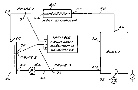
Figure 2 shows a schematic diagram of a preferred
embodiment wherein a system of the present invention is
used to treat an industrial boiler system. The system
comprises a condensate tank 40, a boiler 42, and a heat
-13- 1 338534
exchanger 94. A water line 46 fluidly connects outlet
port 48 of condensate tank 40 to the inlet port 50 of
boiler 42. A transfer pump 52 is positioned within
water line 46 for the purpose of pumping water from
condensate tank 40 into boiler 42. A steam line 54
connects the steam outlet port 56 of boiler 42 to the
inlet end 58 of coil-type heat exchanger 44. The steam
condenses within the heat exchanger and a condensate
line 60 carrying the condensate from the outlet end 62
of heat exchanger 44 to the inlet port 64 of condensate
tank 40. Thus, the subject boiler system comprises a
closed, continually recirculating hot water boiler
arrangement.
A variable frequency electromagnetic generator 70 is
connected to three separate signal output probes. A
first probe 72 located within condensate line 60, a
second probe 74 extends through the wall of condensate
tank 40 and a third probe 76 is located within water
line 46.
A milliammeter 78 is positioned so as to be in
operative contact with the water circulating into boiler
42 thereby providing a means of measuring the current
intensity of an electromagnetic signal emitted by
signals generator 70 and directed into the water by
probes 72, 74 and 76. Of course, an oscilloscope or any
other current measuring means may also be employed for
this purpose.
As the frequency of the electromagnetic signal
emitted by generator 70 is varied, the corresponding
-14- ~ 338534
absorption/emission profile may be determined on the
basis of the current measured by milliammeter 78
relative to the varied frequency of the electromagnetic
signal. By such method, a complete absorption/emission
profile for the system may be obtained and the signal
frequency which produces maximal absorption or emission
of energy may be determined.
A number of experiments were performed for thè
purpose of assessing and demonstrating the effects of
various embodiments of the present invention. The
particulars of several such experiments are set forth in
the following examples and the additional drawings which
correspond therewith.
Example 1:
Referring to Figure 3, two cut sections of heavily
scaled pipe, labeled A and B, were removed from a
h - commercial boiler. Plexiglass bottoms 100, 102 were bonded by silicone cement to one end of each pipe
section, thereby forming separate, open-topped
cylindrical containers having water-tight bottoms. A
spark plug 104 was tapped through the wall of container
A so as extend fully through the container wall. Both
containers A and B were filled with tap water. A 0 to
50 MHz variable frequency electromagnetic generator 106
was attached to the spark plug 104. An oscilloscope 108
was attached to the first pipe section at a second point
110 some distance from the spark plug. A plurality of
20 volt (peak to peak) electromagnetic signals of
~no-~s 7~Q~ m~J~
~ -15- 1 338534
~- varying fIequency were then directed into the spark plug
104 and the current intensity at the second point 110
was measured by oscilloscope 108 so as to discern the
absorption/emission profile of the water.
On the basis of such absorption/emission profile, it
was determined that the initial maximum absorption
frequency in water filled container A was 21 +/- 1 MHz.
Thereafter, the signal generator was set at 21 MHz and a
static 21 MHz signal was thereafter consistently
directed through spark plug 104.
The tap water in both vessels A and B was changed
every one or two days. Vessel A, into which the 21 +/-
1 MHz electromagnetic signal was directed, demonstrated
steady descaling at a rate of approximately 1~16 inch
per week while no descaling was observed in the
untreated pipe section. It is concluded that, in this
experiment, electromagnetic treatment at the initially
determined maximal absorption frequency was effective to
substantially reduce the thickness of previously
deposited scale.
Example 2:
Referring to Figure 4, the outlet port 140, a hot
water heater 142 was connected to one end of a 220 foot
long section of galvanized iron pipe 144. The opposite
end of pipe section 144 was connected to the inlet line~
148 of hot water heater 142. A recirculating pump 150
was positioned in line 144 so as to continually
recirculate water from the outlet 140 of water heater
-16- 1 338534
142, through the entire length of line 144 and again
into water heater 142 via inlet line 148. A spark plug
152 was tapped through a wall of the pipe at its
approximate midpoint and a variable frequency
electromagnetic signal generator 154 was attached to the
spark plug. A milliammeter 156 was attached to line 144
at a point some distance from the point at which spark
plug 152 was mounted. The system was filled with tap
water and pump 180 was activated. Electromagnetic
signals of varying frequency, ranging from 1 KHz to 100
MHz, were then directed through the spark plug 152 with
water continually circulating through the system. A
milliammeter 156 was utilized to determine the current
absorption/emission profile of the water. The maximum
absorption frequency was determined to be 28.5 MHz.
Thereafter, the signal generator 154 was set to generate
a signal at the previously determined maximum absorption
frequency of 28.5 MHz for a period of seven days during
which time the recirculating pump was continually run.
Quantities of make-up tap water, individually comprisiny
about ten percent of the system volume, were added to
the system each day through a water inlet valve 158
located in the inlet line 148 of the water heater 142.
Prior to the experiment, it had been determined that
visible scale of approximately 1/8 inch existed on the
inner surfaces of the hot water heater tank 142. After
seven days of frequency optimized treatment by the
present invention, the previously scaled water heater
surfaces were essentially clear of scale.
~ ~ -17- 1 338534
Example 3:
Referring to Figure 5, a section of galvanized pipe
200 having approximately 1/8 inch of scale deposited on
its inner surface was removed from an institutional
boiler system. The section of pipe 200 measured 12
inches in length and approximately 3/4 of an inch in
diameter. The removed pipe section 200 was suspended by
iron wire 202 from the top of a water filled iron
container 204 so as to be mostly immersed in the water
without contacting the sides of the container. A spark
plug 206 was tapped through one wall of the container
and a 0-500 MHz variable frequency signal generator 208
was attached to the spark plug. The signal generator
was powered by a 0-40 volt DC power source 210. The
power source 210 was grounded to the wall 212 of the
metal container.
Maximum absorption and emission frequencies were
determined by varying the frequency of signal generator
208 while measuring the current intensity of the signals
within the water using milliammeter 220. The maximum
absorption frequency was determined to be 40.5 MHz while
maximum emission was observed at 11.0 MHz. Treatment
was thereafter delivered, alternating from day to day
between such previously determined maximum absorption
frequency and ma~imum emission frequency. After nine
days of such alternating maximum absorption/maximum
emission treatment, the scale which had been observed on
the inner surface of pipe 200 was no longer present.
~ -18- 1 338534
Example 4:
Referring to Figure 6, two open containers C and D
were joined by a section of galvanized 3/4-inch pipe 250
running through the wall of each container C and D near
the upper rim thereof. The containers C and D were
filled with tap water such that the water level in each
container was above the respective inlet point of pipe
250. A separate polypropylene return line 252 was
positioned to connect containers C and D, fluidly
extending through the bottom of each container. A
recirculation pump 254 was positioned within
polypropylene return line 252 so as to continually
recirculate water from container C through the
polypropylene line 252 into container D and subsequently
out of the top of container D through the galvanized
connecting pipe 250 and again into container C.
A section of uncoated iron wire 256 was immersed in
the water contained in container C. Plexiglass lids
were bonded over the tops of containers C and D, thereby
providing a substantially water-tight, recirculating
system. The circulation of tap water within the system
was maintained at a rate of approximately 20 gallons per
minute by recirculation pump 254. Spark plugs 262, 264,
266 and 268 were tapped through various points in the
walls of pipe 250 and polypropylene return line 252 as
shown. A 0-50 MHz variable frequency electromagnetic
generator 270 was initially connected to spark plug 262.
With no signal generated, the wire 256 rusted and
turned a reddish-orange color in approximately three
-18-
`_ lg -` 1 338534
days. When a signal of 20.0 MHz was generated and
directed through spark plug 262 for a period of 24
hours, the rust disappeared and the wire appeared bare.
When the frequency was changed to 40.5 MHz for another
24 hours, the wire turned black with Fe304 deposits
and, following another 24 hours at 35 MHz the wire
exhibited red Fe304 deposits.
The experiment was thrice repeated, putting the same
frequency signals through each of the three remaining
spark plugs 264, 266 and 268 and the results in each
case were the same.
Example 5:
A separate experiment was designed to test the
continuity of the signal as it travels through a typical
industrial boiler system as outlined in Figure 7. A
water heater tank 300 having an outlet port 302 and an
inlet port 309 was connected to approximately 200 feet
of galvanized one inch steel pipe 306 such that the pipe
306 would extend between the outlet port 302 and the
inlet port 304 of tank 300. A transfer pump 308 was
positioned within line 306 to provide for a continual
recirculation of water from the tank 300 through the
pipe 306 and back into tank 300. A valved drain port
310 was also located at the base of pipe 306 and two-way
valves 312 and 314 were positioned at opposite ends of
pipe 306.
--19--
-20- 1 338534
-
The boiler 350 included a water inlet 352 and a
steam outlet 354. Steam line 356 was connected to the
steam outlet 354 of boiler 350 and through a coil-type
condcnser 358. The outlet end of condenser 358 was
connected to a condensate line 360. The condensate line
360 was connected to line 306 by way of a "T"
connection. A two-way valve 362 was positioned in line
360 to permit control of the condensate flow through
line 360 into pipe 306. A first spark plug 380 was
tapped through the wall of pipe 306, while a second
spark plug 382 was tapped into the water containing tank
portion of boiler 350.
A two channel electromagnetic generator 384 was
operatively connected to spark plugs 380 and 382. A
first signal (signal A) was emitted by channel 1 of
generator 389 and was directed through spark plug 380,
while a second signal (signal B) was emitted through
channel 2 of generator 384 and directed through spark
plug 382. A first oscilloscope 386 was connected to the
approximate mid-point of steam line 356, while a second
oscilloscope 388 was connected to the cold water inlet
290 of water tank 300. The water tank 300 and water
line 306 were consistently filled with recirculating
water. Thus, signal A is input directly via spark plug
380 into the water flowing through pipe 306.
Signal A was received and displayed by scope A with
no change in frequency, however, a diminution in
amplitude ranging from 10% and 100% was observed. Such
dimunution in amplitude was frequency dependent. At
frequencies of 107 M~z and above signal A, as
monitored
-20-
-21- 1 338534
-
by scope A, lost little signal power and no frequency
change was observed, provided that the water in tank 300
and line 306 remained constant and va]ves 312 and 314
remained open to permit continual recirculation of water
throuqh water heater 300 and line 306.
Signal B, emitted through spark plug 382 positioned
in boiler 350 was measured by scope B to determine the
continuity and consistency of signal B as it was
transmitted through boiler 350 and the attendant steam
line 356 and/or the condensate line 360 and condenser
358. Signal B was received intermittently by scope B
when connected through the condensate lines and
condenser as shown 388. When, however, scope B was
connected to steam line 356, signal B was ~eceived
without interruption. An apploximate fifty percent
decrease in signal amplitude -- but no change in signal
frequency -- was observed in steam line 356.
Alternate Embodiment Example:
As noted above, the milliammeter, oscilloscope or
other current measuring device need not be used in
situations where known or otherwise consistent
conditions exist. For example, in commercial laundries,
boilers are used. A frequency of approximately 40 MHz
has proven to be useful for treatment of such boilers.
Therefore, rather than incorporating measurement and
adjustment devices, a 40 MHz signal can be used with
such boilers, thereby minimizing the cost and complexity
1~ ~
-22~ 338534
of the system. If desired, spot checking may be used to
ensure that no dramatic departures from desired
operational characteristics and results occur. This may
be done by placing a measuring device on the boiler as
described above and going through the measurement steps
previously outlined, or by taking samples of the liquid
being treated to a test facility to determine if
significant changes have affected the
absorption/emission profile.
FIGURE 2 adequately illustrates such a system, if,
for example, milliammeter 78 is eliminated. Again, one
or more probes 72, 74, 76 may also be used to direct the
energy into the liquid.
The system of the present invention may also be used
for shocking a system, e.g. a laundry boiler. By
repeatedly activating and de-activating the generator,
or by reversing the signal's polarity (or phase),
significant effects on descaling rates have been noted.
While the above-described drawings and examples have
been included for the purpose of illustrating specific
experiments and embodiments of the present invention,
those skilled in the art will certainly appreciate that
various changes, modifications and applications may be
made without departing from the spirit and scope of the
invention. For example, the inventive method and system
may be used with virtually any of the devices available
for treating fluids with electromagnetic energy.
Although the experiments described herein routinely
ernployed a simple probe or spark plug as a means of
-22-
-
-23- 1 338534
.
-
directing the desired electromagnetic frequency into theliquid, many other means of directing such energy into
the liquid may be utilized in conjunction with the
method and system of the present invention.
Accordingly, it is intended to include all such changes,
modifications and applications insofar as they come
within the scope of the appended claims or the
equivalents thereof.