Language selection

Search

Patent 1338925 Summary

Third-party information liability

Some of the information on this Web page has been provided by external sources. The Government of Canada is not responsible for the accuracy, reliability or currency of the information supplied by external sources. Users wishing to rely upon this information should consult directly with the source of the information. Content provided by external sources is not subject to official languages, privacy and accessibility requirements.

Claims and Abstract availability

Any discrepancies in the text and image of the Claims and Abstract are due to differing posting times. Text of the Claims and Abstract are posted:

  • At the time the application is open to public inspection;
  • At the time of issue of the patent (grant).
(12) Patent: (11) CA 1338925
(21) Application Number: 1338925
(54) English Title: PORTABLE PIPE-BENDING MINIMACHINE ABLE TO BE MANUALLY-OR MOTOR-CONTROLLED AND INCLUDING AN ENGAGING/AUTOMATIC DISENGAGING DEVICE
(54) French Title: MINI-CINTREUSE DE TUBES, MANUELLE OU MOTORISEE, AVEC DISPOSITIF DE PRISE AUTOMATIQUE
Status: Expired and beyond the Period of Reversal
Bibliographic Data
(51) International Patent Classification (IPC):
  • B21D 7/04 (2006.01)
  • B21D 7/06 (2006.01)
(72) Inventors :
  • CAPORUSSO, ALESSANDRO (Italy)
  • CAPORUSSO, MARIO (Italy)
(73) Owners :
  • C.M.L. COSTRUZIONI MECCANICHE LIRI S.R.L.
(71) Applicants :
  • C.M.L. COSTRUZIONI MECCANICHE LIRI S.R.L. (Italy)
(74) Agent: GOWLING WLG (CANADA) LLP
(74) Associate agent:
(45) Issued: 1997-02-25
(22) Filed Date: 1989-07-18
Availability of licence: N/A
Dedicated to the Public: N/A
(25) Language of filing: English

Patent Cooperation Treaty (PCT): No

(30) Application Priority Data:
Application No. Country/Territory Date
48207A/88 (Italy) 1988-07-19

Abstracts

English Abstract


A rotary race pulley matrix (16) and pad
countermatrix (24) pipe bending machine, with the
countermatrix (24) supported through a holder (24")
therefor swinging in the lie of rotation of the matrix
(16) on a support (20) in its turn pivoted (22) so as to
swing in the lie of the matrix (16) on mounting means
(11) that are stationary with respect to the machine
body (11) during the bending operation. The oscillation
of the countermatrix (24) and of its support (20) is
restricted in the sense of feed of a pipe (p) by a pair
of complementary ledges (26, 27) provided on the
countermatrix holder (24") and on the support (20) and
by a pair of complementary ledges (32, 25) provided on
the support (20) and on the mounting means (24")
therefor respectively, said ledges (26, 27; 32, 25)
stopping the countermatrix (24) and the support (20)
correspondingly to the working position of the
countermatrix (24).


Claims

Note: Claims are shown in the official language in which they were submitted.

- 5 -
CLAIMS;
1. A pipe bending machine comprising a rotary
race pulley matrix (16), a pad countermatrix (24) held
by a countermatrix holder (24") and a machine body (11),
characterized in that the countermatrix (24) is pivoted
(23) through its holder (24") rotateably in the lie of
rotation of the matrix (16) on a support (20) in its
turn pivoted (2 ) so as to swing in the lie of rotation
of the matrix (16) on mounting means (11) that are
stationary with respect to the machine body (11) during
the bending operation, the oscillation of the
countermatrix (24) and of said support (20) being
restricted in the sense of feed of a pipe (p) to be bent
between the matrix (16) and the countermatrix (24) by a
pair of complementary ledges (26, 27) provided on the
countermatrix holder (24") and on the support (20) and
by a pair of complementary ledges (32, 25) provided on
the support (20) and on the mounting means (11) therefor
respectively, said ledges (26, 27, 32, 25) stopping the
countermatrix (24) and the support (20) correspondingly
to the working position of the countermatrix (24).

Description

Note: Descriptions are shown in the official language in which they were submitted.


1 338925
A ROT~RY ~C~ PULL~ MAT~Ix AND PAD COUNTERM~TRIX P~P~
BENDING MACHINE WITH A MOVABLE SUPPORT FO~ THE
COU~TERMATRIX
The preRent in~ention relates to ~ rotary race
pulley matris ~nd pad countermatrix pipe bending
~ac~ine .
~ known that with ~uch a type of ~achines
a pipe must be removed perpendi~ularly ~o ~he lie o~
r~tation of the matrix after a bending operation.
Therefore, it i6 nece~ary to move the
countermatrix away from the matrix for a distance at
least e~ual to the tiametre of t,he pipe before remo~ing
this from the bending machine.
~ ariou~ eontrivance~ ha~e been ~ugge~ed in
order ~o ~horten the time for performing ~uch a task.
In certain pipe bending machine~ the
c~Unter~triY au~o~atically fall~ from the bendin~
machine at the end o~ a bending operation. With ~uch a
~achine, however, a worker has to pick up the fa1len
countermatrix and ~o rea~emble i~ to bend another pipe,
with a con~iderable waste of time and consequent
reduction of producti~i~y.
In other pipe bending machineæ t~e
countcrma~rix is a~embled on a support through a
coun~ermatrix holder, which can be a portion thereof or
a se~arate member. ~he ~upport i8 movable on a rack or a
RcreW to bring it to the right posi~ioning with respec~
to the matrix and fix it in correspondence thereof.
Thus~ it i8 po8~ible to di~pl~ce the 6upport away from
the matrix on the rack or ~crew and remove the pipe.
Howe~er, thi~ al~o i~ a con~iderably time-c~nc~ming

1 338925
- 2 -
oper~tion.
Still in other pipe bending machines the
countermatrix wit~ it~ holder i~ as~embled on a support
~ich i~ pivotedly mounted on the body of the mac~ine 80
~h-t one i8 able to rotate i~ away from the ~atrix and
re~ove the pipe after ~ bend~ng operation. Howe~er, this
8till turns out to be a considerably time con~uming
operation.
It iR therefore felt the need for a pipe
b~n~i ng oachine wherein the operation o~ removal of a
bent pipe therefrom c~n be per~ormed more quickly than
in tho~e available heretofore, in order to ~ubstantiall~
increa~e the ~-- ~c. o~ pipes that a worker is abl~ to
bcnd in a unit of time.
The object of the pre~ent inven~ion is to
sati~fy ~uch a need.
This object i~ achieved by mean~ of the p.ipe
bendine ~achine accordine to claim ~. It ~as th~
counterma~ris pivoted throu~h it~ holder rotateably in
the lie o~ rotation of the matrix on a support in it~
turn pivoted ~o a~ to swing in the lie o~ rotation ~f
the ~atrix on ~ountin~ mean~ that are stationary with
re6pect to the machine body d~ring the bending
operation. The oscillation of the countermatrix and of
~aid ~upport i~ re~tricted in the ~en~e of feed of a
pipe to be bent between the matrix and the countermatrix
bg a pair of complementary ledge~ provided on the
countermatrix holder and on the BUpport and by a pair of
complementary led~es provided on the ~upport and ~n ~he
mounting mean~ therefor respectively, ~aid ledges
~topping the counter~a~rix and the ~upport
corre~pondingly to the working po~ition of the

1 33~
- 3 -
counter~atrix.
The advantage offered by the pre~en~ invention
iR that when the operation of bendin~ a pipc i~ cndcd,
~he countermatrix automatically re~o~e8 it~elf from the
matrix, allowing ~he pipe to be i~mediately removed from
the b~n~i ~e ~achine. Such an automati~m allow~ a
conQiderable incre~e of productivity to be achieved.
The present invention will be better
under~tood in the li~ht of the followin~ detai~ed
description o its preferred embodiment, given only aR a
matter of example and not of limitation, with reference
to the annexed drawings, w~erein:
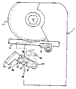
- figure 1 is a schematic ~op view of a pipe
bending machine according to the pr~ent in~ention, and
- ~igure 2 i~ a side view of ~he ~upport of
the countermatrix thereof.
The pipe bending mach~ne hac a machine body
generally rcferred to with the numera~ 11. On the body
11 a ben~ing head i~ arranged, compriQing a rotary race
pulley ~atrix 16, driv~n by a ~haf~ 15, a ~houlder 19
and a pad counter~atrix 24. The la~ter include~ a holder
portion 24" for it~ a~Re~bly on a ~upp~rt.
The ~upport of ~he countermatrix i~ generally
referred to with the numeral 20. As can be seen ~ith
reference to f~gurc~ 1 and 2, it consist~ of a "C" piece
with t~o flat parallel ~rms 21, 21', ~upporte~ by an
upri~ht pivoted 22 on the mschine body 11
perpendicularly to ~he arm~ 21, 21' and in the lie of
r~tation of the matrix 16. The space between the inner
parallel faces of the arms 21, 21' hou~e~ a p~rt of the
holder portion o~ the countermatrix that i~ endo~ed with
a hole for ~he pivoting on a pin 23, fitted between ~he
~. I

1 33B~25
-- 4
two ar~ 21, 21', for rotating in the lie of rotation of
the ~atrix 16. The countermatrix holder portion 24" i8
endo~ed with a nearly radial projection 26 at its
pi~oting portion, on the part op~o~ite th~ countermatrix
wi~h re~pect to the pi~ot 23. Such a projection 26
coopera~es with a ledge pin 27 arrane~d betwcen the arms
21, 21' 8~ as ~o limit ~he o~cillation of the
counterma~rix in the sen~e of feed of a pipe p between
the countermatrix itself and the matr~x. Therefore the
projcction 26 abuts on the pin 27 rotating in clockwi~e
direction. The rotati.on of the ~upport 20 is in it~ turn
re~tricted by a pin 25 provided on the machine body 11,
on which it abuts with a complementary reces~ 32
pro~ided on the lower arm 21'. T~e projection 26, the
pin 27, the rece88 32 and the pin 25 are 60 arranget, a~
~o stop t~c rotation of the couotermatrix and of the
~upport 20 eorrespondingly to the working position of
the coun~er~atrix, as repre~el~ted by dotted line~ in
figure 1.
The present invention has been dificlo~ed with
referencc to a specific embodiment thereof, but it is to
be underetood that change~, additions and/or omis~ions
can be made without departing from the ~cope of
pro~ection thereo~, which i~ defined b~ the enclosed
claims.
For example, the rota~eable ~upport o~ the
coun~ermatrix ha~ been described ~ directly arranged
upon the machine body, but it could al~o be arranged on
a slider f~ xable according to a set of di~tances from
the matriX ~n a rack, screw or the like.

Representative Drawing
A single figure which represents the drawing illustrating the invention.
Administrative Status

2024-08-01:As part of the Next Generation Patents (NGP) transition, the Canadian Patents Database (CPD) now contains a more detailed Event History, which replicates the Event Log of our new back-office solution.

Please note that "Inactive:" events refers to events no longer in use in our new back-office solution.

For a clearer understanding of the status of the application/patent presented on this page, the site Disclaimer , as well as the definitions for Patent , Event History , Maintenance Fee  and Payment History  should be consulted.

Event History

Description Date
Time Limit for Reversal Expired 2010-02-25
Letter Sent 2009-02-25
Inactive: Entity size changed 2005-03-10
Inactive: Payment - Insufficient fee 2005-03-10
Inactive: CPC assigned 1999-03-10
Grant by Issuance 1997-02-25

Abandonment History

There is no abandonment history.

Fee History

Fee Type Anniversary Year Due Date Paid Date
MF (category 1, 2nd anniv.) - small 1999-02-25 1998-12-23
MF (category 1, 3rd anniv.) - small 2000-02-25 2000-01-27
MF (category 1, 4th anniv.) - small 2001-02-26 2001-02-06
MF (category 1, 5th anniv.) - small 2002-02-25 2002-02-20
MF (category 1, 6th anniv.) - small 2003-02-25 2003-02-11
MF (category 1, 7th anniv.) - standard 2004-02-25 2004-02-11
MF (category 1, 8th anniv.) - standard 2005-02-25 2005-02-10
MF (category 1, 9th anniv.) - standard 2006-02-27 2006-02-06
MF (category 1, 10th anniv.) - standard 2007-02-26 2007-02-01
MF (category 1, 11th anniv.) - standard 2008-02-25 2008-02-21
Owners on Record

Note: Records showing the ownership history in alphabetical order.

Current Owners on Record
C.M.L. COSTRUZIONI MECCANICHE LIRI S.R.L.
Past Owners on Record
ALESSANDRO CAPORUSSO
MARIO CAPORUSSO
Past Owners that do not appear in the "Owners on Record" listing will appear in other documentation within the application.
Documents

To view selected files, please enter reCAPTCHA code :


To view images, click a link in the Document Description column. To download the documents, select one or more checkboxes in the first column and then click the "Download Selected in PDF format (Zip Archive)" or the "Download Selected as Single PDF" button.

List of published and non-published patent-specific documents on the CPD .

If you have any difficulty accessing content, you can call the Client Service Centre at 1-866-997-1936 or send them an e-mail at CIPO Client Service Centre.


Document
Description 
Date
(yyyy-mm-dd) 
Number of pages   Size of Image (KB) 
Representative drawing 2001-07-31 1 7
Cover Page 1997-02-19 1 18
Drawings 1997-02-19 1 15
Abstract 1997-02-19 1 29
Description 1997-02-19 4 140
Claims 1997-02-19 1 29
Maintenance Fee Notice 2009-04-08 1 170
Fees 2003-02-11 1 34
Fees 1998-12-23 1 33
Fees 2000-01-27 1 30
Fees 2002-02-20 1 33
Fees 2001-02-06 1 30
Fees 2004-02-11 1 35
Fees 2004-02-12 1 40
Fees 2005-02-10 1 31
Fees 2006-02-06 1 35
Fees 2007-02-01 1 30
Fees 2008-02-21 1 33
Courtesy - Office Letter 1989-11-02 1 72
PCT Correspondence 1996-04-15 1 26
Courtesy - Office Letter 1996-05-16 1 11
PCT Correspondence 1996-04-15 1 23
PCT Correspondence 1996-11-29 2 64
Prosecution correspondence 1993-02-12 1 36
Prosecution correspondence 1992-07-24 3 86
Examiner Requisition 1992-03-24 4 106
Examiner Requisition 1992-10-13 1 73