Note: Descriptions are shown in the official language in which they were submitted.
1 3~8932
Background of the Invention
The present invention relates to an automated in-
tegrated work station for handling goods within distribution
and production environments. In one of the preferred
embodiments the work station is specifically adapted for
consolidating goods.
Many modern distribution systems require the storage
and retrieval of thousands of inventoried goods. Often
goods must be stored in bins or containers due to their size
or delicate construction. Therefore, storage requires
loading the containers and delivering the containers to a
known location where they can later be retrieved as neces-
sary. When an order is received, the desired items must be
picked from their respective storage position and prepared
for either shipping or use. An effective warehousing
operation requires the ability to both rapidly retrieve a
A-48436/PDF/SDB
~ , .
~ 338932
wide variety of goods from storage and to efficiently
dispose of the retrieved items. The present invention
relates generally to an automated work station for rapidly
and effectively disposing of retrieved items. The work
station disclosed may also be used to receive goods into the
storage system.
An example of an existing complex distribution and
storage application is the environment of an electronic
product manufacturing and/or repair facility wherein the
products built incorporate printed circuit boards. Such
warehousing applications may require storage of as many as
150,000 components, the vast majority of which would fit
into 6"x6"x18" compartments. In any given day as many as 5
to 10 thousand assorted components may be drawn from the
storage facility. In the environment of a repair facility,
there must also be an effective mechanism for storing
various items. The stored items may include working parts
associated with a malfunctioning part in the process of
being repaired and/or components that cannot be repaired
using parts in stock while the unavailable parts are on
order. Absent effected integration between the storage
system and the work stations of the repair or manufacturing
facilities, the combined man hours lost between delivering
the goods to the appropriate work station and the down time
at various work stations as they wait for supplies to be
delivered would make the facility cost prohibitive.
Another typical example of a complex distribution
operation is a consumer products and pharmaceutical ware-
housing facility which stores and arranges such products for
delivery to retail outlets. Modern consumer products
warehousing facilities may require the storage of on the
order of 25,000 stock items which must be stored in both
case lots and piece lots. The individual stock items may
range in size anywhere between l"xl"xl" to 36"x36"x18". A
representative warehouse may have on the order of 1000
customers with in the range of 400 to 800 customers placing
orders on any given day. The orders may call for as many as
A-48436/PDF/SDB -2-
1 338932
60,000 individual stock units and the actual number of items
requested for each particular stock unit may widely vary.
Additionally, it is desirable to package the ordered goods
for each customer in lots of related goods rather than
sending each customer a truckload randomly containing all of
the goods that particular customer requested. For example,
in the consumer products and pharmaceutical application
described, related families of products might include RX,
hair care products, cosmetics, etc. Consolidating the
orders in groups of related goods facilitates rapid re-
stocking at the retail store when the goods are ultimately
delivered. Often, the ordered goods are delivered in totes
designed specifically for the purpose of transportation
between the warehouse and the retail stores.
Yet another application wherein efficiently integrated
work centers are required is in the environment of a
production facility. Recent studies investigating product-
ivity and quality control have suggested that it is often
more efficient to allow an individual worker to assemble
whole products (or at least substantial components), rather
than using an extended production line wherein each employee
adds only one or two small parts to a larger system. A
drawback to such systems is that in order to effectively
allow a single assembler to put together a product having a
large number of parts, it is important to "kit" the parts.
That is, they need to be arranged in readily accessible
groups, preferably in the reverse order of construction. In
many production lines, the kiting stage proves to be the
slowest link. Therefore, there is a need for a work center
that has access to all the parts and is capable of effec-
tively kiting parts for production requirements.
To facilitate these and other distribution applica-
tions, numerous integrated warehousing systems have hereto-
fore been proposed. Such systems traditionally include a
work station of some sort. For example, Japanese Patent
Application No. 53-37829 discloses a method for assorting
goods that are stored on fixed storage shelves. The system
A-48436/PDF/SDB -3-
1 338932
contemplates moving boxes containing ordered goods from a
storage shelf onto a horizontal loop-type conveyor which
transfers the boxes to a branch line wherein they are
reviewed by an operator. The operator looks at the goods in
the box and then identifies the customers who needs such
goods. He then drives a second loop-type conveyor to bring
a container before him into which the ordered goods may be
placed. However, such a system has significant time delays
in delivering goods to the operator. Further, the system is
not fully automated and the equipment provided is not
organized to maximize efficiency. Additionally, the
conveyors disclosed are horizontally oriented which requires
devoting abundant floor space to the material handling
operation. When the demands on the system change (tradi-
tionally volume tends to rise dramatically), the expansivefloor space required severely limits the ability to expand
the system to meet the increased demand without adding to
the size of the warehouse. It will be appreciated that the
increasing cost of space and the costs associated with
materials moving about an expansive area have become
significant drawbacks to such approaches. Thus, although
the systems heretofore available have greatly increased the
speed and effectiveness of material handling, they still
lack the ability to coordinate order consolidating activi-
ties fast enough to meet current demand in numerous applica-
tions.
Summary of the Invention
Accordingly, it is a primary objective of the present
invention to provide a new and improved work station for use
in conjunction with warehousing, production and repair
facilities for handling the disposition of items in great
quantity and variety wherein required manual operations are
minimized.
Another object of the invention is to provide a work
station having temporary storage facilities for queuing
inventoried items for random delivery to a work area.
A-48436/PDF/SDB -4-
1 3J8~3J
The lnvention provldes an automated work statlon for
use ln materlal handllng operatlons lncludlng a conveyor
network for carrylng contalners, sald work statlon comprlslng:
a randomly accesslble vertlcally movlng storage queue havlng a
multlpllcity of vertlcally spaced shelves arranged about an
endless loop for temporarlly holdlng sald contalners, drlve
means for rotatlng the shelves about the endless loop and
means for malntalnlng sald contalners on sald shelves; loadlng
means for recelvlng contalners from sald conveyor network and
for loadlng recelved contalners onto shelves of sald storage
queue; a plurallty of slde-by-slde work tables accesslble by
an operator for provldlng the operator access to the
contalners to selectlvely add or withdraw artlcles from sald
contalners; dellvery means for transferrlng selected
contalners from sald storage queue to sald work tables;
takeaway means for transferrlng contalners from sald work
tables to sald conveyor network; and control means for
automatically controlllng the dellvery of contalners between
said vertlcal queue and sald work tables.
The work statlon preferably ls sultable for
consolldatlng a wlde range of varlable orders uslng a mlnlmal
amount of manual labor, and for recelvlng goods lnto a storage
system uslng a mlnlmal amount of manual labor.
Preferably a flxed loadlng ramp ls provlded to load
contalners onto the vertlcal queue. To facllltate loadlng the
vertlcal queue, the shelves are rotated about the endless loop
untll an empty shelf ls dlsposed ad~acent the loadlng ramp
whereln loadlng may take place. To unload the vertlcal queue,
the shelf carrylng the contalner to be unloaded ls rotated
-- 5
si. 74260-25
~ 33~l322
until lt is disposed ad~acent the delivery means at which time
the container may be discharged onto the delivery system for
transportatlon to the work area. In a preferred embodiment,
the work area takes the form of a plurallty of rotatable work
tables.
- 5a -
- 74260-25
,
1 33~932
In another preferred embodiment, the work center is
designed to facilitate consolidating an extremely large
number of customer orders. In this embodiment a rotational
consolidation queue is provided that carries a large number
of totes suitable for receiving individual consolidated
orders. The consolidation queue is disposed in close
proximity to the work area so that an operator may readily
transfer goods between the work area and the consolidation
queue. The consolidation queue preferably includes a
multiplicity of vertically spaced shelf pans carried about a
track that forms an endless loop. Each shelf pan includes a
multiplicity of tote pads each adapted to hold one of the
totes. An opening mechanism, that may take the form of a
plurality of pneumatic rams, is provided to push particular
totes onto a fixed loading shelf to provide an operator with
access to the totes.
A preferred control system for the work station
includes a queue controller for directing movements of the
temporary storage queue and a conveyor controller for
managing the activities of the delivery and takeaway
systems. In embodiments having a plurality of work tables
and a consolidation queue, individual component controllers
in the form of a work table controller that manages the
activities of the work tables and a consolidation controller
that orchestrates movements of the consolidation queue would
be provided as well. A dedicated work center controller
integrates and manages the activities of the various
component controllers. Each of the component controllers
communicates with the work center controller and the other
component controllers over a primary local area network.
In a preferred architecture, a multiplicity of logic
boards are provided for directly controlling the mechanical
movements of the various components. Each of the component
controllers has a plurality of associated logic boards for
directly controlling the mechanical movements of the
particular component controlled by the associated component
A-48436/PDF/SDB -6-
1 338~32
controller. Each component controller has an associated
secondary local area network over which the component
controller communicates with its associated component
controllers. Preferably, each component controller further
has an associated interface board having a plurality of
buffers for receiving communications from the logic board
and temporarily storing the information transmitted by the
logic boards until the component controller requests the
transmitted information.
In a preferred method of operation aspect of the
invention, the work station is used to consolidate customer
orders, production kits, or the like. In such a system, a
multiplicity of orders for material goods are received. The
control system automatically assigns particular totes to
receive specific ordered goods. Containers holding ordered
goods are then delivered to the work area. Goods disposed
within a container in the work area are selected for
distribution and the operator is informed of both the
selected goods and the location of an active container that
holds the selected goods. The consolidation queue is
rotated until a shelf holding at least one tote designated
to receive the selected goods is disposed adjacent the fixed
loading shelf. A tote designated to receive the selected
goods is then automatically opened and the operator is
informed of the quantity of the selected goods that are to
be placed into the open tote. The ordered number of the
selected goods are placed into the open tote which is then
closed. The tote opening and queue rotating steps are
repeated as necessary to distribute the selected goods. The
goods selecting, queue rotating and tote opening steps are
repeated as necessary to consolidate all of the ordered
items into the totes. Each time the all of the materials
selected for distribution within a particular container
have been distributed, the spent container is discharged
from the work area and, when appropriate, an additional
container that carries material goods to be distributed is
automatically delivered to the work area.
A-48436/PDF/SDB -7-
1 3~`~93~
In an additional preferred embodiment, a multiplicity
of containers are originally requested from an external
storage system for delivery to the work station. The
received containers are loaded onto the vertical queue for
temporary storage. When containers are discharged from a
particular work table within the work area, a container
request is made for the delivery of an additional designated
container to the work table that discharged a container.
Similarly, each time a container is transferred from the
temporary storage queue, a request is made for the delivery
of an additional container to the work station from the
external storage system. In an alternative method of
operation the work station is utilized as a receiving
station for accepting inventory items into a storage system.
Brief Description of the Drawings
The features of the present invention that are believed
to be novel are set forth with particularity in the appended
claims. The invention, together with further objects and
advantages thereof, may best be understood by reference to
the following description taken in conjunction with the
accompanying drawings in which:
FIGURE 1 is a diagrammatic floor plan of a work station
having a pair of work areas supported by a single vertical
queue in accordance with the present invention.
FIGURE 2 is a diagrammatic floor plan of a simplified
warehousing system incorporating a work station in accor-
dance with the present invention.
FIGURE 3 is a diagrammatic side view of a typical
rotating work table as shown in Figure 1.
FIGURE 4 is a perspective view of a typical consolida-
tion queue as shown in Figure 1 with the front panel
removed.
A-48436/PDF/SDB -8-
~ 33893~
FIGURE 5 is a side view of a typical vertical queue as
shown in Figure 1 including the supporting frame and
highlighting the shelf guiding arrangement.
FIGURE 6 is a diagrammatic side view of the vertical
queue shown in Figure 5 with the frame and guiding channels
removed.
FIGURE 7 is a top view of a vertical queue shown in
Figure 5 with the frame removed.
FIGURE 8 is a top view of a vertical queue shelf taken
along line 8-8 in Figure 5 and including a soft stop
mechanism.
FIGURE 9 is a side view of the soft stop mechanism
shown in Figure 8.
FIGURE lOa is a side elevational view of a drive
assembly suitable for powering the vertical queue.
FIGURE lOb is a cross sectional view of the drive
assembly shown in Figure lOa taken along the line lOb-lOb.
FIGURE lla is a front elevational view of a weldment
attachment for the drive assembly shown in Figure 10.
20FIGURE llb is a side elevational view of the weldment
attachment shown in Figure lla.
FIGURE 12a is a side view of a portion of the drive
chain for the drive assembly as shown in Figure 10.
FIGURE 12b is a top view of the drive chain shown in
25Figure 12a.
FIGURE 13 is a side elevational view of the guide track
for the endless loop that comprises the vertical queue.
A-48436/PDF/SDB -9-
1 33~32
FIGURE 14 is a cross sectional view of the guide track
shown in Figure 13.
FIGURE 15 is an edge view of a portion of the guide
track shown in Figure 13 with the continuous loop in place.
FIGURE 16 is a cutaway front view of the guide roller
assembly for the compression chain.
FIGURE 17a is a front elevational view of a inner link
for the compression chain.
FIGURE 17b is a side elevational view of the inner
compression chain link shown in Figure 17a coupled to its
adjacent outer links.
FIGURE 18 is a time lapse diagrammatic view illustrat-
ing the travel of the weldment about the drive gear under
the influence of the guide channel.
FIGURE 19 is a time lapse diagrammatic view illustrat-
ing the travel of the weldment about the idler gear.
FIGURE 20 is a back elevational view of the guide
channel.
FIGURE 21 is a side elevational view of a flow through
power operated stopper assembly.
FIGURE 22 is a side view of the blocker assembly.
FIGURE 23 is a top view of the rotating work table
shown in Figure 3.
FIGURE 24 is a front view of one of the drive assembly
that raises and lowers the rotating work table platform.
FIGURE 25 is a side view of the coupling between the
A-48436/PDF/SDB -10-
1 338932
front edge of the work table base and its drive chain with
the sleeve and post partially cut away.
FIGURE 26 is a side view of the coupling between the
back edge of the work table base and its drive chain.
FIGURE 27 is a top view of the rotating work table
base.
FIGURE 28 is a top view of platform portion of the
rotating work table with the rollers removed.
FIGURE 29 is a top view of the geneva drive that
rotates the work table platform relative to its base.
FIGURE 30 is a side view of the geneva drive system
shown in Figure 29.
FIGURE 31 is a side view of the gate assembly for
retaining containers on the work table platform.
FIGURE 32 is a top view of the bottom shelf portion of
a consolidation queue pan.
FIGURE 33 is a cut away top view of the consolidation
queue taken at the level of the fixed loading shelf.
FIGURE 34 is a top view of a consolidation queue as
shown in Figure 33 with totes in place and highlighting the
extension of the multistage pneumatic rams.
FIGURE 35 is a side view of the self pan shown in
Figure 32.
FIGURE 36 is a front view of the consolidation queue
incorporating a conveyor stub for supplying empty totes.
FIGURE 37 is a plan view of an automatic tote loading
mechanism.
A-48436/PDF/SDB -11-
1 33a932
FIGURE 38 is a top plan view of a shipping and consoli-
dation queue arrangement.
FIGURE 39 is a perspective view of a suitable con-
tainer.
FIGURE 40 is a plan view of a receiving work station.
FIGURE 41 is a block diagram for representative work
center control system.
FIGURE 42 is a more detailed block diagram of a
particular work center controller as seen in Figure 40.
Detailed Description of a Preferred Embodiment
The automated work center of the present invention com-
prises a plurality of integrated components adapted to
facilitate high speed handling and distribution of bulk
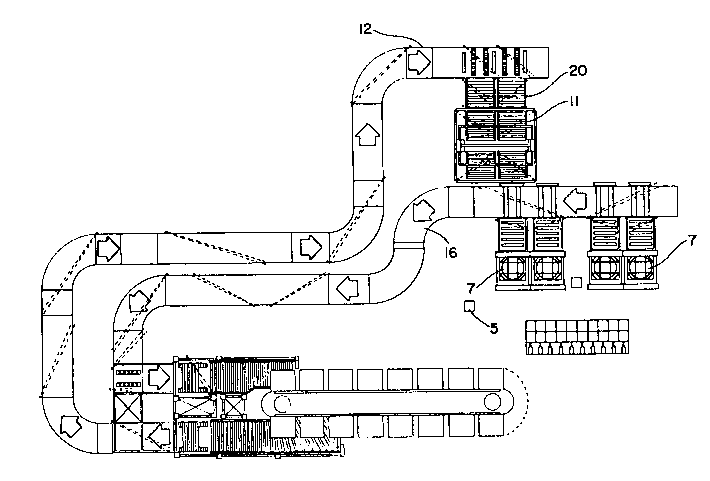
storage goods. Referring initially to Figure 1, an embodi-
ment of the work center chosen for the purpose of illustra-
tion includes two work areas 5 each having a plurality of
work tables 7, a temporary storage queue 9 that may take the
form of vertical queue 11, a supply conveyor 12, a delivery
system 14, a takeaway system 16, a control system 17 that
manages the activities of the work center and a consolida-
tion queue 18.
The work center is adapted to be integrated into a wide
variety of distribution, warehousing and production environ-
ments. In a simplified embodiment, the work center is
designed to substantially continuously provide an operator
with needed materials. In more sophisticated embodiments,
the work center may be integrated to assist an operator
consolidate customer orders or production kits or to receive
inventory into the facility. Alternatively the work center
may be configured to facilitate inspection, rewarehousing,
replenishment, inventory monitoring and/or production
assembly operations. To facilitate explanation, the system
A-48436/PDF/SDB -12-
1 33~32
74260-25
will be described in the environment of a consumer products
distribution system as discussed above. Referring next to Figure
2, in such a system, the inventoried items are kept in containers
stored in a remote storage structure 2. When a customer order is
received that requests a particular material good, the container
holding the requested goods is selectively picked from the storage
structure by an extraction assembly and delivered to the work
center via a suitable conveyor network 24. By way of example,
suitable storage structures are disclosed in United States Patent
No. 4,983,091, as well as in United States Patent Nos. 4,422,554
and 4,561,820. More conventional storage and retrieval systems
that utilize multi-level fixed storage shelves in combination with
an extractor picking mechanism may be used as well. The bulk
goods may be delivered to the work station in any suitable form.
For the purposes of illustration, the system will be described as
though the stored items are kept in containers 25 as described
below. It should, however, be understood that they may be
delivered on pallets, in boxes or in their original packaging
without departing the spirit of the invention.
The containers 25 are preferably open boxes that are
sized appropriately to receive the stored goods. A representative
container 25 is shown in Figure 39. The containers are preferably
square so that they may be delivered to the operator in any
orientation. The containers must be large enough to hold
reasonable quantities of the inventoried goods, yet they must be
small enough so that an operator can readily pick the goods
therefrom. By way of example, 36x36x24" containers are suitable
for most consumer product applications. In applications where
extremely small parts or small numbers of each item are
inventoried, smaller containers on the order of 24x24x16" would be
appropriate.
The containers 25 may be formed from a molded fiberglass
reinforced resin material. Each container has an identification
indicia 36 that individually identifies the
1 33893Z
particular container. By way of example, the containers may
be numbered sequentially with the numbers being applied in
bar coded form to each exterior corner of the container.
Bar code labels may be readily printed at the edge of the
container corners. It is desirable to label each corner to
enable a single scanner to identify the container regardless
of its orientation as it passes the scanner. With larger
containers it may also be desirable to control the orienta-
tion of the container when it is presented to an operator.
With such systems, the bar code labels are coded to indi-
vidually identify each particular corner.
In most warehousing operations, the sizes of the stored
goods will vary widely. Thus, for compatibility relatively
large containers are used so that only one or two container
sizes need be handled by the distribution system. To
minimize the empty shelf space, many of the containers would
be subdivided into multiple compartments 27 by placing wall
inserts 28 into the containers. Generally, there would be
containers having a wide range of compartment sizes within
the distribution or production system, with the actual
number of containers having a given compartment size and
being entirely dependent upon the nature of the goods being
stored. To maximize flexibility, wall inserts 28 may be
removable so that the number of compartments within any
container may be readily altered. To facilitate automatic
control, each compartment 27 has a specific designation
within the container 25. It is contemplated that each
container will have only compartments 27 of a uniform size
although it should be appreciated that this is not a
requirement.
Referring to Figure 1, a typical work center 1 includes
one or more work areas 5 having a plurality of work tables 7
adapted to receive the containers 25. A randomly accessible
temporary storage queue 9 preferably in the form of vertical
queue 11 serves as a holding point where the containers may
be temporarily stored before delivery to the work tables.
Thus, containers need not be supplied to the work tables 7
A-48436/PDF/SDB -14-
1 338932
in the same order that they are received by the work center.
The temporary storage serves the important function of
acting as a buffer for holding the next few containers that
will be required by the operator. Thus, when an operator is
prepared to receive the next working container, it may
readily be delivered to the work tables without experiencing
the delays likely to occur if the container was requested
from the storage structure. The actual construction of the
vertical queue 11 may vary widely within the scope of the
invention.
In operation, containers are carried to the work center
by an external conveyor network 24 that delivers containers
to supply conveyor 12. As containers enter the work center
they pass over supply conveyor 12 to any one of a plurality
of loading ramps 20 that feed vertical queue 11. When a
container is properly positioned on a loading ramp, the
vertical queue 11 is rotated until an empty shelf appears
adjacent the loading ramp. The container may then be loaded
onto the empty shelf. The vertical queue is randomly
accessible, therefore, when a particular container is
requested for delivery to the work area, the vertical
carousel is rotated until the requested container is
adjacent a discharge station 40 wherein it may be unloaded
from the vertical queue onto delivery system 14 for trans-
portation to one of the work tables. The work tablespresent the containers to an operator in a position such
that the operator may readily access the contents of the
container. After the operator is finished working with the
contents of the container, the container is discharged from
the work table to takeaway system 16 which returns the
container to the conveyor network for delivery either to
another work center or to the storage structure. In
embodiments wherein the containers are expected to be
relatively large, the work tables are preferably rotatable
so that the container may be presented to the operator in
any orientation. Specifically, the container is always
positioned such that the portion of the container that
A-48436/PDF/SDB -15-
1 33~93~
requires service will face the operator. This makes it
easier to access goods within the container.
The work center may be arranged to function as an issue
station that facilitates consolidation of customer orders,
production kits, and the like. Although the actual con-
struction of the issue station may vary a great deal within
the scope of the invention, as seen in Figure 1, each work
area within the described embodiment of the issue work
station contains a consolidations queue 18 adapted to hold a
large number of tote drawers 19. The consolidation queue
forms a vertically traveling carousel having a multiplicity
of shelves. Each shelf has a plurality of tote pads each
adapted to receive at least one tote 19. Using the consumer
products application previously described, the totes would
be designated to receive particular customer orders.
Throughout the rest of this disclosure, the system will be
described as though a single vertical queue 11 services a
single work area. However, it should be appreciated that a
single vertical queue could readily service two or more work
areas as shown in Figure 1.
When an order is received for goods found within the
warehousing system, the operator or an automatic controller
would request containers holding the desired goods from the
storage structure 2 as previously described. It will be
appreciated that a particular customer order may request
several different stock items. Thus, when the operator re-
ceives a container holding some of the ordered goods, he
would place those goods in a tote 19 associated with the
particular order. As the remaining goods are received, they
would be placed in the same tote drawer 19 until the order
is filled. Once the order has been filled, a shipping
invoice or production document is printed and placed into
the tote and the tote is dispatched to a shipping queue, a
packing station, an assembly station, a storage structure,
or the like, depending upon the requirements of the system.
A-48436/PDF/SDB -16-
1 338932
The totes 19 are preferably rectangular boxes having a
hinged cover. The totes must be sized such that they can
readily be manually moved about within the delivery trucks
and retail stores. By way of example, a suitable size is
16" x 22" x 10". Each tote has an identification indicia 37
that individually identifies the particular tote. The
identification indicia 37 may take the form of bar coded
labels. In alternative embodiments the totes may take the
form of cases of particular products.
VERTICAL OUEUE
Referring next to Figures 5-20, the embodiment of
vertical queue 11 chosen for the purpose of illustration,
will be described. As best seen in Figures 5-7, vertical
queue 11 comprises an endless progression of shelves 111
spaced about an opposing pair of endless loops 108 for
traveling around a frame 112. The endless loops may be
driven by an electrically or hydraulically operated motor
117. The opposite ends of shelf 111 are each attached to
one of the opposing endless loops by brackets 113 and
suspension struts 114, 115. As can be seen in Figures 6 and
8, each end of each shelf 111 has a pair of suspension
struts 114, 115 of appropriate length that are secured from
the front and back edges of the shelf respectively to the
corresponding brackets 113 by a pivot point 116 so that the
shelves are pivotably supported by the struts in a substan-
tially horizontal orientation. A support rod 120 which
extends the length of the shelf joins the suspension struts
to their corresponding bracket and therefore forms the
rotational axis of the pivot point. The pivotal mounting
causes the shelves 111 to always hang below the bracket and
support rod in a substantially horizontal orientation so
that the containers may ride with the shelf as the shelf
passes over from its up travel reach to its down travel
reach.
To ensure that the shelves remain substantially
horizontal when passing over the top and bottom ends of the
endless loop, top and bottom guide channels 121 and 122
A-48436/PDF/SDB -17-
1 3~8~
respectively are provided for each endless loop 108 to
cooperate with guide tubes 123 fixedly mounted on opposite
ends of the support rod 120. Each guide tube 123 carries a
roller 124 at its free end and a single guide tube 123
extends obliquely downward from each end of the support rod
120 in opposite directions relative to the vertical axis.
(Figure 8) As can be seen in Figures 5 and 20, the guide
channels 121, 122 define a semi-circular path equivalent to
the arc that the shelves must follow when passing between
the up travel reach and the down travel reach along the
endless loop, together with a pair of stub arms 125 that
define a portion of the up and down travel reaches of the
shelves. The channel portion 127 of the guide channels is
sized to closely receive the guide tube roller 124. The
open end of each stub arm 125 includes a substantially
trapezoidal funnel portion 126 that acts as a funnel
entrance to the channel portion 127 that ensures the rollers
124 will enter the channel portion as they begin to pass
over the top or bottom ends of the vertical queue. Since
the guide tubes 123 are fixed relative to the support rod
120, each guide tube 123 together with its roller 124 will
cooperate with the top and bottom guide channels 121, 122 to
ensure that its corresponding shelf will remain substantial-
ly horizontal as it passes over or under the queue by
pivoting about pivot point 116 as previously mentioned.
This action ensures that containers will not slip off of
their shelves as they pass over or under the queue.
Referring next to Figure 8, each shelf includes a frame
129 that supports a pair of side by side holding sections
130. Each end of the frame comprises a triangular support
formed by suspension struts 114 and 115 together with riser
131. A plurality of struts 132 extend between the opposing
risers 131. The holding sections 130 are formed of a
plurality of aligned low friction rollers 118 that extend
between riser members 133. The riser members are securely
fastened to struts 132 in a manner that allows low friction
roller 118 to freely rotate. To prevent containers from
floating around on the shelves, at least one of the rollers
A-48436/PDF/SDB -18-
1 338q32
118 takes the form of a ratchet roller that resists backward
movement of the containers.
In the embodiment used for the purpose of illustration,
movement onto and off of the shelves is gravity motivated.
Thus, the shelves are constructed so that each has a
permanent tilt. This may be seen in Figure 6 with the right
hand sides being slightly higher than the left hand sides.
Low friction rollers 118 on the shelves support the con-
tainers 25 in a potentially slidable condition. Shelf
blockers 119 hold the containers on the shelves until they
are ready to be released. With shelves arranged in this
fashion, containers are received on one side of the vertical
queue while they are be released on the opposite side.
As can best be seen with reference to Figure 8, the
suspension struts 114, 115 project slightly outwardly as
they extend riser 131 to support rod 120. The slant in the
suspension struts give the entire shelf a trapezoidal shape
that facilitates stacking. A pair of opposing guide members
depend from each of the risers to form a rounded V-shaped
guide that receives the support rod from the shelf disposed
immediately beneath it. The vertical spacing between the
shelves is adjusted such that when a shelf in on either the
up or down travel reach about its endless loop path, its
support rod will be closely held within the apex of the V-
shaped guide depending from the shelf positioned immediatelyabove, while its own guide closely receives the support rod
from the shelf disposed immediately below. This interlock-
ing of the shelves prevents the shelves from swinging back
and forth while they are outside the influence of guide
channels 121 & 122.
Since the containers may carry several hundred pounds
of materials and the loading ramp 20 that feeds the vertical
queue is gravity motivated, the containers may be traveling
with a great deal of momentum as they are loaded onto a
shelf. To reduce the impact with which the containers
strike the shelf blocker 119 during loading operations, a
A-48436/PDF/SDB -19-
i 338932
soft stop mechanism 136 is provided for absorbing a substan-
tial percentage of the containers momentum.
A soft stop mechanism 136 is mounted to the vertical
queue frame 112 adjacent each of the loading ramps 20.
Referring specifically to Figures 8 and 9, the soft stop
mechanism are disposed within the endless loop that defines
the travel of the shelves 111 and operates substantially as
a scissor type shock absorbing device. It includes a strike
bar 137 having a plurality of shock absorbing compressible
pads 138 thereon, a support rod 139, a pair of shock
absorbers 140 and 141 and a plurality of connecting members
142-144 for connecting the various components. Members 142
and 143 are pivotally coupled to each end of the strike bar
137. A first end of member 142 is pivotally coupled to the
strike bar and its opposing end is slidably coupled to a
slot 148 in frame element 149. Member 143 is substantially
L-shaped and is pivotally coupled to strike bar 137 on a
first end, shock absorber 140 on its opposite end and member
144 at its joint. Member 144 is pivotally mounted to the
support rod at an intermediate point while its ends are
pivotally mounted to the opposite end of shock absorber 140
and the joint portion of the L-shaped member 143 respec-
tively. Shock absorber 141 is connected to a similar
structure at the opposite end of the strike bar. Members
142 and 143 are identical for the opposite ends, while the
geometry of member 144 is varied between the two ends such
that the alignment of shock absorbers 140 and 141 are varied
as shown in Figures 8 & 9. Such an arrangement enhances the
shock absorbing characteristics of the soft stop 136.
It should be appreciated that the soft stop mechanism
must be fully withdrawn when the vertical queue is rotated
so that it does not interfere with the shelves. To facili-
tate fully withdrawing the soft stop, the shock absorbers
140 and 141 are both pneumatic cylinders that take a
collapsed position when they are not pressurized. When the
pneumatic shock absorbers 140,141 are in the collapsed
position, the entire soft stop mechanism rests inside of the
A-48436/PDF/SDB -20-
1 338~32
endless loop defined by the travel of shelves 111. When a
container positioned on loading ramp 20 is ready to be
loaded onto a properly positioned shelf 111, the pneumatic
shock absorbers 140,141 are pressurized thereby extending
the strike bar 137 to a position slightly upstream from the
shelf blocker 119. Thus, when the container 25 strikes the
soft stop mechanism 136, the shock absorbers dampen its
kinetic energy. The strike bar is then slowly retracted by
releasing pressure from the pneumatic shock absorbers
thereby allowing the container to position itself slowly
against the blocker 119. The weight of the container helps
compress the shock absorber as pressure is released.
Although the described embodiment of the loading ramp
20 and the shelves 111 incorporate are tilted to facilitate
gravity motivated loading and unloading, it should be appre-
ciated that equivalent mechanisms may be constructed that
eliminate the need for tilting by incorporating power
operated traction rollers or various actuators to transfer
the containers onto and off of level shelves on the vertical
lift. With such arrangements the need for a soft stop
mechanism as described above would be eliminated.
Referring next to Figures 10-17, the construction of
the drive mechanism will be described that is responsible
for rotating the shelves about the vertical queue in an
endless loop. To facilitate explanation, the entire drive
arrangement will be described as it applies to one side of
the vertical queue. However, it should be appreciated that
identical structures are provided on each side of the
vertical queue. Each endless loop 108 comprises a compres-
sion chain 150 formed of a multiplicity of pivotably coupledlinkage bars 151,lS3 that travel about a guide track 152.
The linkage bars (see Figure 17) alternate between inner
linkages 151 and outer linkages 153 that are pivotably
coupled together by an axle 154 disposed between a pair of
spaced apart equally sized tapered guide rollers 156. The
rollers 156 (as shown in Figure 16) are adapted to travel
about the guide track 152. The brackets 113 are fixedly
A-48436/PDF/SDB -21-
1 338932
mounted to the axle 154 by a mounting member that forms a
shoulder 155. Two brackets 113 are provided to support each
shelf. Only one bracket 113 is attached to each axle 154
and the brackets are arranged such that they combine with
one of the linkage bars to form a triangular support for the
shelf. As will be apparent from the description below, it
is important to the operation of the drive mechanism that
each linkage bar be the same length. Each of the inner
linkage bars is formed by a pair of spaced apart equally
sized plate members 157 coupled by a support element 149 and
a pair of tubular members 159 adapted to receive axle 154.
The outer linkage bars have apertures 148 adapted to align
with tubular members 159 to receive the axle 154 and form a
pivot point with the adjacent inner linkages. The outer
linkage bars also have supports similar to support elements
149 to increase the strength of the compression chain.
Referring specifically to Figures 13-15, the guide
track 152 is carried by a tower 158 which carries much of
the structural load of the vertical queue. The guide track
itself is formed of a pair of vertically extending track
portions 161 that are mounted to opposite sides of an I-
beam. Each track portion comprise a pair of spaced apart,
facing U-shaped members 160 adapted to receive the rollers
156. An opening is provided between the U-shaped members
160 that is wide enough to receive the linkage bars 151,153
and the bracket 113 and still leave enough room for the
drive weldments described below to access the shoulder 155
on axle 154. The top and bottom ends of the guide track are
left open so as to allow the linkage bars to rotate about
the ends without interference. It should be appreciated
that as the linkage bars rotate about the ends, their
associated shelves are being guided about the end by the
interaction between guide tube 123 and guide channels 121 or
122 as previously discussed.
To drive the compression chain in a continuous loop a
drive mechanism 170 is provided as will be described with
reference to Figures 10-12. The drive mechanisms 170 on
A-48436/PDF/SDB -22-
1 338 932
opposite sides of the vertical queue may be driven by a
common motor. Each drive mechanism is incorporated into a
removable unit that is attached between segments of the I-
beam. A pair of identically sized spaced apart endless
drive chains 171 each extend about a three gear set compris-
ing a drive gear 172, a spacing gear 173 that is sized
identically with the drive gear and a reduced sized idler
sprocket 174 as seen in Figure lOa. The two drive chains
and their associated gear trains are mirror images of one
another. Therefore, the drive mechanism will be described
by reference to a single drive chain 171 although it should
be appreciated that the described structure is duplicated in
actual practice. The drive gears 172 are carried by an axle
176 that is driven by motor 117.
The drive chains 171 are comprised of a plurality of
links 178 interspaced with a plurality of equally spaced
apart brackets 179. The brackets 179 carry a rod 180 that
extends between the two drive chains. Each rod is pivotally
coupled to a weldment attachment 182 by a tubular member 183
that is aligned perpendicularly with the plane of the
weldment 182. The weldments 182 are all identically sized
and it is important that they be equally spaced about the
drive chain. As can be seen by reference to Figure lla,
each weldment is symmetrical about its vertical axis and
includes a pair of opposing notches 185 adapted to engage
the shoulders 155 of axles 154 that couple the linkage bars
of the compression chain 150. The drive mechanism 170 is
positioned within the endless loop 108 such that the
weldment attachments may engage the underside of adjacent
endless loop axle shoulders 155. The drive mechanism
includes five weldment attachments dispersed about the drive
chains 171. The gears 172-174 are sized and spaced such
that at least one of the weldments will engage a linkage bar
on the up travel reach and at least one of the weldments
will engage a linkage bar on the down travel reach of the
endless loop at all times.
A-48436/PDF/SDB -23-
1 338~32
Referring next to Figures llc & lld, the orientation of
the weldments as they travel about the path of the drive
chain will be described. To facilitate a reversible drive
assembly, the weldments must be maintained in a substan-
tially vertical orientation as they travel about the loop
formed by drive chain 171. To maintain the weldments in the
upright position, a guide roller 186 is provided on the free
end of the weldment, and an alignment notch 187 is provided
on its bottom end. The guide roller is adapted to engage a
guide channel 189 disposed vertically above the drive
mechanism 170 when the bracket 179 that connects the
weldment to the drive chain engages the drive gear 172. The
contour of the guide channel 189 is arranged to ensure that
the weldment falls gently away from the link bar axle it
carries on an up travel reach as the weldment is rotated
about the end of drive gear 172. The guide channel 189 is
symmetrically shaped so that it serves to gently position
the weldment under a linkage bar axle on its down travel
reach as the weldment completes its journey about the drive
gear 172.
The alignment notch 187 works in combination with the
support notches 185 to perform the same function as the
weldment passes about the lower end of the drive mechanism.
As can be seen by reference to Figure lld, the weldment
begins to fall away from supporting engagement the link bar
axle it carries as it passes by spacing gear 173 on a down
travel reach. As the link bar is disengaged from the
support notch 185, the vertical surface 188 of the support
notch 185 rests against the link to prevent the weldment
from flopping loosely. As the weldment approaches the
idler sprocket 174 the alignment notch is engaged by an
alignment pin 184 positioned directly under the idler
sprocket 174. The geometry of the alignment notch and the
positioning of the alignment pin 184 are arranged such that
the weldment will flop to the opposite side such that it no
longer rests against a link bar on the down travel reach,
rather the vertical surface 188 of the opposite support
notch 185 rests against a link bar on its up travel reach.
A-48436/PDF/SDB -24-
1 338932
As the drive chain continues to rotate, the support notch in
contact with the link bar on an up travel reach is then
gently rotated into a supporting position underneath the
link bar.
Preferably the motor 117 is reversible so that the
shelves may be rotated in either a clockwise or a counter-
clockwise direction. With such an arrangement, when a
request is made for a particular container, the queue may be
rotated in the shortest direction to the release point. It
should be appreciated that the symmetrical guide channel and
alignment notch geometries described facilitate the use of a
reversible drive motor since changing directions of the
drive cable will not adversely affect the positioning of the
weldment.
A-48436/PDF/SDB -25-
1 33~932
SUPPLY CONVEYOR
Referring specifically to Figures 1 and 7, the supply
conveyor section 12 may be provided with one or more
transfer stops 90 for transferring containers from the
supply conveyor to an adjacent loading ramp. There are a
wide variety of conventional right angle transfer assemblies
for conveyors that may be used to form transfer stop 90. In
an embodiment of the transfer stop chosen for the purpose of
illustration, each transfer stop has a plurality of trans-
versely disposed traction rollers 92 mounted at longitudi-
nally spaced locations along the conveyor section 12 leaving
spaces 93 between the rollers. Power driven endless belts
95 which are disposed within the spaces 93 may be selective-
ly activated to divert containers onto the loading ramp 20.
A power operated alignment stop 97 is provided at the end of
each transfer stop to ensure that the containers to be
diverted to the adjacent loading ramp 20 are properly
positioned. Thus, when a container is delivered to a
particular transfer stop 90, its associated alignment stop
is raised and the container is carried by traction rollers
92 until it abuts against the alignment stop. A presence
detector 23 can be provided to detect the presence of a
container within the transfer stop. After the presence
detector verifies that the container is properly positioned,
the traction rollers may be turned off.
In the embodiment shown in the Figures, the loading
ramp is gravity motivated. With such an arrangement,
loading ramp 20 is tilted toward the vertical queue 11 and
is comprised of a plurality of transversely arranged low
friction rollers 162. A power operated stopper 164 which
may be pneumatically operated holds the containers until
they are ready to be loaded onto the vertical queue 11.
When the container 25 is loaded onto the vertical queue 11,
the queue is rotated until an empty shelf is positioned
adjacent the loading ramp 20 and momentarily stopped. The
power operated stopper 164 is released and the container
rolls freely over the low friction rollers 162 and 118 onto
the shelf until it strikes soft stop mechanism 136. Then,
A-48436/PDF/SDB -26-
~ ~J~39~2
as previously described, the container is gently lowered
into abutment against the shelf blocker 119. The soft stop
mechanism 136 will absorb much of the containers momentum as
previously described. Although in the embodiment shown in
Figure 5, loading ramp 20 is tilted to facilitate gravity
motivation, it should be appreciated that the loading ramp
can readily be adapted to facilitate substantially horizon-
tal insertion. This can be accomplished by replacing the
low friction rollers with power operated rollers or by
adding an actuator assembly capable of pushing containers
onto the vertical queue to perform the same function.
When a container 25 is to be unloaded from the vertical
queue, the queue is rotated until the appropriate shelf 111
is positioned adjacent the delivery system 14 and momen-
tarily stopped. The appropriate shelf blocker 119 isreleased, thereby releasing the container which due to the
tilt in the shelf 111 rolls freely across low friction
rollers 118 onto the discharge station 40 of delivery system
14. It should be appreciated that the shelves may be
substantially horizontal an outfitted with the traction
rollers to accomplish the same function. Conventional side
stopper arrangements are located on the side of the
discharge station opposite the exit points for the vertical
queue to insure that the discharged containers remain on the
delivery conveyor without damaging either the containers or
the conveyor. The discharge stations themselves may be
conventional right angle transfers that include three sets
of spaced apart roller wheels that are disposed between
traction rollers of the delivery conveyor. In such an
arrangement the conveyor for the delivery system is disposed
a few inches below the position at which the shelves are
stopped when they discharge the containers. The ends of the
roller sets closest to the vertical queue are tilted upward
when a container is to be discharged such that the end
substantially matches the level of the adjacent shelf edge,
thereby providing a smooth ramp for the container to flow
over when it is released.
A-48436/PDF/SDB -27-
1 338932
Referring next to Figure 21, a suitable construction
for power operated stopper 164 will be described. In
embodiments that incorporate the gravity motivated loading
ramp 20, the power operated stopper must act as a shock
absorber that absorbs the momentum of containers incident
thereon without bouncing the containers back towards the
transfer assembly. The power operated stopper includes a
pair of dogs 165 pivotally coupled to opposite ends of one
of the low friction rollers 162. A rubber strike roller 166
is rotatably coupled to the free end of dogs 155. A pair of
side by side hydraulic pistons 167 are coupled between each
dog and a fixed brace 168, as shown in Figure 21 such that
when the pistons are extended, the strike roller 166 is in
an upright position that block the container path. When the
hydraulic rams are withdrawn, the strike roller 166 is
pivoted into the plane of the low friction rollers 162 and
since it is rotatably mounted to the dog, the strike roller
functions as just another roller for the loading ramp. The
hydraulic pistons function as shock absorbers that receive
the impact of the containers as they slide down the loading
ramp.
Referring next to Figure 22, a suitable construction
for the shelf blockers 119 will be described. Since the
power operated blockers only need to be released when their
associated shelf is disposed adjacent the delivery system
14, the mechanism for actuating the blockers 119 may be
mounted in a single location on either the delivery system
or the vertical queue. A pnuematic piston (not shown)
activates push rod 280 when a container is to be released.
The push rod 280 is mounted to the vertical queue frame 112.
The blocker 119 includes member 282 which is pivotally
mounted to the the shelf riser 131 at its lower end. The
upper end of member 282 carries a low friction roller 284.
When a shelf is disposed adjacent the discharge station 40,
the push rod 280 may be activated. When activated, the push
rod 280 strikes the lower portion of member 282 thereby
causing the member 282 to pivot about a pivot point which
drops roller 284 from the raised position shown in Figure 22
A-48436/PDF/SDB -28-
9 ~ 2
to the lowered position shown in the same drawing. The
lowered position is in line with the other low friction
rollers 118 on shelf 111. A compression spring 285 is
mounted between the push rod 280 and a frame element 287
attached to frame 112. The compression spring returns the
push rod 280 to the contracted position when pressure is let
off of the pnuematic piston.
Similiarly, a return arm 291 is connected on a first
end to member 282 and on a second end to spring 293. The
opposite end of the spring is mounted to a bolt 295 in shelf
riser 131. Spring 293 is arranged to return the member 282
to the upright position when pressure is let off of the
pnuematic piston.
In the embodiment described for the purpose of illus-
tration, the vertical queue 11 is adapted to receive twoside-by-side containers on each shelf. The throughput of
the vertical queue can readily be varied by altering the
width of shelves 111 to accommodate various numbers of
containers on each shelf and providing the appropriate
numbers of loading ramps 20 and discharge stations 40. To
further increase the operational rate of the queue, multiple
vertically aligned loading and discharge systems may be
provided as well.
The delivery system is essentially a conveyor network
adapted to delivery the containers to an appropriate work
table. The delivery system 14 may include a supply stop 190
for each work table. The supply stops 190 may be con-
structed similarly to the transfer stops 90 or the right
angle transfers previously described. Each supply stop
retains a particular container until the loading ramp for
the work table 7 with which it is associated is ready to
accept that container. The construction of the loading
ramps for the work tables may be identical to the loading
ramps 20 previously described for the vertical queue.
ROTATABLE WORK TABLES
A-48436/PDF/SDB -29-
1 338932
The work tables 7 are adapted to automatically receive
and discharge containers and are positioned such that an
operator can readily access the contents within the con-
tainer 25 that is sitting thereon. As seen in Figure 3, the
embodiment of the work center described is arranged such
that the delivery conveyor of the delivery system 14 is
positioned directly above the takeaway conveyor of the
takeaway system 16. Thus the work table 7 is adapted to
received containers at one level and discharge containers at
a second level. However, it should be appreciated that the
positions at which the work tables receive and discharge
containers, as well as the actual construction of the work
tables 7 may be widely varied within the scope of the
present invention.
Referring next to Figures 3 and 23-31, the embodiment
of the work table chosen for the purpose of illustration
will be described. The work table 7 includes a frame 302
having two front posts 304 and two rear posts 306 that are
coupled by a plurality of frame members 303. The posts are
tubular and arranged in a rectangular fashion. The posts
are secured to the floor of the work area and frame members
303 extend between adjacent posts to provide the necessary
support. A rotatable platform 309 is carried by a substan-
tially rectangular base 310 that is slidably coupled to the
frame posts 304,306. A drive motor 312 carried by base 310
rotates the platforms 309 about a substantially vertical
axis. The base 310 is formed by a pair of parallel beams
311 that are coupled by a plurality of risers 313 (see
Figure 27). The beams 311 extend along opposite sides of
the frame 303 between one of the front posts 304 and a
corresponding rear post 306. Each corner of the base 310 is
connected to one of the posts by a sleeve 315. Each sleeve
315 is slideably coupled to an associated post and attached
to a drive chain 314 that may be selectively driven to raise
or lower the sleeve with respect to its corresponding post.
Referring next to Figure 24, each post has a drive
chain 314 arranged as a vertically extending endless loop
A-48436/PDF/SDB -30-
i 338932
between a drive sprocket 330 on its top end and an idler
gear 332 on the bottom. The drive chain 314 travels through
the tubular post on one of its reaches and outside the post
on its opposite reach (although for safety the portion of
the chain outside the operational traveling distance of the
platform may be protected by a shroud). The sleeves 315 are
each attached to the outer reach of their associated drive
chain. The drive sprockets 330 for the drive chains
associated with the front posts are mechanically coupled by
a drive bar 316. A similar drive bar couples the rear
sleeves in a similar fashion. The drives bars 334 are
driven by independent reversible motors 336. Thus, the
movements of the front sleeves are mechanically coupled, as
are the movements of the back sleeves. It will be appre-
ciated that the platform 309 may be raised by moving all
four of the sleeves simultaneously, or it may be tilted by
independently moving the front or rear sleeve pairs.
Referring next to Figures 25 and 26, the parallel beams
311 of base 310 are pivotally coupled between the front
posts 304 and the rear posts 306. As can be seen in Figure
25, the front ends of beams 311 are simply pivotally mounted
to their corresponding sleeves 315. In order to allow the
front and back sides of the platform to move independently,
a pair of lever arms 317 are provided to pivotably connect
the base to the rear post sleeves to provide the necessary
slack during tilting. As can be seen in Figure 26, a first
end of each lever arm is pivotably connected to one of the
beams 311 in base 310, while the second end of the lever arm
is pivotably connected to the associated rear sleeve. Thus,
the front and rear ends of base 310 can move independently
with lever arm 317 providing or absorbing the necessary
slack.
The platform 309 best seen in Figures 23 and 28 carries
a gate 321, a plurality of rollers 323, side rails 325 and a
pair of stoppers 327. The platform itself is substantially
square with the axis of rotation of rollers 323 extending
perpendicularly to side rails 325. In the embodiment chosen
A-48436/PDF/SDB -31-
1 338~32
for description, the delivery system 14 is disposed substan-
tially above the takeaway system 16. Thus, when a container
25 is delivered to the rotating work table the platform is
raised to the height of the delivery system. The gate 321
and a power operated stop 164 on the adjacent loading ramp
20 are both dropped and the container is guided by side
rails 325 as it passes over the rollers 323 until it is
stopped by the stopper 327. The gate 321 is then raised to
prevent the container from slipping off the platform. To
facilitate transferring the container from the loading ramp
20 to the platform 309, rollers 323 may be either power
operated or low friction. Low friction rollers are appro-
priate if loading ramp 20 is slightly inclined to provide
gravity motivation. With the gravity motivated system, the
first roller 324 may be a breaking roller to slow down the
container as it enters the work table platform. Alterna-
tively the braking roller may be provided as one of the last
rollers of the loading ramp to accomplish the same function.
Platform 309 is rotatably mounted to base 310 on a
circular track 340 carried by beams 311, 313 and a rotatable
shaft 341. See Figure 27. A plurality of rollers 360 are
mounted to the bottom side of platform 309 to travel about
the circular track 340. The circular track 340/rollers 360
arrangement is particularly useful for supporting unbalanced
loads, as will be frequently encountered with partially full
containers. A geneva drive system 342 driven by electrical
motor 312 rotates the platform as necessary. The geneva
drive (shown in Figures 29 ~ 30) is substantially conven-
tional and includes a square plate 344 having a roller 346
extending upward from each of its corners. The plate 344 is
mounted on the base 310, and is chosen to have four sides so
that each of the sides of the square containers can be
presented to the operator. The rollers 346 are designed to
engage channels 350 on the lower side of platform 309. As
can be seen in Figure 29, the channels 350 form a pair of
perpendicular lines that intersect at the axis of rotation
of the platform about shaft 352. The platform is properly
A-48436/PDF/SDB -32-
1 33~9~`2
positioned showing one of its sides when two of the rollers
346 engage their associated channels 350 as seen in Figure
29. It should be appreciated that such an arrangement
provides a great deal of stability in its fixed presentation
positions and that rotational movement between the presenta-
tion positions is sinusoidal. Each channel is formed by a
pair of parallel members 351. The plate 344 is driven by a
belt 348 that in turn is coupled to the drive shaft 349 of
motor 312.
Before a container can be placed on the work table, the
gate 321 must be dropped. A wide variety of conventional
mechanisms can be provided as the gate and the means for
raising and lowering the gate. A suitable construction is
shown in Figure 31. The gate 321 takes the form of an L-
shaped member that rests upon a moveable block 380. The
moveable block is coupled to the end of a extended rod 381
that passes through a couple of apertures 382 in the walls
of circular track 340. A hand operated lever 383 mounted
to the front side of base 310 is pivotally coupled to the
other end of rod 381. A compression spring 384 is biased to
press against the rod 381 to press the moveable block 380
towards the rear of the platform. When the work table is
sitting in a position such that the gate 321 is adjacent the
loading ramp, the handle 383 is disposed right in front of
the operator. To drop the gate, the operator pulls the
handle 383 which moves block 380 out from underneath the
gate member 321 thereby dropping the gate.
Once a container is placed on the work table, the
height of the platform is adjusted to suit the particular
operator and the platform is tilted towards the operator to
provide better access to the interior of the container.
Tilting is accomplished by raising the rear sleeves relative
to the front sleeves. To ensure operator comfort, it is
generally desirable to adjust the platform to approximately
waist height and tilt the table in the approximate range of
15-30 toward the operator. In a fully automated system,
when an operator is prepared to begin work, he logs into the
A-48436/PDF/SDB -33-
1 338932
controller which verifies that the operator is authorized to
work this station. The operators height may be inputted
into and remembered by the controller which can then vary
the level at which the containers are presented to the
operator to match the height of the particular operator.
Each work table is provided with a signal light 375 and
a pushbutton 370. The signal lights are controlled by the
system controller to light up over the active table. After
the operator is finished with an operation, he hits a
pushbutton 370 which informs the controller that the
designated task is complete. If other items within the
container are to be distributed or items are to be placed
in other compartments, the platform is rotated to the appro-
priate position. If the container will not be used any
more, the platform is rotated to its neutral positioned,
lowered to the level of the takeaway system 16 and tilted
such that the back side of the platform is lower than the
front. The gate 321 is then dropped and the container is
released. Again the container transfer may be accomplished
either through the use of power operated rollers or by
slightly inclining the platform towards the takeaway system.
CONSOLIDATION OUEUE
The consolidation queue 18 is positioned adjacent to
work area 5 such that an operator may conveniently work
between the consolidation queue and the work tables 7.
Structurally, the consolidation queue may take a form very
similar to the vertical queue 11, with the primary differ-
ences being in the loading and unloading mechanisms, the
shelf sizes and the containment mechanisms for keeping the
totes on the shelves. Referring next to Figures 4 & 32-38,
the embodiment of the consolidation queue chosen for the
purpose of this description comprises an endless progression
of horizontally oriented pans 410 spaced along an opposing
pair of endless loops 408 which may take the form of
compression chains, for travel about a frame 412. The
respective ends of pans 410 are attached to one of the
opposing compression chains by brackets and suspension
A-48436/PDF/SDB -34-
1 338932
struts just as the shelves of the vertical queue are
connected to their respective endless loops. Referring
primarily to Figures 32 & 35, each end of each pan 410 has
an associated pair of suspension struts 414, 415 of appro-
priate length that are secured from the front and back edgesof the pan to the corresponding bracket 413 by a pivot point
416 so that the pans 410 are pivotably supported by the
struts. The pivotal mounting causes the pans 410 to always
hang below the bracket and the pivot point in a substan-
tially horizontal orientation so that the totes 19 may ridewith the shelf as the shelf passes over from its up travel
reach to its down travel reach. The endless loop 408 may be
driven by an electrically, pneumatically or hydraulically
operated reversible motor 417. Thus, the consolidation
queue may be rotated in either direction.
Two shelves 411 are suspended from each bracket/-
suspension strut arrangement as can be seen in Figure 35.
It should be appreciated that in alternative embodiments,
the pans 410 may readily be constructed so that only one or
more than two shelves 411 are suspended from each bracket.
The two shelve construction is advantageous in the consumer
products distribution application described above because it
facilitates standardization of parts between the consolida-
tion queue and the vertical queue. The standardization is
possible since the totes are on the order of one-half the
height of the described containers which allows many common
components between the two queues.
Each shelf includes a riser 421 on each end of the
shelf that is secured between suspension struts 414, 415 to
provide a triangular frame that supports the shelf. (Figure
32). A plurality of struts 422 extend between opposing
risers 421 to form the base of the tote pads 419. The upper
sides of struts 422 are rounded to provide a low friction
surface over which the totes may readily pass.
Shelves 411 are sized and arranged so that the plu-
rality of tote 19 may be placed side-by-side on each shelf.
A-48436/PDF/SDB -35-
1 338932
Preferably, each shelf includes a plurality of tote pads
419, each of which receives a single tote drawer 19.
Spacers 420 extend perpendicularly across the upper surface
of the shelves to separate the various tote pads and to hold
the totes in place. By way of example, in a large scale
consumer products warehousing application as previously
described, a suitably sized consolidation queue 18 may have
approximately 40 shelves with each shelf holding about lo
tote drawers. In such a system 20 suspension/bracket
arrangements would be provided about the endless loop 408
with each suspension/bracket arrangement supporting two
shelves. Alternately, the consolidation queue can be
configured to carry a plurality of either full sized or
downsized containers 25 on each shelf. Such an arrangement
is desirable particularly in distribution systems wherein
consolidated or kited goods are to be returned to a storage
carousel for storage rather than delivered for immediate
shipping or production use.
Referring next to Figure 33, the endless loop
compression chains 408 comprises a multiplicity of pivotably
coupled linkage bars that travel about continuous guide
track. The linkage bars and guide track may take a form
identical to the linkage bar and guide track arrangements
previously described with respect to the vertical queue 11.
Similarly, a drive mechanism that rotates the compression
chain 408 and guide channels that ensure the shelves remain
substantially horizontal as they pass over the top or under
the bottom of the consolidation queue 18 may also be
identical to the corresponding components of the vertical
queue.
The front face of the consolidation queue includes a
fixed loading shelf 430 that is mounted on the frame 412 and
protrudes outwardly towards the operator at about waist
level. As seen in Figure 34, a plurality of pneumatic rams
431 are disposed opposite the fixed loading shelf 430 within
the open interior portion 432 of the consolidation queue
between the shelves on an up travel reach and those on a
A-48436/PDF/SDB -36-
1 338~32
down travel reach. The actual number of pneumatic rams will
correspond to the number of tote pads carried by each shelf
411, with each ram being associated with a particular one of
the tote pads 419. The pneumatic rams are positioned such
that when one of the shelves 411 is positioned adjacent a
fixed loading shelf 430 and a particular ram is actuated,
the actuated ram will push its associated tote drawer 19
onto the fixed loading shelf 430.
Since the totes must be pushed fully onto the fixed
loading shelf to allow the operator to close their lids when
an order is complete, and since the width of open interior
area 432 is relatively small, pneumatic rams 431 are multi-
stage ram arrangements as can be understood by reference to
Figure 34. The pneumatic rams have a first stage 443 having
a fixed stroke and a second stage 445 having a variable
stroke. The first stage is fixably mounted to the carrier
446 of second stage 445 such that the entire first stage
moves with any movements of the second stage. A plunger 447
having a large surface area strike plate 448 is positioned
such that when it is actuated, the strike plate will engage
the tote positioned on the adjacent tote pad and push it
onto the fixed loading ramp 430. Suitable rams for both
the first and the second stages are produced by Bimba
Manufacturing Co. of Monet, Illinois.
In operation, it may be desirable to vary the amount
that a tote is pushed out based upon the status of the order
it is receiving. Thus, for example, it may be desirable to
push the totes three fourths of the way out for normal
loading operations, but all of the way out when the last
item is being placed into the tote in order to facilitate
closing the totes lid. In such a system, pushing the tote
all of the way out onto the fixed loading shelf may be used
as a signal that informs the operator to close the tote's
lid.
A front panel 433 is attached to the front exterior
side of frame 412 to cover the front portion of the con-
A-48436/PDF/SDB -37-
1 338932
solidation queue. (Figure 6). The panel 433 includes an
opening 434 that receives the fixed loading shelf 430 and is
sized suitably to allow tote drawers 19 to open onto the
fixed loading shelf. The panel 433 serves to protect the
5operator by preventing loose goods from falling off of the
consolidation queue. A track 437 is disposed on the front
surface of panel 433 somewhat above the opening 434. A
carriage 436 that carries a printer 435 and a bar code
scanner 439 is mounted on the track for movement back and
10forth thereon. The printer carriage and track arrangement
may be conventional components. As will be described below,
the control system 17 is devised such that it is capable of
moving the carriage 436 back and forth along the track 437
so that the printer 435 and bar code scanner 439 may be
15positioned over any one of the opened tote drawers 19.
After all of the goods destined for a particular tote have
been loaded therein, the printer 15 is positioned over the
loaded tote and prints the required shipping invoices. The
bar coded scanner 439 may be used to identify inventoried
20goods placed into or taken out of the consolidation queue.
This is particularly useful when the consolidation queue is
being used in the context of a receiving station or when
unidentified or misplaced goods are found in the containers.
To fill a particular tote drawer 19, the shelf on which
25the tote drawer is located is rotated until it is positioned
adjacent the fixed loading shelf 430. The pneumatic ram 431
disposed adjacent the chosen tote is then actuated, thereby
pushing the tote onto fixed loading shelf 430. A plurality
of video displays 52 may be positioned on the front panel
30433 above the opening 434 but below the printer track 437,
with a single video display being associated with each tote
drawer position. The video displays would generally be
directed by the control system to display instructions to
the operator as to the identity and quantity of goods to be
35placed in the open drawer. The video displays may take the
form of conventional LED or LCD displays or the like. The
printer 435 is automatically positioned above the open tote
drawer simultaneously with its opening and when appropriate
A-48436/PDF/SDB -38-
1 33~9~2
prints a shipping invoice voucher. After the operator
places the desired goods in the open drawer, the invoice is
taken from the printer and placed in the drawer. The
drawer is then manually closed. It will be appreciated that
a separate invoice may be printed for each transaction as
individual items are placed into the tote, or a single
invoice may be printed after all of the ordered items have
been placed in the tote.
The consolidation queue 18 may be loaded with empty
totes via a wide variety of mechanisms which may be either
manual or automatic. In the embodiment shown in Figure 36,
a tote supply conveyor stub 450 is disposed adjacent the
front surface of consolidation queue 18 above the printer
435 at a height that is within the operator's reach. Empty
totes are provided to the conveyor stub 450 in a convention-
al manner. With such an arrangement, a plurality of totes
will typically be available on the conveyor stub within the
operator's reach. The operator is responsible for grabbing
empty totes off the conveyor stub 450 and inserting them
onto empty tote pads 419 adjacent the fixed loading shelf
430. As will be described below, the totes 19 may be loaded
onto the shelves of the consolidation queue either as a
batch or in a prompted manner as needed, depending upon re-
quirements of the system. As each tote is placed on its
shelf, its discrete identification indicia 37 (which takes
the form of a bar coded label) is read by the bar code
scanner 439 and recorded by the work center controller 500
in a tote inventory file 526. Drawers 451 are provided below
fixed loading shelf 430 to temporarily store particular
goods as needed.
In an alternative arrangement, the conveyor stub may be
replaced with a continuous conveyor (not shown), that
remains in continuous motion carrying totes past the front
of the consolidation queue. The passing totes are then be
selectively picked for insertion onto the consolidation
queue as needed.
A-48436/PDF/SDB -39-
1 3~8932
Alternatively an insertion structure may be provided
along the back side of the consolidation queue for mechani-
cally loading the totes. Referring next to Figure 37, a
suitable automatic tote loading arrangement will be de-
scribed. A conveyor stub 452 delivers empty totes 19 to the
consolidation queue. A loading track 456 is provided for
transferring totes 19 from conveyor stub 452 to the shelves
of the consolidation queue. The loading track travels in an
endless loop disposed adjacent the back side of the
consolidation queue, preferably at a level different from
the level of the fixed loading shelf 430 and its associated
rams 431. The loading track has a plurality of tote
carrying locations and is adapted acurately position any one
of the tote carrying locations in front of any particular
shelf tote pad 419 on the shelf 411 disposed adjacent the
track.
A plurality of loading rams 473 are disposed behind the
loading track to transfer totes from the loading track to
the consolidation queue 418.
Alternatively, the loading track may be replaced by a
carriage (not shown) that transfers totes 19 from the
conveyor stub 452 to the shelves of the consolidation queue.
The carriage is mounted on a track disposed is place of the
loading track. The carriage is adapted to move back and
forth along the track so that it may be positioned adjacent
any one of the various tote pads 419 on the active shelf.
The carriage includes a pair of transfer pads, each of
which receives a single tote 19. Each transfer pad
includes a power driven endless belt, a pair of gates
located on opposite sides of the endless belt, and an
actuator arm. A presence sensor detects when a tote is
properly positioned on the transfer pad. A reversible motor
(not shown), is provided to drive endless belt in either
direction.
A-48436/PDF/SDB -40-
1 338932
To load containers onto the consolidation queue, they
are first delivered to conveyor stub 452 in a conventional
manner. A conventional alignment device (not shown),
ensures that the containers are delivered to the conveyor
stub substantially perpendicularly to the loading track or
carriage. The end of the conveyor stub includes a transfer
stop 470 for loading totes onto the loading track or
carriage. The transfer stop 470 may take a form similar to
the transfer stops 90 described above, although they are
sized appropriately for the totes.
In the carriage arrangement, the two transfer pads may
be loaded simultaneously. Once the carriage is loaded with
empty totes, it travels along the track until one of the
transfer pads is located adjacent a tote pad 419 onto which
an empty tote is to be loaded. At that point, the opposite
gate is dropped and both power driven endless belt and
actuator arm are activated to transfer the tote 19 onto the
adjacent tote pad 419. The carriage is then moved (if
necessary), to position the second transfer pad adjacent
the tote pad onto which the tote it carries is to be loaded.
The second tote would then be loaded in the same manner as
the first.
A wide variety of mechanisms may be provided to unload
the consolidation queue as well. In an embodiment chosen
for the purpose of illustration, a tote disposer conveyor
stub 468 is provided along the back side of the consolida-
tion queue behind loading track 456 at the same level as the
loading conveyor stub 452. A plurality of multistage
unloading rams 470 are disposed opposite the track 456
within the interior portion of the consolidation queue
between the shelves on the up travel reach and those on the
down travel reach. The actual number of unloading rams 470
will correspond to the number of tote pads 419 carried by
each shelf 411, with each ram 470 being associated with a
particular one of the tote pads 419. The unloading rams 470
are positioned such that when activated, they will push
their associated tote out onto the loading track 456. The
A-48436/PDF/SDB -41-
i 338q32
loading track 456 then transfers the tote 19 to conveyor
stub 468, which in turn carries the tote to its intended
destination. The actual construction of unloading rams 470
may be identical to pneumatic rams 431 as previously
described.
In an alternative embodiment, tote disposal conveyor
stub 468 may be placed directly adjacent the back side of
the consolidation queue at a level distinct from either the
fixed loading shelf 430 or the loading conveyor stub 452.
The unloading rams 470 would be disposed adjacent the
disposal conveyor stub 468 for pushing totes directly
thereon. The disposal conveyor stub 468 is disposed on a
level separate from fixed loading shelf 430 only to provide
more space for and better access to the rams 431 and 470
respectively. To increase the throughput of the consolida-
tion queue multiple loading and unloading assemblies may be
provided at separate levels.
In some applications it will be desirable to place the
consolidated goods into containers suitable for placement
back onto a storage rack. In such systems the consolidation
queue 18 is adapted to carry containers 25 (or downsized
containers) in place of totes 19. In such an arrangement,
only one shelf would be carried by each bracket/suspension
strut arrangement. It should be appreciated that in some
applications it may be desirable to place full cases of
material directly onto the shelves of the consolidation
queue in place of the totes.
SHIPPING OUEUE
In many distribution applications such as the consumer
products warehousing application described herein, the totes
must be delivered by truck to retail establishments located
outside the distribution facility. To maximize efficiency,
it is important to load the truck in the reverse order of
the delivery stops it will be making. Therefore, it is
desirable to provide the totes to the shipping dock in an
order suitable for loading directly onto the delivery
A-48436/PDF/SDB -42-
1 338932
trucks. It will be appreciated that the requisite ordering
can be accomplished by selectively choosing the order in
which totes are withdrawn from the consolidation queue 18.
However, in high volume operations, the time delays involved
in rotating the consolidation queue back and forth suffi-
ciently to properly order the totes will become prohibitive
if it is necessary to continue consolidation operations
during unloading. Therefore, in high volume operations,
there may be a need to provide a separate shipping station
which automatically arranges the totes into an order
suitable for loading directly onto delivery trucks.
It will be appreciated that the actual construction of
the shipping station may be widely varied. However, in an
embodiment of the invention chosen for the purpose of
illustration, a shipping queue 480 is provided having a
construction substantially identical to the consolidation
queue 18 previously described, except that there is no need
for the fixed loading shelf 430, printer 435 or bar code
reader 439. The shipping queue 480 may be loaded directly
from the consolidation queue 18 by positioning the shipping
queue directly behind the consolidation queue as shown in
Figure 38. A fixed transfer shelf 482 is disposed between
the two queues in place of the disposal conveyor stub 468
previously described. The unloading rams 470 in this
embodiment take the form of multi-stage pneumatic rams
having a total stroke long enough to push their associated
totes over the transfer shelf 482 and onto a shelf on the
shipping queue. Therefore, to transfer filled totes from
the consolidation queue 18 to the shipping queue 480, the
consolidation queue is rotated until a shelf 411 having
filled totes is disposed adjacent the transfer shelf 482.
The shipping queue is simultaneously rotated until an empty
shelf is disposed adjacent the transfer shelf. The appro-
priate unloading rams 470 may then be actuated to transfer
selected totes between the two queues.
It will be appreciated that the actual insertion and
extraction assemblies, as well as the method of loading and
A-48436/PDF/SDB -43-
1 33~'~32
unloading the shipping and consolidation queues may be
widely varied. For example, the shipping queue may be
arranged to both load and unload the consolidation queue.
To facilitate loading the consolidation queue, the shipping
queue can be provided with a plurality of multi-stage rams
that face the transfer shelf 482. When actuated, the rams
would to pass totes in the opposite direction across the
transfer shelf from the shipping queue to the consolidation
queue. The shipping queue itself may be loaded or unloaded
using the same assemblies as previously described for
loading and unloading the consolidation queue. To increase
the throughput of the shipping queue, multiple loading,
unloading and/or transfer assemblies may be provided at
separate levels.
OPERATION OF THE SYSTEM
The work station components described may be used for a
wide variety of purposes. For example, in warehousing
applications, the work center may function as both a
receiving station to receive inventory items into the system
and as an issue station for consolidating customer orders.
In production environments, the work center is used to
receive inventory and to kit goods for production. By way
of example, representative methods of operation will be
described with respect to work centers adapted particularly
for order consolidation and receiving functions in the
consumer products environments previously described.
ISSUE WORK STATION
When an order is received, it is entered into a
computer which searches an inventory record to determine
whether the ordered goods are in inventory. In any given
day several hundred customers place orders calling for any
of 50,000 or more individual stock units, with the actual
number of items requested for each stock unit varying
widely. Therefore, in a large scale operation, a master
computer would be used to organize the orders into related
batches, with each batch corresponding to a family of
related goods. By way of example, related families might
A-48436/PDF/SDB -44-
1 33~932
include: hair care products; first aid products; RX;
sporting goods, etc. The orders can be filled in batches to
optimize efficiency. If more than one work center is
provided that may function as an issue station 60, then the
batches of orders are distributed between the various
operating work center as necessary to keep each operator
busy.
The issue stations 60 are arranged for efficiently con-
solidating orders. When an operator is ready to begin
filling orders, a container that carries ordered items is
delivered to the work center. Each of the tote drawers 19
on consolidation queue 18 is designated to receive a
specific customer order. It will be appreciated that in
actuality a particular customer may have ordered enough
goods to fill several hundred totes. However, as indicated
above, rather than sending each customer a truck load
randomly containing the ordered goods, it is desirable to
package the ordered goods for each customer in smaller lots
of related goods. Consolidating the orders in groups of
related goods facilitates rapid restocking at the retail
stores when the goods are delivered. Therefore, the master
controller organizes the ordered products into lots suitable
for loading into the described totes.
By way of example, the first product to be distributed
may be aspirin. A specific container (which may be con-
tainer #123) that carries aspirin is delivered to the
vertical queue 16 within the work center. The container may
also carry shampoo, toothpaste and other products within its
various compartments. When an operator is prepared to begin
consolidating orders, container #123 is delivered to one of
the work tables 7. When the container arrives the signal
light 375 over the selected work table lights up to indicate
the active container to the operator and one of the tote
drawers associated with an order that requires aspirin will
be automatically opened. An instructional video terminal 50
is positioned adjacent the work tables in full view of the
operator. The video terminal instructs the operator which
A-48436/PDF/SDB -45-
1 338932
items are to be distributed next and the quantity of units
to be distributed in any given step. Similar information is
presented on the appropriate video display 52 positioned
above the open tote drawer.
In the example given, aspirin is the first displayed
item and the video terminal would inform the operator as to
how many items of aspirin would be distributed. The
operator may then pick the desired number of units of
aspirin and step over to the consolidation queue. The
operator notices the number of stock units to be placed in
the open drawer as verified by the appropriate video display
52 positioned over the open drawer and then deposits the
requested number of boxes of aspirin into the open tote
drawer 19. After depositing the appropriate amount of
aspirin in the first drawer, the operator shuts the first
drawer and another automatically opens with both the video
terminal and the appropriate video display showing the
number of units to be placed in the next drawer. If the
operator is carrying enough aspirin the second drawer will
be filled as well. When the operator runs out of aspirin,
he steps back over to the container and retrieves some
more. This cycle may be continued until either all of the
aspirin within the container has been distributed or all of
the pending orders for aspirin have been filled. It should
be appreciated that the consolidation queue will have to be
periodically rotated to position its various shelves
adjacent the fixed loading shelf 430 so that all of the
orders that request aspirin can be filed in one pass.
Once the aspirin has been distributed, the operator
hits pushbutton 370 which informs the controller that he is
finished with the designated tasks. The platform would then
be rotated to present the next stock unit which would be
distributed in the same manner. After all of the orders
that are to be filled with items contained within container
No. 123 have been distributed, it would be discharged from
the work table and returned by the takeaway system 16 and an
A-48436/PDF/SDB -46-
1 33893Z
external conveyor network to the storage structure or other
appropriate station.
While the contents of the first container are being
distributed, additional containers are delivered to the
remaining work tables. The contents of a second container
located on a table adjacent the first are then distributed
in the same manner. This cycle is continued using all of
the work tables, with new containers being delivered to each
table after the container located thereon has been dis-
charged. When the last item to be placed in each of thetotes is delivered, the printer 435 is activated to print a
shipping invoice or receipt when the tote drawer is first
opened. As previously indicated, the printer is mounted on
a carriage that travels back and forth across the front face
of the consolidation queue. Therefore, the operator may
readily grab the shipping invoice and place it in the open
tote along with the final goods. It will be appreciated
that with such a system a very large number of orders can be
filled with a minimum number of operator man-hours. Most
importantly, a single operator working at a single work
station can consolidate entire orders and entire batches of
orders.
It should be appreciated that the controller may be
designed to provide inventory control as well. Specifical-
ly, when goods are received into the system, the controlleris informed of the number of goods placed into the con-
tainer. As distribution occurs, the controller instructs
the operators to issue specific quantities of goods.
Therefor, the controller can subtract the number of goods
distributed from the number of goods originally stored in
the container. When a particular container compartment is
supposed to be empty, the controller would so inform the
operator on the video terminal 50. Since the video terminal
would typically be a monitor for the computer that functions
as the work center controller, a keyboard would generally be
provided in the work area 5 so that the operator can
A-48436/PDF/SDB -47-
1 33~32
manually inform the controller of inventory shortages and
excesses.
It has been determined that for most high volume
operations, approximately four work tables are desirable to
ensure that the operator will virtually always have some-
thing to distribute. However, the actual number may vary
dependant upon the requirements of a particular system. It
should be appreciated that on any given day, the actual
number of orders that request a particular stock unit will
vary greatly. To ensure a smooth operation, it is desirable
to regulate the delivery of the containers to the work
tables to provide balance. Thus, rather than filling all
of the work tables with containers carrying stock units that
are only requested in one or two orders each, the control
system is preferably designed to deliver some containers
that carry goods that are requested by a relatively large
number of orders simultaneously with those carrying items
requested in only a few orders. Such balance reduces the
likelihood that the operator will fill the orders faster
than the system can provide new containers.
It should also be appreciated that the actual sequence
in which the various products are distributed may be widely
varied within the scope of the present invention. The
actual distribution sequence will most likely be the product
of an optimization routine tailored to a specific applica-
tion. Thus, in our example, suppose that one and only one
of the orders calls for a toothbrush. When the shelf
carrying the tote associated with the order for a toothbrush
is positioned adjacent the fixed loading shelf 430 of
consolidation queue 18, it may be desirable to distribute
the toothbrush at that time, rather than waiting for all of
the aspirin orders to be filled and having to rotate the
consolidation queue back to the proper shelf. The video
terminal 50 and the appropriate video display 52 would
display suitable instructions to the operator. It should be
apparent that the instructions of video terminal 50 and
display 52 may be presented in a wide variety of ways and
A-48436/PDF/SDB -48-
1 338932
that they can readily be integrated into a single display
unit.
The temporary storage queue 9 (preferably in the form
of vertical queue 11) is provided to ensure that working
containers will always be available to the work tables.
Thus, the system is able to request containers from the
storage structure well in advance of the time they are
actually required to eliminate delays while the containers
are being retrieved from storage. Similarly, each work
table 7 is provided with a loading ramp 20 that is capable
of holding a container in a position free of interference
with the delivery of containers to the other work tables.
Thus, the system controller is preferably designed to
request the delivery of a container to the loading ramp
associated with a particular work table before the container
held thereon is discharged, thereby further reducing the
down time between discharging a depleted container from the
work table until the delivery of a new one. Any time a con-
tainer is discharged from the work center, the controller
orders a new container to replace it. When the new con-
tainer arrives at the work center, an identification scanner
reads the identifying indicia thereon and reports the
containers identity to the system controller which is then
free to select delivery of that particular container to one
of the work tables at any time depending upon the needs of
the system. The aforementioned process is repeated until
all of the orders in the batch are filled.
It will be appreciated that there is no need for the
operator to know in advance the expected contents of each of
the tote drawers. Rather, the controller may be designed to
merely provide instruction as to how many of which items
carried by a container on one of the work tables are to be
placed in the open tote drawer. When the final items have
been placed in the tote, the consolidated orders disposed in
the tote drawers 19 are then ready for delivery to the
customers. The tote drawers may be readily removed from
the consolidation queue for delivery to the final destina-
A-48436/PDF/SDB -49-
1 338932
tion. If the customer is an internal production facility,
the totes may be delivered to the production work stations.
If the orders are to be delivered by mail or parcel post,
the totes would be delivered to a packing or wrapping
station. If the goods are to be delivered to the customers
by truck in the totes, the totes may be delivered to a
shipping queue as previously discussed that arranges the
totes in reverse delivery order to facilitate loading onto a
delivery truck. Although the totes could be readily
arranged for shipping by selecting the order of the removal
from the consolidation queue, in high volume operations,
such a procedure would take too much time and therefore a
separate shipping queue may be provided to coordinate the
outgoing freight shipments.
RECEIVING WORK STATION
The work center may also be configured specifically to
receive inventory into the system. Referring next to Figure
40, an embodiment of the receiving work station 601 chosen
for the purpose of illustration includes a work area 5
having a plurality of rotating work tables 7, a temporary
storage queue 11, a supply conveyor 12, delivery system 14,
takeaway system 16, a receiving transport conveyor 605, a
cubing table 607 and storage shelves 618. In an alternative
embodiment storage shelves 618 may be replaced by a con-
solidation queue 18. Additionally, it may be desirable toprovide the receiving transport conveyor 605 with a tempo-
rary storage queue for holding received packages until an
operator is ready to work with them.
The receiving station functions quite simply. Specifi-
cally, goods brought into the distribution facility or
warehouse are placed onto receiving transport conveyor 605.
The receiving transport conveyor carries the received goods
to the receiving work station 600. The receiving transport
conveyor 605 is adapted to carry a typical assortment of
packages of material of the type to be stored within the
storage facility in containers 13. Of course, the actual
shape and sizes of the received packages can take on a wide
A-48436/PDF/SDB -50-
1 33~32
variety of forms. In a fully automated system, many, if not
most, of the received goods will have appropriate bar coded
labels when they are received into the facility. In such
systems, when an operator receives a package, a hand held
bar code scanner 439 located adjacent the receiving trans-
port conveyor 60S may be used to automatically identify the
received goods. The operator would then only need to verify
that the scanner recorded both the proper identity and
quantity of the received goods. The receiving station also
includes a video terminal 50 which displays the read
information. The terminal may be the monitor for the work
center controller 500 which may take the form of a personal
computer or any other suitable computer terminal. Thus, if
the scanner is unable to identify the received goods, or if
the goods are damaged or otherwise nonconforming, then the
operator may manually input the correct information.
Once the work center controller is informed about the
nature of the goods received, it determines the container
compartment size appropriate for holding the received goods.
As described above, it is contemplated that many of the
containers 25 will have multiple compartments 27 and that
any particular container having multiple compartments would
have a variety of different goods stored within its various
compartments. To optimize space utilization within a
warehousing system, it is desirable to have each of the
containers as full as possible. Thus, the controller must
calculate the expected volume of the received goods and
coordinate the delivery of a container having an empty
compartment large enough to hold those goods. It should be
appreciated that to optimize space utilization it is
desirable to place the received goods in the smallest
practical compartment.
A cubing table 607 is provided to calculate the size
and weight of goods inputted into the system. Once the size
and weight of a particular item has been determined, the
system controller records the measured physical character-
istics of the item. Therefore, any time similar goods are
A-48436/PDF/SDB -51-
~ 338932
received in the future, the controller can calculate the
appropriate compartment size for any given quantity re-
ceived.
The cubing table 607 may take the form of a flat table
that rests upon a scale and has sensors to measure the
maximum length, width and height of the received goods.
When an entirely new item is received, the item is placed on
the cubing table and its measurements are taken. The
operator than informs the controller of its measurements and
the controller calculates the volume required for each item
and multiplies the calculated volume by a fudge factor which
insures that the operator will not have to spend an inordi-
nate amount of time stacking the item into a compartment.
The controller then records the adjusted volume per unit in
a weights and measurements file for future reference.
After the proper container size has been determined, a
container is ordered that has a suitably sized empty
compartment. It should be appreciated that the master
controller 501 would generally maintain an inventory record
that records the identity and quantity of items stored in
each container. The master controller 501 also maintains a
listing of which compartments are empty and their designated
size. Therefore, when a request is made for a container
having a particular sized compartment, the master controller
can provide an extended list of available containers that
have an appropriately sized empty compartment. Contrary to
what might be the intuitive approach, it is desirable to
refill a container well before it is completely emptied in
order to maximize space utilization. Therefore, containers
are generally brought into the receiving station partially
full, with some of their compartments empty.
After the goods have been received and the appropriate
compartment size calculated, a container having a suitably
sized empty compartment is delivered from the vertical queue
11 to one of the work tables 7 in the receiving work station
1. When an appropriate container is delivered to a work
A-48436/PDF/SDB -52-
1 338932
table, the signal light 375 associated with that container
is lit to inform the operator which table is active and the
video terminal 50 would inform the operator of the appro-
priate compartment into which the received goods should be
placed. The operator then places the received goods into
the selected container compartment. Once the operator is
finished loading the received goods into their designated
container, he hits a pushbutton 370 which informs the
controller that loading is complete. If the particular
container used is completely filled, then it will automati-
cally be discharged from the work table and delivered via
takeaway system 14 and conveyor network 24 to storage 2 or
another appropriate work station. If the container has
additional empty compartments, it may be retained on the
work table to receive the next items that require that
particular compartment size.
The controller is designed to request the delivery of
containers having appropriate empty compartments before they
are needed. The containers delivered are stored in the
vertical queue 11 until they are needed on one of the work
tables. Since different containers will have different
compartment sizes, the controller will attempt to stock the
vertical queue with a variety of containers which having
different compartment sizes. Generally, the number of
containers in the queue having a particular empty compart-
ment size will depend on the anticipated demand for that
particular container size.
Storage shelves 618 are provided in the vicinity of the
work area to hold items that can not immediately be placed
into containers. It will be appreciated that occasionally,
there may be time delays in delivering appropriately sized
containers to one of the work tables. In such cases, the
controller realizes that it does not presently have a
suitably sized container on one of the work table and it
instructs the operator to place the received goods on a
particular one of the storage shelves 618. At a later time,
when an appropriately sized container is delivered to the
A-48436/PDF/SDB -53-
1 338~32
work station, the controller instructs the operator to
retrieve the stored item from shelves 618 and place the
items in the appropriate container.
In some high volume operations, in order to maximize
efficiency, it may be desirable to provide temporary storage
for substantially all of the received goods before they are
loaded into containers in order to separate the receiving
and replenishment functions. To accommodate this, a con-
solidation queue 18 would be provided in place of storage
shelves 618. In such a system, the operator would scan or
otherwise inform the controller of the identity of the
received goods as previously described. The controller
would then cause the consolidation queue to open one of the
tote drawers 19 (or more if necessary). The operator would
then place the received goods in the open tote drawer 19 and
the controller would remember where the particular goods are
stored. After all of the goods have been received, the
controller would then coordinate the delivery of containers
to the work table and the opening of the tote drawers to
facilitate replenishing the inventory. Specifically, the
controller coordinates the delivery of containers having
empty compartments to the work area. Once an appropriate
container is delivered to a work table, the signal light 375
disposed over the active work table 7 is lit to inform the
operator of the active table. The controller opens a tote
drawer holding items that require the designated compartment
size and the operator transfers the goods between the open
tote and the selected container. When the transfer is
complete the operator pushes pushbutton 370 to inform the
controller that the task is complete. This process is
repeated until all of the received items have been entered
into inventory. It will be appreciated that such an
operation can allow a single operator to efficiently carry
out the receiving function for a relatively large operation.
When demand becomes to much for a single operator, addition-
al receiving work stations can be provided.
CONTROL SYSTEM
A-48436/PDF/SDB -54-
1 338932
It will be appreciated that a wide variety of automated
controllers could be developed to drive the work center
heretofore described. A good controller system must lend
itself to a modular construction so that if and when the
needs of the work center change, additional components may
be added or subtracted with little or no change in the
system software. To maximize efficiency, the system
controllers should be arranged to ensure that an operator
working at one of the work centers will always have work on
hand as opposed to having to wait for a working container to
arrive. Efficient integration of the system requires a
tremendous amount of computing power capable of handling
tens of thousands of requests per hour.
By way of example, a control system suitable for
substantially automatically directing a representative work
station that includes a single work area 5 having four
rotatable work tables, a vertical queue 11, and a consolida-
tion queue 18, as well as the conveyor segments necessary to
connect the various components as discussed above will be
described. Referring initially to Figures 41 and 42, the
control architecture includes a plurality of pyramided
local area networks (LANs) intended to distribute responsi-
bility towards the lowest level. The control system
includes a master controller 501 that communicates with one
or more work center controllers 500 over a primary local
area network 509. Each work center 1 has an associated work
center controller 500 that monitors its activities. Each
work center controller coordinates the activities of a
plurality of component controllers that each control the
activities of one or more specific components. In the
described embodiment, the component controllers include a
queue controller 502, a consolidation controller 504, a
table controller 506 and a local conveyor controller 508.
AS best seen in Figure 42, each work center controller 500
communicates with its associated component controllers over
a dedicated second tier local area network 510. Each of the
various component controllers communicates with a plurality
of programmable array logic boards 550 over a third tiered
A-48436/PDF/SDB -55-
1 338932
local area network 511. The logic (PAL) boards 550 in turn
directly control the motors, rams and other mechanisms that
drive the described components of the storage system.
Additionally, the logic boards 550 receive information
provided by presence scanners 23 and other components to
determine whether a particular request made by the carousel
controller can be safely carried out.
The master controller 501 is responsible for knowing
the contents within each container, receiving orders, and
coordinating the activities of the various work center
controllers as well as any external controllers. By way of
example, an external computer can control the delivery of
containers to the work center and/or the distribution of
customer oFders as described in co-pending Application
Serial No. 591,385 filed February 17,1989. Alternatively,
the master controller may itself be responsible for such
tasks.
To keep track of the inventory within the system, the
master controller 501 maintains an inventory file that keeps
track of all of the goods in inventory, together with an
indication of the container(s) and compartments within the
containers in which specific goods are stored. In one of
the preferred embodiments, the inventory record includes a
listing of the contents in each compartment of each con-
tainer. Thus, when it is necessary to locate empty con-
tainers or those having empty compartments of a particular
desired size, a listing of such containers can be readily
ascertained by searching through the inventory record. The
inventory record includes an indication of the container
number and compartment in which particular goods are stored,
the identity of the goods, the quantity of the goods, and
the date the goods were received into inventory (to facili-
tate FIF0 inventory procedures).
The master controller also maintains a weights and
measures file which remembers the weight and dimensions of
all of the items expected to be in inventory. Thus when an
A-48436/PDF/SDB -56-
1 3 ~8 9~ 2
item is received, the control system can look up its
anticipate size and calculate the compartment size that is
appropriate to hold the received goods. Anytime a new item
is received by the system, its weight and dimensions are
check and this new information is provided to the weights
and measures file.
When an order is received, it is entered into a
customer order file in the master controller 501. The
master controller then searches the inventory record to
determine whether the ordered goods are in inventory and
designates the particular container(s) that hold the desired
goods. The orders are then divided into related batches as
previously described and each of the work center controllers
would be provided with a batch of orders which its associ-
ated work center is expected to fill. By way of example, abatch of orders may include all of the orders for a particu-
lar family of good. After a particular batch has been
filled, a new batch of orders may be provided. This cycle
would be continued until all of the orders have been filled.
Alternatively, the batch of orders may include all orders
expected for a particular day or work shift. It should be
appreciated that the system can readily be modified to
facilitate updating the batch of orders as new orders are
received.
Each batch of orders is arranged in the form of an
issuing in process file. The issuing in process file
contains all of the information that the work center will
require in order to independently process the orders in its
batch. Specifically, this includes identifying the specific
orders to be processed, including the particular items and
quantities that are requested in each order, billing
information so that the shipping invoices may be printed,
and an indication of specific containers (including compart-
ment designations) which carry each of the ordered goods.
At the beginning of any issuing procedure, the master
controller 501 would transmit an issuing in process file to
the work center controller 500 responsible for the particu-
A-48436/PDF/SDB -57-
1 338~32
lar batch of orders. At the end of the issuing process, the
work center controller would inform the master controller of
the particular orders it was able to fill. Additionally
information about inventory discrepancies in the containers
5 may be provided as well.
When a work center is being used as a receiving
station, the master controller would initially provide the
work center controller 500 with an extended list of con-
tainers having empty compartments along with an indication
of the size and location of the empty compartments within
the listed containers.
The work center controllers 500 are responsible for
integrating and directing the activities of the component
controllers within their designated work station and
15 communicating with the master controller 501 and any other
external controllers. The specific component controllers
include queue controller 502, a table controller 506, local
conveyor controller 508 and when appropriate, consolidation
controller 504. The work center controller also directly
20 controls communications with the operator via video terminal
50 and video displays 52. The queue controller 502 manages
vertical queue 11. The consolidation controller 504 manages
the consolidation queue 18 and its respective tote drawers
19. Specifically it organizes the rotation of the shelves,
25 the insertion and removal of tote drawer 19 from the
consolidation queue, and the opening of tote drawer 19 onto
the fixed loading shelf 430. The consolidation controller
also communicates with a plurality of sensors that are
adapted to detect the closing of a particular drawer. The
30 work table controller 506 manages the activities of the
rotatable work tables 7 and the local conveyor controller
508 manages the activities of supply conveyor 12, delivery
system 14 and takeaway system 16.
The queue controller directs two logic boards 550 that
35 take the form of queue PAL board 552 and queue safety PAL
board 554. Queue PAL board 552 directs the operations and
A-48436/PDF/SDB -58-
1 33~932
movements of loading ramp 20, motor 117, pneumatic shock
absorbers 140,141 on the soft stop mechanisms 136, the
strike rod that drops the shelf blockers 119, and power
operated stopper 164. The queue safety PAL board monitors a
plurality of sensors that insure that everything is clear
for the queue to rotate or otherwise perform a requested
function. In particular, sensors verify that the soft stop
mechanisms 136 are fully retracted, that nothing is
obstructing the junction between loading ramp 20 and the
vertical queue and that power operated stopper 164 has been
returned to its blocking position. The queue PAL board 552
will not perform a requested function until it receives an
enable signal from the safety PAL board 554.
The table controller 506 directs four logic boards each
of which controls the activities of a single work table.
Specifically, each table PAL board 556 runs the reversible
motors 336 that lift and lower the front and back sides of
the work table base 310, as well as drive motor 312 which
rotates the platform 309. In addition, the table PAL boards
monitor the safety sensors and conveyor conditions to insure
that the table is free to preform its requested functions.
The conveyor controller 508 watches over three logic
boards including supply PAL board 558, delivery PAL board
560 and takeaway PAL board 562. Supply board 558 controls
the activities of supply conveyor 12 and transfer stop 90.
Delivery board 560 controls delivery system 560 and
transfer stops 190, while takeaway PAL board 562 controls
the takeaway conveyor system.
The consolidation controller 508 directs several logic
boards including a consolidation PAL board 564 and safety
PAL board 566 which control the rotation of the consolida-
tion queue and monitor that it is clear to rotate in a
manner similar to the way queue PAL board 552 and queue
safety PAL board 554 operate. A printer PAL board orches-
trates the movements of the printer and separate ram PAL
A-48436/PDF/SDB -59-
1 33893Z
boards are provided to direct the operation of each set of
pneumatic rams 431, etc.
Communications between the various component con-
trollers and their respective logic boards 550, may be
accomplished through the use of a wide variety of conven-
tional communication networks. However, in order to reduce
the total computing power required, as well as to reduce
costs and maximize efficiency, a novel LAN architecture has
been developed to facilitate such communications.
One of the overriding goals of the described archi-
tecture is to minimize or even eliminate the need for
priority interrupts. It has been our experience that with
the volume of data that must be transferred between the
logic boards and the component controllers, an architecture
based upon priority interrupts is needlessly complicated and
inefficient. Therefore, referring specifically to Figure
42, a plurality of interface boards 570 are provided to act
as buffers for communications between the logic boards and
the component controllers. The interface boards are formed
of 8-bit I/O registers, that temporarily store received
data. In effect each of the logic boards may send messages
to the appropriate component controller over its associated
third tier LAN 511 at any time. The messages are received
by an interface board associated with the particular logic
board and saved in a temporary buffer. Therefore, the
component controllers can go about their business in an
orderly fashion without having to deal with interrupts from
the logic boards. As the component controllers perform
their designated tasks, they periodically check their
associated interface boards to determine whether the logic
boards have sent any messages since the last inquiry.
By way of example, the master controller 501 and work
center controller may take the form of conventional personal
; ~ computers such as the IBM AT. The component controllers may
take the form of compatible microprocessors having internal
memory such as INTEL 8032's or 8052's. The interface boards
A-48436/PDF/SDB -60-
~R~ k
1 338932
may take the form of 8-bit I/O registers and the logic
boards may be formed of programmable array logic chips such
as the 2OL8.
When a container is received by the work center it
approaches on supply conveyor array 12. An identification
scanner 22 disposed adjacent the supply conveyor acknow-
ledges the reception of a particular container (i,.e, #123)
and informs the conveyor controller 508 of its arrival. The
conveyor controller then informs both the queue controller
502 and the work center controller 500 of the arrival of
container #123. The work center controller 500 responds by
instructing the conveyor controller to deliver the container
to a particular loading ramp 20. The conveyor controller
then instructs the supply PAL board 558 to actuate the
appropriate motors and alignment stops to deliver container
#123 through the appropriate transfer stop 90 to the
selected loading ramp 20. Presence sensors Sl disposed
adjacent the loading ramps 20 detects the presence of a
container on the loading ramp and presence sensors S2
disposed adjacent the transfer stops 90 detect the presence
of containers on the transfer stops. Both of these presence
sensors are monitored by the supply PAL board. If a
container is located in a transfer stop or on a loading ramp
through which container #123 is supposed to pass, the supply
board will not carry out the requested transfer and will
inform the conveyor controller of the blockage. When the
blocking container is removed (as detected by sensors Sl,S2)
the supply PAL so informs the conveyor controller which then
issues another command to advance the container towards its
loading ramp 20. Presence sensor S1 is monitored by both
queue PAL board 552 and supply PAL board 558. Therefore,
when the container is positioned on the loading ramp 20
both the queue controller and the conveyor controller are so
informed. The conveyor controller informs both the work
center controller and the queue controller that container
#123 is now resting in loading ramp 20. The queue con-
troller then proceeds to insert the container onto an empty
shelf when it gets a chance.
A-48436/PDF/SDB -61-
1 338932
When the queue controller is ready to insert container
#123 onto the vertical queue, it instructs the queue PAL
board 552 to activate drive motor 312 to rotate the compres-
sion chain until an empty shelf is disposed adjacent the
loading ramp 20 holding container #123. The queue con-
troller 502 remembers which shelves carry containers, as
well as the identity of the particular containers stored on
each. In the gravity motivated loading ramp previously
described, the transfer between the loading ramp 20 and the
vertical queue 11 is accomplished by releasing power stopper
164. When an empty shelf 111 is positioned adjacent the
loading ramp, queue controller 502 instructs queue PAL board
552 to extend soft stop mechanism 136 and release the power
stopper 164. A presence sensor S3 that is monitored by
safety PAL board 554 verifies that the shelf is indeed
empty. Assuming that all other safety checks are clear, the
safety PAL board issues an enable signal to the queue board
and loading is carried out as previously described. Once
container #123 is properly positioned on the shelf, the
queue controller waits for further requests from the work
center controller or the delivery of other containers to the
loading ramps. Before the queue can be rotated again, the
queue safety PAL board 554 must verify that everything is
clear.
When an operator is ready to begin filling orders, the
work center controller 500 provides the queue controller 502
with a list of desired containers known to be in the
vertical queue. The queue controller then chooses the
listed container that is easiest to provide (typically the
container closest to the delivery system 14) and causes the
vertical queue to rotate until the selected container is
adjacent the delivery system, wherein the queue is momen-
tarily stopped and the appropriate shelf blocker 119 is
released allowing the selected container to roll on the
delivery system 14. Once the queue controller chooses the
container(s) to be delivered, it informs the work center
controller 500 of its choice (container #123 in the ex-
A-48436/PDF/SDB -62-
1 338932
ample). The work center controller then instructs the local
conveyor controller 508 to deliver the container to a
particular work table 7. The local conveyor controller 508
then manages delivery of the container to the loading ramp
associated with the chosen work table. The actual
mechanics of movements along the delivery system are similar
to those described for the supply conveyor and are directed
by delivery PAL 560. An identification scanner 22 disposed
adjacent the delivery conveyor verifies the identity of the
container being delivered to the work tables and observes
its orientation. The work center controller and the table
controller are both informed when container #123 is actually
delivered to the work table loading ramp by a presence
sensor S4 positioned to monitor the loading ramp.
At this point, the table controller takes responsi-
bility for the container. As soon as the work table itself
is emptied, the platform is raised and tilted into a
position for receiving the container. The individual table
PAL boards monitor presence sensor S4 and presence sensors
S5 which detect the presence of a container on the platform
309. Any time the table PAL notices a container on the
loading ramp and the absence of a container on platform 309,
it directs reversible motors 336 to lift the platform to the
level of the loading ramp and put in the appropriate tilt.
Other presence sensors (not shown) are used to monitor the
height of the platform. The table controller 506 then
orchestrates the transfer of the container from loading ramp
260 to the rotating work table 7. This includes dropping
power operated stopper 164 and gate 321. Once the gates
have been dropped the container flows onto the work table.
Sensor S5 indicates to the table PAL board when the con-
tainer is properly positioned and gates 164 and 321 are
raised to their default positions. Once the container is
loaded, the table PAL informs the work table controller
which then instructs the table PAL to lower the table to a
particular position (associated with the operators height)
and rotate the platform so that the appropriate compartment
faces the operator. Once that movement is completed, the
A-48436/PDF/SDB -63-
1 338932
table PAL so informs the table controller which in turn
informs the work center controller.
Once the container is disposed on the work table, the
work center controller decides how the goods contained
therein will be distributed. Using the aspirin example, the
work center controller informs the consolidation controller
504 of specific shelves and tote drawers to be opened and
the sequence in which they should be opened. Simultane-
ously, the signal light 375 associated with the work table
that holds the selected container is lit and the video
terminal 50 and the video displays 52 associated with the
open tote draw present instructions telling the operator the
identity and quantity of the next items to be picked. By
way of example, the video terminal may indicate the identity
of the next few stock items to be distributed, the table on
which the container holding the goods is located, the
compartment within the container holding the goods and the
total number of stock units to be distributed. Each of the
video displays 52, which are disposed on the consolidation
queue above the tote drawers may display the number of stock
units to be placed in their associated tote drawers to-
gether with a short description of the stock unit (i.e.,
Bottles of Bayer aspirin - 5 mg - 100 tablets).
.
After receiving instructions from the work center
controller, the consolidation controller 504 instructs
consolidation PAL 564 to activate the drive motor to rotate
the consolidation queue until the desired shelf is adjacent
the fixed loading shelf 430. Of course, consolidation PAL
564 can not rotate the queue unless it receives an enable
signal from safety PAL board 566. Once the proper shelf is
in position, the consolidation controller is informed of the
successful rotation and instructs the ram PAL board to
actuate the appropriate ram thereby causing the first
selected tote drawer to open and the operator places the
required number of units therein (as indicated by video
display 52). When finished, the operator manually closes
the tote drawer. The closing event is detected by a sensor
A-48436/PDF/SDB -64-
~t~ R~
1 338932
(not shown) which informs the consolidation PAL board 564
which in turn informs controller 504 that a task has been
completed. The consolidation controller then directs the
ram PAL to open the next drawer and informs the work center
controller of the closing event. The work center controller
updates the video terminal and displays to eliminate the
finished order. Preferably, the video terminal would always
display the next several picks so that during a single trip
to the work table, the operator can grab enough stock units
lo to fill several orders when appropriate.
It will be appreciated that the work center controller
500 need only inform the consolidation controller of the
identity and sequence of the drawers to be opened. Prefer-
ably only the next few drawers to be opened would be
disclosed at any one time, with the list being periodically
updated.
It should also be appreciated that the work center con-
troller 500 knows how many more drawers are to be filled
with aspirin, as well as how many units of aspirin are
expected to be in the active container. Thus, if all of the
active aspirin orders have been filled, or if the entire
supply of aspirin is depleted, the work center controller
would determine whether there are any other products to be
distributed from the active container. If so, those
products would be distributed in the described manner. If
not, the table controller 506 would be directed to discharge
the aspirin container #123 to the takeaway system 16 which
returns the container to the conveyor network 24. If the
container holds two material items that are to be distri-
buted, it may be necessary to rotate the container after thefirst item has been picked. This is accomplished simply by
having the work center controller direct the table con-
troller to rotate the container the desired amount.
The described cycle is repeated until all of the orders
have been filled. In some cases it may be desirable to have
the operator interrupt distributing goods disposed in a
A-48436/PDF/SDB -65-
1 33893~
container located on one work table to distribute goods from
another container. This is particularly true if the second
container has only a few goods to be distributed. Since
several totes are arranged in parallel on a single shelf,
when the consolidation queue is rotated such that the tote
designated to receive items from a second or third container
are positioned adjacent the fixed loading shelf 430, then
the work center controller may be programmed to direct the
consolidation controller to open the tote drawer associated
with goods from the second container. The operator is then
informed of the switch by video terminal 50. Since the
consolidation controller is only instructed to open particu-
lar totes drawers, it does not need to be specifically
informed of the switch.
When the final item is placed in a particular tote to
fill a single order, the work center controller instructs
the consolidation controller 504, which in turn directs the
printer PAL 569 to position the printer 435 over the open
tote. The printer PAL 569 remembers each printer position
and needs only be instructed of the position to which it
must travel. The work center controller may simultaneously
activate the printer using standard printer interface
routines.
The general control architecture for a receiving work
station will be very similar to the controller described for
the issue work station. Since the receiving station
includes a vertical queue, a plurality of work tables and
various conveyor arrays it would have the described table,
queue and conveyor controllers. The receiving work center
controller would also monitor bar code scanner 439 which is
used to identify received goods. If the received goods have
appropriate bar code labels indicating both the identity and
quantity of the goods, the receiving work center controller
calculates the container size necessary to hold the received
goods and directs the queue controller to deliver an
appropriate container to one of the work tables in the
manner previously described. The operator then places the
A-48436/PDF/SDB -66-
1 338932
received goods into the container and strikes the pushbutton
370 which notifies the work center controller that the task
is completed.
Although only a few embodiments of the present inven-
tion have been described in detail, it should be understood
that the present invention may be embodied in many other
specific forms without departing from the spirit or scope of
the invention. It will be apparent that each of the
describe componants could be varied to a large degree.
Therefore, the present examples and embodiments are to be
considered as illustrative and not restrictive, and the
invention is not to be limited to the details given herein,
but may be modified within the scope of the appended claims.
A-48436/PDF/SDB -67-