Note: Descriptions are shown in the official language in which they were submitted.
13~00~
This is a division of Canadian patent applicati~n
Serial Number 564, 695 filed 21 April, 1988 .
DIGITIZED STORED VOICE PAG~NG RECEIVER
BACKGROUND OF THE INVENTION
1. Field of the Invention
This invention relates to paging
receivers, and more particularly, to a paging
receiver for receiving information including analog
voice messages, digitizing the analog voice messages
and storing the voice messages in a memory for
playback.
2. Background of the Invention
Communications systems in general and
paging systems in particular using transmitted call
signals have attained widespread use for calling
selected receivers to transmit information from a
base station transmitter to the receivers. Modern
paging systems and paging receivers in particular
have achieved multifunction capabilities through the
use of microcomputers which allow the paging
receiver to respond to information having various
combinations of tone, tone and voice, or data
messages. This information is transmitted using any
number of paging coding schemes and message formats.
In the operation of such paging receivers,
important factors involved in their successful
operation is the portability of the receiver, the
limited energy available for the receiver, the
limited availability of the radio spectrum, the fast
response time required in today's active ociety,
and the number of paging receivers included in the
paging system. In such paging receivers, in order
that the drain on the battery may be minimized, the
paging receiver is systematically turned off and
-2- ~ ~ ~f);~
turned on to maximize the length of time energy is
available from the battery (battery saving). The
limited energy in which the paging receiver must
operate constrains the type of electronic circuitry
available for a paging receiver.
A typical voice type paging system uses analog
voice channels for the transmission and reception of
voice messages. While certain types of paging
systems use binary signalling formats, transmission
in an analog form remains the most common technique
for voice signals. Prior art paging receivers that
receive analog representation of voice signals are
limited in several features that would be highly
desirable. These include the ability to store a
lS voice message in a reasonable size memory for recall
at a later time and use of digital modulation
techniques to store and reconstruct voice messages
in the paging receiver. Digital processing of voice
messages is, in general, qualitatively superior to
analog processing for high sample rates. This is a
result of the fact that once the voice message is in
a digitally-represented form, it is not subject to
the type of signal degradation that occurs in analog
processing. Thus, it is beneficial to represent the
voice message in digital form rather than as a
voltage subject to the type of distortion inherent
in analog processing technigues.
Another problem with prior art analog voice
paging receivers is the ability to store a plurality
of voice messages and selectively recall a voice
message. Prior art analog voice paging receivers
have typically stored the voice information on
conventional analog magnetic tapes (e.g. U.S. Patent
Number 4,356,519). While such voice type paging
receivers are available, they are typically
~3~
commercially unacceptable. Some of the reasons are
the cost of the electronic components, the low
battery life from the high drain of current reguired
by the tape mechanism, and the difficulty in
operating in a battery saving environment.
Additionally, if a seguence of messages is stored on
the tape, the recall of a single message is hampered
by the inability of the analog magnetic tape to
randomly select a single message.
SUMMARY OF THE I~VENTION
It is therefore an object of the present
invention to overcome the problems of the prior art
analog voice paging receivers by providing a voice
paging receiver with stored digitized voice.
According to an aspect of the present
invention, there is provided a digital voice storage
communication system including:
at least one transmitting station selectively
addressing and transmitting a communication packet
including an address code followed by a voice~0 message;
at least two receiving stations having a
corresponding predetermined stored address, each
comprising:
a) a receiver circuit for receiving an~5 incoming signal carrying said communication packet;
b) decoder circuitry responsive to said
receiver circuit for emitting a record enable signal
responsive to said communication packet carried by
said incoming signal, including:
a comparator for comparing said predetermined
stored address with said communication packet
address code and automatically generating said
record enable signal in response to said comparison,
without reference to a separate record enable signal
from said transmitter:
c) a digital memory for storing said voice
message of said communication packet in response to
said record enable signal;
d) signal conversion circuitry for converting
digital data in said digital memory into the analog
data for playback.
~RIEF DESCRIPTION OF THE-DRAWINGS
For the purpose of illustrating the invention,
there is shown in the drawings an embodiment which
is presently preferred, it beinq understood,
however, that the invention is not limited to the
precise arrangement and instrumentality shown.
FIG. 1 is a schematic diagram of a digitized
stored voice paging receiver embodying the present
invention.
FIG. 2 illustrates a typical paging scheme
useful in explaining the operation of the paging
receiver.
_5_ i 3 ~:''313~3
FIG. 3 is a more detailed illustration of the
hardware controller embodiment of the paging
receiver.
FIG. 4 is a state diagram illustrating the
particular operating states of the digitized stored
voice paging receiver of the present invention.
FIG. S is a detailed flow chart illustrating
the record state of the digitized stored voice
paging receiver.
FIG. 6 is a flow chart showing the play state
of the paging receiver of the present invention.
FIG. 7 is a flow chart illustrating the reset
state of the paging receiver of the present
invention.
FIG. 8 is a flow chart of the operating method
of a microprocessor embodiment of the present
invention showing a power on reset routine.
FIG. 9A is a flow chart illustrating an
interrupt routine for the microprocessor embodiment
of the present invention.
FIG. 9B is a continuation of FIG. 9A showing
the interrupt routine for the play state.
FIG. lOA is a flow chart of a method for
playing the most recent~y stored digitized voice
message from a memory position.
FIG. lOB is a continuation of FIG. lOA
illustrating a flow chart showing the operation of
the microprocessor embodiment of the present
invention for playing unread messages.
FIG. 11 is a flow chart for the microprocessor
embodiment of the present invention illustrating the
playback of the next most recent message stored in
the paging receiver.
FIG. 12A illustrates the record routine for the
microprocessor embodiment of the present invention.
O (~
--6--
FIG. 12B is a continuation of FIG. 12A
illustrating the record routine of the
microprocessor embodiment of the present invention.
~7~ ~ ?.~
TABLE OF CONTENTS
Detailed Description of the Preferred Embodiment
I. General Description
A. Paging Receiver
8. Operation
C. Paging Scheme
II. Hardware Embodiment
III. Operation
A. Record State
1. Normal Mode
2. Push to Listen (PTL) Mode
3. Silent Mode
B. Play State -
C. Reset State
IV. Microprocessor Embodiment of the Present
Invention
A. Power On Routine
B. Interrupt Routine
C. Play A Routine
D. Play B Routine
E. Record Routine
-8- ~ Q L~
DETAILED DESCRIPTION OF THE PREFERRED EMBODIMENT
I. General Description
A. Paging Receiver
In order to best illustrate the
utility of the present invention, it is described in
conjunction with a communication receiver, such as a
paging receiver, capable of receiving, decoding, and
storing transmitted analog or voice information.
While the present invention is described hereinafter
with particular reference to a paging receiver, it
is to be understood at the outset of the description
which follows it is contemplated that the apparatus
and methods, in accordance with the present
invention, may be used with numerous other
communication receiving systems.
The paging receiver system described herein is
associated with a paging system having a base
station terminal, responds to coded data information
from the base station terminal, and in turn,
decodes, digitizes, stores, and provides analog or
voice messages to a user during operation. With
reference to the drawings in general, there is
illustrated a paging receiver lO and a method for
receiving, decoding, digitizing, and storing voice
messages transmitted from the base station terminal.
The method in one form of the present invention
includes a hardware controller for decoding,
digitizing, storing and playing back messages.
Another form of the invention includes a
microcomputer embodiment of the hardware controller.
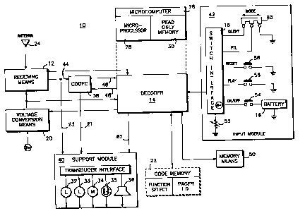
FIG. l shows a functional block diagram
~ applicable to both a first and second embodiment of
the present invention. The paging receiver lO of
the present invention includes a receiving means 12,
a decoding means 14, a memory means SO, a support
9 3~
module 40, an input switch module 42, a voltage
conversion means 20, and a converting means 38. An
antenna 24 receives paging information including
receiver control signals and analog information
including speech signals representative of a voice
message. The antenna 24 is coupled to receiving
means 12 that is subject to the control of decoder
14. The decoder 14 not only controls receiving
means 12, but may also operate receiving means 12 on
an intermittent basis to extend the life of battery
16 through voltage conversion means 20. The
receiving means 12 detects the presence of
electromagnetic energy representing the paging
information and applies the information to the
converting means such as coder-decoder 38. The
coder-decoder 38 converts the received analog
signals, such as real time audio speech signals, to
a stream of binary bits and reconverts stored binary
bits to a replica of the original received analog
signals, such as synthesized audio speech signals.
In the illustrated embodiment, the coder-
decoder 38 (hereinafter referred to as CODEC)
provides for the digital-to-analog and analog-to-
digital conversion of speech signals. The CODEC 38,
such as an adaptive delta modulator, can convert or
encode an audio input signal to a digital data
stream for storage and reconvert or decode a digital
data stream to reconstruct an audio signal. In
particular, the CODEC 38 monitors the real time
audio signal on line 44 and compares it to a past
value that it has recon~tructed and generates a
~ digital bit (sign) that indicates whether the
reconstructed signal's voltage level is higher or
lower t,han the present input value. The CODEC 38
then tries to adapt the reconstructed signal voltage
-10- '~?~ g~
to mirror the present value at the audio input by
varying or modulating a current. The current
charges or discharges a capacitor (not shown) which
changes the reconstructed signal's voltage. The
digital output on line 46 is the sign bit which
indicates whether the reconstructed signal is behind
the input or lower in voltage (logic ~0~) or ahead
of the input or higher in voltage (logic ~1~). The
CODEC's digital output is stored in memory 50 and
retrieved on line 48 to reconstruct a synthesized
audio signal on line 21, thus closely replicating
the real time audio signal in both amplitude and
frequency. One example of such a coder-decoder is
disclosed by N.S. Jayant in the publication
~Adaptive Delta Modulation with a One-Bit Memory~,
Bell System Technical Journal, Vol. 49, No. 2, March
1970. The CODEC 38 is designed to operate at
sampling rates (bit or clock rates) of 16 KHz, 25
KHz, and 33 KHz. The obvious implication of the
three rates is that for slower clock rates, longer
messages can be stored in a fixed amount of memory
at the expense of a lower signal to noise (S/N)
ratio. For example, at a 100 mV P-P 1 KHz signal at
the input, the si~nal to noise degradation is 11 dB
at 33 XHz, 14 dB at 25 KHz, and 23 dB at 16 KHz.
To conserve power, most of the CODEC 38 is
turned off when there are no read/write operations
to the memory. The output buffers and control logic
are always on since it may be necessary to monitor
the channel or provide a BEEP tone when there are no
messages stored. Keeping the buffers and control
logic on also eliminates the need for additional
current source controls to handle the switching of
an additional current source.
--1 1--
The receiving means 12 is further coupled by
line 23 to a support module 40. Operating in
response to decoder 14, the real time audio signal
on line 23 is applied to support module 40 which
supplies analog or digital signals to one of
annunciation transducers 32-36. In particular,
decoder 14 controls support module 40 to apply
either the real time audio signal on line 23 or the
synthesized audio signal on line 21 to speaker 36.
Decoder 14 is associated with memory means 50
which serves to include information for decoding the
received information and for storing information
received from CODEC 38. The CODEC 38 provides the
analog-to-digital conversion of speech signals on
line 46 which are stored in memory 50 as digital
voice messages. A plurality of digital voice
messages can be stored in memory S0 along with the
status of each voice message. For example, a voice
message may have either a read or unread status.
The decoder 14 also functions to alert the paging
user, store, recall, and playback voice messages.
The paging receiving of FIG. 1 has the
capability of storing selective call voice messages
for providing them to support module 40 according to
the state of a plurality of inputs, such as the
state of the control switches of input module 42. A
switch interface 18 provides input capability for
control switches 54-60. Illustratively, control
switch 54 is an on/off switch for controlling power
from battery 16. Control input 55 is a volume
control for speaker 36. Control switch 56 is a play
switch for playing back voice messages previously
digitized and stored in memory 50. Control switch
58 is a reset switch to reset the paging receiver
system and monitor the real time audio signal.
.r~
--12--
Control switch 60 is a mode switch for operating the
decoder in one of three modes. These modes are the
silent, push to listen (PTL), and normal modes, the
operation of which is explained in detail with
reference to FIG. 4.
Considering FIG. 1 in somewhat further detail,
the battery 16 is shown connected to decoder 14
through a switch interface 18. Battery 16 provides
power to decoder 14 through a voltage conversion
means 20, such as a DC to DC converter. Decoder 14
is additionally connected to a code memory 22
further including regions designated function select
and pager ID. The enclosure of code memory 22 with
a broken line indicates a possibility that such a
device can be made removable and therefore separable
from the rest of the system. Another output 62 of
decoder 14 is coupled to support module 40 to
provide the necessary controls for generating alerts
on one of alert transducers 32-36. The alert
transducers may take the form of an illumination
means 32 and 33, such as an LED, a vibration motor
34, a visible display~counter 35, and an audio
speaker 36. Output 62 also controls whether real
time audio signals on line 23 from receiving means
12 or synthesized audio signals on line 21 from
CODEC 38 are applied to audio speaker 36.
A microcomputer 26 is shown interconnected with
decoder 14 by a broken line. This interconnection
indicates that the hardware decoder may be
functionally replaced entirely by a microcomputer
26. Microcomputer 26 is shown to be further
comprised of a microprocessor 28 and a read only
memory (ROM) 30. The ROM 30 includes the necessary
instructions to operate microprocessor 28 to perform
-13-
the functions as described in FIGS. 7-12B.
Microcomputer 26 will have similar interconnections
as does decoder 14. The replacement of decoder 14
by microcomputer 26 provides the exact same signal
decoding functions and the resulting system function
is indistinguishable to a paging user. Thus, the
function of the two alternative embodiments are
indistinguishable within a device.
B. Operation
The operation of the paging receiver
shown in FIG. 1 is such that the receiving means 12
is capable of receiving messages in any of several
message formats through an antenna 24. The decoder
14 responds to the receive signals to analyze the
data and select one of several decoding schemes for
appropriately decoding the incoming information
received by receiving means 12. As with all paging
devices, the resulting decoded signal is tested for
comparison with a designated pager address contained
in code memory 22. On detecting correspondence
between the received-and decoded signal and the
address in code memory 22, the decoder instructs the
CODEC 38 to digitize the real time analog signal and
provide the digitized signal to the decoder 14 for
storage in one of a plurality of message locations
or slots in memory 50. An alert output signal is
produced by the decoder 14 to generate an alert
indicating to the pager user that a message has been
received and stored. In particular, the alert
output signal from the decoder 14 is supplied to
support module 40 to produce a signal on one of a
plurality of transducers 32-36 indicative of the
receipt of the message. Specifically, upon the
receipt of a message, an unread message indicator 32
r
--14--
is activated and an unread message counter 35 is
incremented. Additionally, if all message slots are
full, a memory full indicator 33 is activated.
Because of the requirements for high speed,
real time signal processing and the requirement of
preserving extended useful life of the battery
contained in paging device, voltage conversion means
20 functions in cooperation with decoder 14 to
conserve battery 16. It may also be appreciated
that the decoder 14 may be designated to operate in
only one of a plurality of possible decoding
schemes. This selective function may be supplied by
the code memory 22 or may be factory preset
independently of the code memory 22. It may also be
appreciated that code memory 22 may contain several
addresses, each one corresponding to the
appropriately selected decoding scheme which is
determined by the decoder 14 in response to signals
received by receiver 12.
In addition, code memory 22 includes a function
select region which is used to select various
features of the pager-device. It is advantageous to
build in the circuitry for all functions and then
provide information in-code memory 22 which
identifies the address of the pager and designates
various combinations of the possible function
annunciation features of the system.
The replacement of a hardware decoder by
microcomputer 26 including microprocessor 28 and the
software included within the read only memory 30
region provides the same diagram with block 14
removed and replaced in its entirety by block 26.
The difference is in the internal functions of the
microcomputer in that instead of the hardware
decoder responding to the receiver 12, the
--15-- ~ r !~i~ I Y
microcomputer 26 uses microprocessor 28 as a
software decoder for processing the received signals
in real time according to the same predetermined
routine as the hardware decoder. After the paging
receiver is selectively identified, microprocessor
28 accesses the read only memory 30 for determining
the correct instructions contained in that memory
for processing the received signals, storing the
signals, and replaying the signals. For a better
understanding of the processing, storing and
replaying of the received signals, attention is
directed to FIGS. 8 through 12B for a detailed
description of the operation of the paging receiver.
Continuing with reference to FIG. l, the
voltage conversion means 20 interacts with the
microprocessor 28 and ROM 30 to conserve the battery
for the system. When the microprocessor 28 detects
the reception of a signal corresponding to a pager
identification contained in the code memory,
microcomputer 28 connects with support module 40 to
produce a signal on one of the plurality of
transducers 32-36 to~produce a signal so that the
pager user is made aware that a message has been
received and stored. F~r either the hardware
decoder or microcomputer, the form of the alert
signal pattern provided to the pager user by either
the decoder or microprocessor is indistinguishable.
To briefly summarize, in either the hardware or
software embodiment, real time analog information
received from a base station by receiving means 12
is applied to CODEC 38 and support module 40.
Operating under control of decoder 14, CODEC 38
converts the analog information to digital
information which is stored in memory 50. Depending
upon the configuration of mode switch 60, the real
-16- ~34~4
time audio information is presented to the user via
speaker 36, an unread message indicator 32 is
illuminated, and unread message counter 35 is
incremented. Upon activating the play switch, a
digitized voice message is selected from memory 50
and applied to CODEC 38. The CODEC 38 reconverts
the digital information to analog information and
supplies the analog information to support module
40. The support module applies the analog signal to
the speaker to produce a synthesized voice message
being a replica of the original analog voice
information.
C. Paging Scheme
While it is clear that many types and
formats of signal coding may be utilized for the
present invention, the preferred embodiment uses a
digital signal system designated as the Golay
Sequential Code. The Golay Sequential Code (GSC) is
a selective call paging protocol based largely on
the current Golay binary paging format. A full
description of the Golay code may be found in a
paper entitled ~Selective Signalling for Portable
Applications~ by Leonard E. Nelson, 28 IEEE
Vehicular Technology Conference, Denver, CO, March
22-24, 1978. The Golay Sequential Code is an NRZ
binary signalling format that has been greatly
modified from the earlier format to accommodate
intermixed tone only, tone and data, as well as tone
and voice paging.
The GSC is an asynchronous paging format which
allows pages to be transmitted individually or in
batches. Maximum message throughput for tone only
and tone and data pages is achieved in the batch
transmission mode, while the individual call mode is
useful in tone and voice paging.
-17- ~ J~
FIG. 2 shows a timing diagram for the normal
message signalling routine for a normal voice page
format. The single call address format consists of
a preamble 64, a control word 65, an address code
66, and for voice paging, an activation code (AC)
68. The preamble serves to divide pagers within the
system into groups for improved battery life, as
well as to uniquely identify GSC transmissions from
other coding schemes to facilitate channel sharing
without sacrificing battery life or false call
integrity. The control word 65 delimits the end of
the preamble and supplies timing information for the
batch mode decoding. The address uniquely
identifies each pager and the AC is used to control
the pager audio circuits in voice paging. The batch
mode of operation allows a string of addresses to be
transmitted following the control word.
While this is normal for the operation of
pagers generally, the address is followed by an
activation code and upon the reception and detection
of the activation code, the individually addressed
pager, depending upon its mode, commences a two-
second alert mode to warn the pager user of the
presence of a subsequent voice message. At the
conclusion of the variable length voice message, the
inclusion of a deactivation control word which, for
the preferred embodiment, is the second detected
occurrence of the activation control word and
results in muting the audio channel.
In addition to enabling pagers to operate in a
battery saver mode, the polarity of the preamble
~ identifies the transmission mode as single call or
batch. For instance, when the preamble words are
transmitted with one predetermined bit polarity, the
single call mode is identified. If the preamble
bits are inverted, the batch mode is indicated.
18
The control word, activation code, and address
code all use a two-word format consisting of 28 bits
of comma followed by two (23,12) code words. The
comma is a zero bit reversal pattern transmitted at
600 bps. The two Golay code words (word 1 and word
2) are separated by a half bit space. The polarity
of the half bit space shall be opposite the first
bit of the second words and the starting comma bit
must be the same polarity as the first bit of the
first word. The control word and activation code
are determined (fixed) for the preferred system.
Word 2 of the control word and activation code are
the inverses of the fixed word. That is, the second
word is the inverse of the first word.
The address format is identical to the control
word and activation code formats regarding the
number of bits, the rules for comma and the half bit
space. The address word 2 may be chosen from any
word of the (23,12) code except for all zeros and
all ones combinations. Thus, there are 4094
potential second words made up of 12 information
bits and 11 parity b-its. The first words are chosen
from a 100 word subset of the Golay code. To
generate the binary bit patterns for the (23,12)
Golay code, the decimal representation of the code
word is converted into binary. This binary
representation is rewritten least significant bit to
the left.
The GSC format allows data pages to be
intermixed with tone only or tone and voice pages.
A data page consists of pager address followed by
one or more data blocks. The data block is
identical in length to an address block and may be
freely substituted for addresses in the batch
operating mode. The single call mode can also be
~ ~ $ ~ ~ J f ¦
--19--
used by following the pager address with the data
message. Data information is transmitted at 600 bps
to minimize the cross falsing probability between
the addresses and data. For a more detailed
description and implement of the Golay Sequential
Code for tone, tone and voice, and data pages,
reference is made to U.S. Patent No. 4,427,980
assigned to the present assignee of the present
invention.
II. Hardware Embodiment
FIG. 3 shows a block diagram for the
hardware embodiment of decoder 14 of FIG. 1. The
hardware decoder 14 includes a radio and switch
interface 80, a controller 70, a DC-to-DC current
20, and a timing and oscillator section 76. The
controller 70 interprets input signals from the
radio and switch interface to accomplish the
read/write operations associated with the receiving,
digitizing, storing, and playing back of messages.
The controller 70 includes a program logic array
sequencer, such as a Monolithic Memories 20L10
programmable array logic, a control hardware section
for controlling the operations of the other sections
of the decoder, a counter section for handling
message queues, a counter section for handling the
physical memory pointers, a memory section for
flagging individual messages as read or unread, a
small state machine to determine the mode status of
the controller, and a multiplexing decoder to
interpret hardware jumper inputs for controlling the
length of messages, maximum n~er of messages, and
the type of memory connected. In addition to
controlling the operation of the sections of the
decoder, the controller operates several sections of
-20-
the controller in a battery saving mode in which
power is selectively disabled from appropriate
sections of the decoder when they are not needed.
For example, at power up, the controller selectively
disables power to the DC-to-DC converter and the
memory interface.
The radio and switch interface 80 buffers
inputs from the receiving unit and switches for
generating the appropriate levels to the controller
and CODEC 38. The radio and switch interface 80 may
take the form of a level shifter, such as a Motorola
MC14504B. The memory interface interfaces the
controller to the main memory of the paging receiver
by providing the necessary address, control and data
transmission signals for storing and retrieving data
to the memory. The memory interface may take the
form of a Memory Management Unit as manufactured by
Motorolatm under their designation MC68451.
Table 1 illustrates the number of messages that
can be stored in the paging receiver using
particular configurations of memory when the CODEC
is operating at a specific bit rate. Even though
the table lists specific memories, it is to be
understood that numero~s other memories can be used
in the practice of the present invention.
Continuing with the above described table, referring
to the 1 megabit CMOS DRAM, if the paging receiver
is configured for two messages and the CODEC is
operating at 25 kilobits per second (KbPS), Table 1
illustrates that 20 seconds of voice information can
be stored in one message slot. As is evident from
~ Table 1, the CODEC operates in a plurality of
operating rates such as 16 XbPS per second, 25 KbPS
per second, and 32 KbPS per second. The operating
-21-
rates can be selected by jumper connections within
the paging receiver or by switches external to the
paging receiver.
-22-
Table 1
Message Length as a Function of Bit Rate
and Memory Size
One 256R CMOS DRAM
Number of
Messages 16 KBPS25 KBPS 32 KBPS
1 16 second 10 second 8 second
2 8 second 5 second 4 second
Two 256R CMOS DRAMs
Number of
Messages16 KbPS 25 KbPS 32 KbPS
1 32 second 20 second 16 second
2 16 second 10 second 8 second
4 8 second 5 second 4 second
One 1 Meg CMOS DRAM
Number of
Messages16 KbPS 25 KbPS 32 KbPS
1 64 second 40 second 32 second
2 32 second 20 second 16 second
4 16 second 10 second 8 second
--2 3-- ~ r
Pursuing FIG. 3 ~ the timing and oscillator
section 76 provides the necessary timing signals and
clock signals for all circuits in a manner well
known in the art. The timing and oscillator section
may take the form of a programmable timer/oscillator
manufactured by Motorola under the designation
MC14554lB.
The DC-to-DC converter 20 provides the
necessary operating voltage to the memory from one
or two cell batteries. The DC-to-DC converter 20
also includes current sources to provide power for
the remaining circuitry. In addition to the
detailed diagram of the hardware decoder, the CODEC
38 is shown operatively coupled to the hardware
decoder. The CODEC 38 digitizes real time audio
information and provides the digitized data to the
memory in phase for appropriate storage under the
control of controller 70. When the paging receiver
is operated in the play state, the CODEC under
control of controller 70 receives data via memory
interface 72 and converts the digitized data to
synthesized audio information which is provided to
the paging receiver user as synthesized audio.
III. Operation
Referring to FIG. 1, in the operation of
the paging receiver system, the paging receiver
includes an on/off control switch 54, a reset switch
58, a mode switch 60, a volume control 55, a
playback or play switch 56, a memory unread
indicator 32, a memory full indicator 33, and an
unread message counter 35. The on/off control 54
operates to turn the paging receiver on and off.
The reset switch 58 resets the paging receiver by
returning it to its standby or quiet state. The
-24- ~ B~
reset switch also functions as a real time audio
channel monitor control, whereby activating the
reset switch at any time allows the user to monitor
the real time audio channel. The mode switch 60
places the paging receiver in different modes. The
modes of operation of the paging receiver are the
normal, push to listen (PTL), and silent mode. For
a better understanding of the different modes of
operation, attention is directed to FIGS. 4-7
wherein the modes of operation are described in
detail.
The volume control 55 varies the loudness of
the paging receiver's audio. The play switch 56
operates to retrieve messages from memory. The
memory unread indicator, such as an LCD or LED,
indicates that the paging receiver has received a
message that has not been heard by the user. The
memory full indicator indicates that all memory
slots include a message and that the next message
received will overwrite the oldest message received
in time in memory. The unread message counter 35
indicates the number of unread messages stored in
memory. ~
The explanation now proceeds to FIG. 4 which is
a block diagram showing the operating states of the
paging receiver of the present invention. The
operating states comprise the standby, record, play,
and reset ~tates. Initially, the paging receiver is
turned on and the paging receiver, depending upon
the mode of operation, begins to monitor the
communication channel for information, step lO0. If
~ the paging receiver is in the normal or PTL modes,
the real time audio channel is enabled, step 102.
Enabling the real time audio channel permits the
user to hear the real time audio information. The
-25-
play switch is activated for extinguishing the real
time audio and the paging receiver state is
transferred from the turn on state to a standby or
quiet state 108 via steps 104 and 106.
Additionally, upon activation of the play switch, a
memory empty tone is produced until deactivation of
the play switch, step 105.
Referring back to step 104, if the reset switch
is activated, upon deactivation, the reset switch
extinguishes the real time audio, step 106.
Eventually, after turn-on, the reset or play switch
is activated and the paging receiver system is
vectored to the standby state 108. Upon occurrence
of an incoming message 110, activation of a play
switch 112, or activation of the reset switch 114,
the paging receiver system i5 vectored to either a
record state 116, a play state 118, or a reset state
120, respectively. The explanation now proceeds to
a discussion of each of the states.
A. Record State
In th~ record state 116, depending
upon the position of the mode switch, one of three
modes are selected, either the normal, silent or PTL
mode.
1. Normal Mode
In the normal mode, after
detecting incoming information, the paging receiver
alerts the user with an alert characteristic of the
decoder type, either a tone or vibrate alert. The
alert i5 then followed by the voice message.
Simultaneously, the voice message is being recorded
in memory and may be retrieved any time after
storage. At any time during the record (storage)
cycle, the activation of the play or reset switch
extinguishes the real time audio. Before storage is
complete, the user can again monitor the channel
with either the play or reset switch. If the audio
is not reset at the end of storage, the paging
receiver continues to monitor the channel until a
activation of the play switch or reset switch. In
practice, the paging receiver of the present
invention has a limited storage time allocated to a
given audio message, depending upon the amount of
memory that is used within the paging receiver. If
the voice message continues past the maximum storage
time, the user may listen to the message in real
time in its entirety but will not be able to replay
the entire message since recording terminates after
the predetermined storage time. On the other hand,
if the message is shorter than the predetermined
storage time, the paging receiver stores any channel
noise after the message until the memory slot is
filled.
Referring to FIG. 5, upon the occurrence of an
incoming page and the selection of the mode switch
to the normal mode, the operational state of the
paging receiver is transferred to the normal mode,
step 122. The message counter is incremented by one
to indicate the recording of a new message 124. In
the normal mode, the user is alerted and, depending
upon the memory configuration of the paging
receiver, a predetermined number of seconds (X),
such as eight seconds (see Table 1 for examples of
X), of voice information is recorded in the first
available message memory slot, steps 126 and 128.
The user is able to listen to the real time audio at
the same time it is being recorded. Activating or
deactivating the play or reset switch extinguishes
-27- ~ fl r~ t
the real time audio, step 130. Activating the play
or reset switch (only if the storage cycle is not
complete) again enables the real time audio, step
132. After recording ~X~ seconds of a voice
information, the recording is terminated and the
paging receiver continues to monitor the channel.
If any voice information continues to exist after
the predetermined number of seconds, it will be
output in real time audio to the paging receiver
user until extinguished. After the voice
information is extinguished, real time audio output
is terminated and the paging receiver system returns
to the standby state, step 108.
2. Push to Listen (PTL~ Mode
During receipt of a page in the
PTL mode, the paging receiver alerts the user and
indicates an unread message. However, instead of
outputting voice audio as in the normal mode, the
audio is automatically reset (no audio presented to
the user), although the message does get recorded at
that time. Upon activation and continued activation
of either the play or reset switch, a user can hear
a message in real time. At this time, the message
is considered to be read. On the other hand,
activating either switch during the alert but
releasing it before the voice audio begins does not
constitute reading of a message and the unread
indicator remains active. Before the record cycle
has ended, continued activation of either the play
switch or reset switch monitors the channel. The
subsequent release of the ~witch resets the paging
receiver to its standby or quiet position.
In the PTL mode 134, the unread message
counters are incremented to indicate a message
l~o~oll
-28-
received, step 136. The unread message indicator is
subsequently enabled to indicate to the user an
unread message is recorded in memory, step 138. The
user is alerted and the voice information is
recorded for ~X~ seconds, steps 140-142. To hear
the voice information in real time, the play or
reset switch must be activated, step 144. The
message is now considered ~read~. Upon recording
for ~X~ seconds of voice information, the system
returns to the standby state 108, but the user can
continue to monitor the real time audio via either
switch as long as the activation of the switch
occurred before the termination of the record state.
3. Silent Mode
Upon receiving an incoming
messaqe, recording begins and the unread indicator
is activated. If during the incoming voice message
activation of either the play or reset switch
occurs, the voice message is applied to the speaker
transducer to provide a real time audio message.
Once the record cycle has ended, the paging receiver
alerts the user of a page. If the paging receiver
includes a vibrator, the activation of either the
play or reset switch resets the vibrator. After
resetting the alert, activating the play switch
permits the continued output of the voice message.
This allows a user to stop vibration within the
paging receiver without having the page
automatically omitted. As in the push to listen
mode, a message is considered unread and the unread
indicator is activated. If the reset switch i5
accidentally pressed prior to the detection of a
page (i.e., audio is enabled while a page is
detected), the paging receiver reverts to the normal
-29~ 3 ~? ~3 1
mode and must be manually reset. If the reset
switch is activated after detection of the page, the
paging receiver monitors the channel with no
reversion to the normal mode.
Continuing with reference to FIG. 5, in the
record state 116, if the mode switch is set to the
silent mode position, an incoming page transfers the
paging receiver from the standby state 108 to the
silent mode 146. First, the unread and message
counters are incremented and the unread message
indicator activated, steps 148 and 150. In the
silent mode, no audible al-rt is generated, however,
a paging receiver that is equipped with a vibrator
will vibrate after storage for a predetermined
number of seconds, steps 152-154. After ~X~ seconds
of data are recorded, the system returns to the
standby state 108.
In any of the above modes, except when
alerting, activation and continued activation of the
reset switch provides real time channel monitor.
Also, in any of the above modes, if memory is full,
an incoming message c~uses the oldest message to be
overwritten, regardléss of whether it is read or
unread.
B. Play State
Referring to FIG. 6, from the standby
state 108, the activation of the play switch
transfers the system to the play state 118 to begin
replaying of the stored messages from most recent to
oldest. If the play switch is activated with no
messages in memory, a two KHz Jmemory empty~ tone
sounds for the duration of activation indicating
that the paging receiver is functioning but no
messages have been received since turn on, steps
~ ~r ~ ~ E3 ~ !1
~30~
160-164. The system then returns to the standby
state 108 when the switch is deactivated, step 165.
Referring back to step 160, if messages exist, then
the most recent messaqe is played from memory by
~ynthesizing the audio, step 166. Reference is made
to FIGS. lOA-ll for a more detailed discussion of
the operation of playing back stored voice messages
via a microprocessor. If the reset switch is
activated and deactivated at any time during the
replay operation, replay is aborted by extinguishing
the synthesized audio and the paging receiver
returns to the standby state 108 after the reset
switch is deactivated, steps 168-170. While the
reset switch is activated, the real time audio is
enabled.
Referring back to step 168, if the play switch
is not activated during the replay of a message, the
paging receiver returns to the standby state at the
end of the message, unless there is an unread
message in memory, steps 172-174. If an unread
message in memory exists, it is also replayed with a
one-half second two KHz tone separating the
messages. It is impôrtant to note that messages are
automatically played in reverse chronological order,
so if a read message exists between two unread
messages, the read message is also heard.
The activation of the play button during replay
of any message causes the pager to jump ahead and
begin replay of the next most recent message in
storage, steps 174-176. Activation of the play
button during the replay of the oldest message in
~ memory returns the pager to its initial standby
state, step 178.
To clarify the issue of a ~read~ message, a
message is considered ~read~ when the first two
second~ of the message slot are played even if no
o o o ~
-31-
voice is present. This prevents accidental clearing
of the unread message flags if the user wants to
reset his pager to the standby mode by cycling
through the messages with the play switch.
If a new page is received during the replay
operation, the replay is aborted and the paging
receiver reverts to the normal mode. At the end of
the incoming message, manual reset quiets the paging
receiver. Once reset, the pager returns to the
previously chosen mode of operation.
As previously stated, only messages received
while in the silent or PTL modes are considered
unread and are tracked by the unread message
indicator. Messages heard in the PTL mode by
holding down the play or reset switch following the
alert are considered ~read.~ Once all messages are
read, the unread indicator is extinguished.
In the PTL or silent mode, a change made to the
normal mode indicates that the user is now available
to hear messages. Therefore, if there exists any
unread messages in storage, all stored messages
(whether read or unre-ad1 automatically begin playing
in reverse chronological order until all unread
messages are played out. Each message is separated
by a one-half second two KHz tone. Pushing the
reset switch extinguishes the synthesized audio tone
portion of the message. At that time, the first
message that is played is considered read if the
first two seconds of the memory slot have expired.
Any other unread messages remain unread and the
unread message indicator continues to be active. If
the most recent message is unread, pushing the reset
switch cancels the unread message indicator (after
the first two seconds) and resets the paging
receiver to its standby state. Any other mode
changes do not affect the messages.
-32-
C. Reset State
Referring to FIG. 7, the activation
and deactivation of the reset switch transfers the
system to the reset state 120. If the mode switch
is set to the normal mode, the real time audio is
enabled, steps 180-186. If the silent mode is
selected, the real time audio is enabled, steps 182-
188. Finally, if the PTL mode is selected, the real
time audio is also enabled, steps 184-190. The
system is then returned to the standby state 108.
Prior to relating the above operation to the
microprocessor embodiment of the paging receiver
system, a summary of the operations in general may
merit review. The following tables include a brief
description comparing the operation of the play
button and reset button during different operating
states of the paging receiver system.
-33- 1~4~00~1
Table 1
NORMAL MODE
PLAY BUTTON RESET BUTTON
After Activating the Extinguishes
turn-on switch extinguishes real time audio
alert the real time audio channel upon
and outputs the 2 deactivation.
KHz ~memory empty~
tone for duration of
activation. Upon
deactivation, the
2 KHz tone i8
extinguished.
Stand~y With each succesive Monitor real
activation, initiates time audio.
playback of the next
message in queue.
T f playing oldest
message,~activation
switch returns radio to
standby state. If no
messages are stored, a
~memory empty~ tone is
generated upon switch
activation.
During
Alert No action. No action.
During
Voice Extinguishes real time Extinguishes
audio upon switch real time audio
deactivation. upon switch
deactivation.
-34- ~ )OLI
Table 2
PTL (PUSH-TO-LISTEN) MODE
PLAY BUTTON RESET BUTTON
After Activating the switch Extinguishes
turn-on outputs a 2 XHz real time audio
~memory empty~ tone upon
for duration of deactivation.
activation. R-sets
real time audio
channel on activation;
resets 2 XHz tone upon
deactivation.
Standby With each successive Monitor real
activation, initiates time audio
playback of the next channel.
message in queue. If
playing oldest message,
activating switch
returns radio to standby
state. tf no messages
are stored, a ~memory
empty~ tone is
generated upon switch
activation.
During
Alert No action. No action.
During
Voice Listen to audio real Listen to audio
time. ProvideS real time.
limited channel
monitoring capability.
-35~ Q f~'l
Table 3
SILENT MODE
PLAY BUTTON RESET BUTTON
At Radio vibrates for a Radio vibrates
turn-on predetermined time a predetermined
alert period such as 8 period such as 8
seconds or until seconds until
play switch is reset switch is
activated. activated.
Standby With each successive Monitor real
activation, initiates time audio
playback of the next channel.
message in queue.
If playing oldest
message, activating the
switch returns radio to
standby state. If no
messages are stored, a
'memory empty' tone is
generated upon switch
activation.
During
Alert Resets vibrate alert. Resets vibrate
alert.
During
Voice (By chance) Listens to (By chance)
real time incoming Listens
audio. However, to real time
message is not incoming audio.
considered read. However, message
is not
considered read.
B~
-36-
IV. Microprocessor Embodiment of the Present
Invention
FIGS. 8-12B are flow charts explaining the
programs or routines as stored in the read only
memory 30 to operate the microprocessor
implementation of the paging receiver.
A. Power On Routine
Referring to FIG. 8, there is shown a
flow chart for the power on sequence which takes the
paging receiver from the off mode to the standby
mode. Upon power up, the system is vectored to the
power on reset routine, step 192. The power on
reset routine initializes the hardware and the
software to process the incoming paging information
and to store the digitized voice information in the
appropriate memory slots as received. Specifically,
STATE, ALPHA, and BETA variables are reset to
initial conditions. Briefly, STATE relates to
playing back the message in chronological order from
earliest to oldest. ALPHA points to the memory slot
having the most recent message. BETA points to the
memory slot having the next most recent message.
Their use will become apparent with reference to the
remaining fiqures. After basic housekeeping is
completed, the power on routine passes control to
the open routine, step 194. The open routine
enables the real time audio channel to allow the
paging receiver to listen to incoming information.
Upon completion of these tasks, the open routine
passes control to the standby routine, step 196.
~ The standby routine 196 enables the interrupt
system for the microprocessor and prepare6 the
paging receiver to receive incoming information.
The system as illustrated is an interrupt driven
-37- ~ 0~0
system in which an event generates a specific level
on an input line to the microprocessor. In
response, the microprocessor saves the current
executing address and branches to a memory address
which includes a routine to process the interrupt
generated by the event, step 198.
Two methods of implementing the above sequence
are commonly used in microcomputers. These are
called polled interrupts and vectored interrupts.
Polled interrupts are those in which each peripheral
device is tested, using either hardware or software,
until the requesting device is found. Program
execution is then directed to the appropriate
interrupt-service routine which executes the data
exchange. In this method, the priority of the
device is determined by the relative position of a
device in the polling ~equence. In contrast,
vectored interrupts are those in which the event
causes program execution to proceed directly to the
appropriate service routine.
In the illustrated embodiment, the polling
interrupt system is dascribed, however, it is to be
understood that a vectored interrupt system would
work just as well. After the interrupt system is
enabled, the microprocessor waits in the standby
state for an interrupt, step 196.
B. Interrupt Routine
Eventually, an interrupt is caused by
either incoming paging information, the activation
of the reset switch, or the activation of the play
switch, step 198. Upon the occurrence of the
interrupt, the microprocessor is vectored to an
interrupt routine, step 199, a detailed flow chart
of which is shown in FIGS. 9A-B. Since the receipt
-38-
of i~coming paging information, the activation of
the reset switch or activation of the play switch
generates an interrupt, the microprocessor must
determine which condition generated the interrupt.
The microprocessor is vectored to the beginning of
the interrupt routine, step 200. The method then
determines if the interrupt was generated by either
incoming information, the reset switch or the play
switch.
Referring to FIG. 9A, if the interrupt is
caused by an incoming message, the message must be
recorded, step 202. The method vectors the
microprocessor to a record routine which records the
message into one of a plurality of empty message
slots, step 204. If no empty message slots exist,
the message is recorded into the message slot having
the oldest message. A complete disclosure of the
record routine is shown with respect to FIGS. 12A-B.
For purposes of illustration, the paging
receiver of the present invention is shown with only
two message slots. However, a plurality of message
slots can be used which is the subject of copending
application entitled "Prioritization of Stored
Messages in a Digital Voice Paging Receiver", having
Canadian serial number 564,696, filed even date herewith,
invented by Fisch et al., being assigned to the assignee
of the present invention.
Referring back to step 202, it is determined
whether the paging receiver is recording by polling
an encoder line on the CODEC, step 206. If the
system is not in the record state, the system is in
either the play or standby state and the interrupt
was generated either by the play or reset switch,
step 208. If the real time audio is ena~led, this
.. .. . . . . . . . .. .. . ... .... ... . .. . .. . .
--39--
implies the user is monitoring the real time audio
channel in the standby state and the method
extinguishes the real time audio, step 210. After
the real time audio is extinguished, the method
enables the interrupts so as to detect any further
interrupts, step 212. The method then returns.
Referring back to step 208, if the paging receiver
is not recording and the real time audio channel is
extinguished, this implies the system is in the play
state. Thus, the method determines whether the user
has activated the play switch to play back a message
as will be discussed with reference to FI~;. 9B.
Referring back to step 206, if the system is
recording, then the interrupt was generated by
either the play or reset switch during the record
state. The method then senses the mode switch to
determine whether the silent, PrL, or normal modes
are selected, step 216. The method then determines
whether the silent mode is selected, step 218. If
the silent mode is selected, this implies that the
user has activated the play or reset switch to
enable the real time-audio channel. The method
enables the real time audio channel, enables the
interrupts and returns, steps 220, 212 and 214.
Referring back to step 218, the method then
determines if the PTL mode is selected, step 222.
If the PTL mode is selected, this implies that the
user wishes to hear the real time audio while it is
being recorded. Therefore, the method enables the
real time audio channel, step 224. The method then
enables the interrupts, and returns, steps 212-214.
If the system is not in the cilent or PTL mode,
then the system must be in the normal mode, step
226. In this case, it is determined whether the
real time audio is enabled by checking an audio fl~g
_40~ )0
which is set by the record routine, the discussion
of which is given with respect to FIGS. 12A-8, step
228. If the real time audio flag is on, the method
extinguishes the real time audio channel and resets
the audio flag, step 230. If the real time audio
flag is off, the real time audio channel is enabled
and the audio flag is set, step 232. After either
extinguishing or enabling the real time audio
channel, the interrupts are enabled and the system
returns, steps 212-214.
Referring back to step 208, if the real time
audio channel is off and the system is not
recording, then the interrupt is a play switch
interrupt. The method then places the system in the
play state. Referring to FIG. 9B, there is shown a
method for operating the system in the play state.
In the play state, a message is played back
starting with the most recent message. If the next
message is reguired, the play switch must be
activated during the playing of the present message.
Referring to FIG. 9B, if the synthesized audio is
on, this implies that-the next message is to be
played. If the synthesized audio is off, the most
recent message is played back. This is accomplished
by the play ~A~ routine. Briefly, play ~A~ routine
plays the most recent message stored in the two
message slots as determined by the ALPHA variable.
The play ~A~ routine is discussed in detail with
respect to FIG. lOA. If the synthesized audio is
on, the user desires to play back voice information
stored in the next message slot. A variable STATE
indicates if the synthesized audio i8 on or off. If
STATE is zero, then the synthesized audio is off.
If STATE is on, then the synthesized audio is on.
The method first determines if STATE ~s equal to
oL~
-41-
zero, step 238. If STATE is zero, the system
executes the play ~A~ routine which will play the
most recent message after the present synthesized
audio message terminates.
Referring back to step 238, since the routine
play ~A~ sets the variable STATE equal to one during
its execution, the most recent messaqe is playing.
If the play switch is activated during the most
recent message, the system plays back the second
most recent message, step 242. Since the system
finds the variable STATE equal to one, the system is
vectored to a play ~B~ routine, step 243. The play
~B~ routine plays the second most recent message.
At the beginning of the play ~B~ routine, the STATE
variable is set egual to two. Referring back to
step 242, if the play switch is activated during the
play back of the second most recent message, the
method vectors the system to extinguish the
synthesized audio channel, steps 244-246. The
method then sets the variable STATE equal to zero so
that repeated activation of the play switch causes
the system to repeat-steps 234-248. If the state is
higher than the number o~ message slots (as
illustrated two message slots), then a
microprocessor failure has probably occurred and the
system ~umps to the power on reset for
reinitialization of the microprocessor, steps 247
and 249.
C. Play A Routine
FIG. lOA ~hows a flow chart for the
play ~A~ routine which plays the most recent message
from one of two message slots in the paging
receiver. The method begins by setting the variable
STATE egual to one to notify the system that the
-42-
most recent message is being played, step 2S0. In
addition to setting the variable STATE equal to one,
the synthesized audio channel is activated, step
251. The method then enables the interrupt to allow
the system to respond to incoming information, step
252. If paging information is received during the
play routine, the play routine is terminated and the
paging receiver responds to the incoming paging
information. The method then determines if there
are any unread messages, step 254. If there are
unread messages, the system is vectored to an unread
message routine.
Referring back to step 254, if there are no
unread messages, then the method checks to determine
if there are messages stored, step 256. A variable
ALPHA, dependent on the number of messages, is
analyzed. If ALPHA equals zero, then no messages
are in the receiver and the system generates a
~memory empty~ tone to indicate that there are no
stored messages, steps 256-258. The system then
deactivates the synthesized audio channel and waits
for incoming paging ~nformation or for a user input,
steps 260 and 262.
Referring back to step 256, if there are stored
messages, then it is determined if the most recent
message is in slot one or slot two. If ALPHA equals
one, the most recent message is in the first message
slot, step 264. The system begins reading the
digitized data in the first message slot and
providing a replica of the original audio
information on the synthesized audio channel to the
user, step 266. After playing back the most recent
message, the system extinguishes the synthesized
audio channel and returns, steps 260-262.
_43~
Referring back to step 264, if ALPHA is not
equal to one, then ALPHA is equal to two or greater.
If ALPHA equals two, the most recent message is in
slot two and the system reads the digitized data
from slot two and provides synthesized audio to the
user, step 270. After playing back the synthesized
audio from message slot two, the system extinguishes
the audio channel and returns, steps 260-262.
Referring back to step 268, if ALPHA is greater
than two, a malfunction has occurred in the
microprocessor. Thus, the system is vectored to a
force reset, step 271.
Referring back to step 254, if there are unread
messages, the system is vectored to an unread
message routine as shown in FIG. lOB. Referring to
FIG. lOB, the unread message counter is decremented
to signify the playing back of an unread message,
step 272. Next, the interrupts are enabled so the
system can respond to incoming information, step
274. Next, ALPHA is tested to determine the
location of the most recent message. If ALPHA
equals one, the most recent message is in the first
message slot and the system reads the digitized
voice information from the most recent and plays a
replica of the information on the synthesized audio
channel, steps 276 and 278. After playing back the
message from the first message slot, it is
determined if there are any other unread messages
remaining, step 280. If the answer is yes, then the
system is vectored to the play ~B~ routine which
plays back the second most recent message. Since in
the illustrated embodiment there are only two
message slots, the playing back of the second most
recent message indicates no unread messages remain.
Therefore, the unread message indicator is
-44-
extinguished, step 291. The play ~B~ routine is
then executed, step 292.
Referring back to step 276, if ALPHA is not
equal to one,-then it is determined if ALPHA eguals
two, step 282. If ALPHA equals two, then the most
recent message is in the second message slot and the
system plays back the digital stored voice in the
second message slot, step 284. After playing back
the digital information in the second message slot,
it is determined if there are any unread messages,
step 280. If so, then the second most recent
message is played, steps 291 and 292. Referring
back to step 282, if ALPHA is not egual to one or
two, then there are no messages to play and the
synthesized audio channel is extinguished, step 286.
The system then returns to the standby state, step
290.
D. Play B Routine
The play B routine plays back the
second most recent message from either one of the
message slots. The play ~B~ routine is executed
after the play ~A~ routine executes. Referring to
FIG. 11, the routine is entered and the variable
STATE is set equal to two for notifying the system
that the second most recent message is to be played,
step 300. The synthesized audio channel is then
activated and the interrupts enabled to allow the
paging receiver to respond immediately to incoming
paging information, steps 302 and 304. It is then
determined if any unread messages are available,
step 306. If there are unread messages available,
then the unread message counter is cleared, since
all unread messages will have been read after the
play ~B~ routine replays the oldest message in a
two-message slot system, step 308.
_45~
The method then determines the value of a
variable named BETA. BETA determines whether the
second most recent message is either in the first
message slot or the second message slot. If BETA
equals zero, there is no second most recent message
and the system is vectored to the standby state
after deactivating the audio channel, steps 310-314.
If BETA is not egual to zero, then BETA is tested
for the value one, step 316. If BETA eguals one,
the second most recent message i8 in the first
message slot and the system plays back the second
most recent message contained in the first message
slot by synthesizing the digital voice information
through the CODEC and replicating the voice
information on the synthesized audio channel, step
318. After the synthesized voice information is
played back, the system deactivates the synthesized
audio channel and returns, steps 312-314.
Referring back to step 316, BETA is checked for
the value two, step 320. If BETA eguals two, then
the second most recent message is in the second
message slot and the-system plays back the digitized
voice information in the second message slot through
the CODEC to the synthesized audio channel, step
322. After the voice information is played back,
the system returns to the standby state, step 314.
E. Record Routine
FIGS. 12A-B show a detailed flow chart
for the record routine of the present invention.
The record routine records the digitized audio
signal from the CODEC in the appropriate message
slot and tags the message as the most recent
message.
-46-
The routine begins by updating the message
pointers, ALPHA and BETA, step 350. In a two-slot
message system, since ALPHA points to the most
recent message, the message being recorded will
replace the second most recent message pointed to by
BETA. Therefore, the pointers ALPHA and BETA are
swapped so that they point to the most recent
message and second most recent message respectively.
After the values for ALPHA and BETA are swapped, the
method determines the mode of the system, step 352.
The method then determines if it is in the silent
mode, step 354. If the system is in the silent
mode, the unread message indicator is activated to
notify the user that a message has been recorded,
step 356. Next, a silent flag is set to indicate a
message has been recorded in the silent mode, step
358. The real time audio channel is extinguished
and the unread message counter is incremented, step
360. The method then determines which message slot
to store the digitized voice.
Referring back to step 354, if the system is
not in the silent mode, then the system is either in
the PTL or the normal mQde. The method then
determines if it is in the PTL mode, step 362. If
it is in the PTL mode, then the unread message
indicator is activated, a user alert generated, and
the audio real time channel is extinguished, steps
364, 366 and 360.
Referring back to step 362, if the system is
not in the PTL mode, then the system is in the
normal mode, an audio flag is set and a user alert
generated, step 368. The method then determines
which message slot is available for recording by
analyzing the value in the variable ALPHA. If ALPHA
eguals one, then the message is recorded in the
-47-
first message slot, steps 370 and 372. As is
evident, if a previous message is contained in the
first message slot, the previous message is
overwritten. If ALPHA is two, the message is
recorded in the second message slot, steps 374 and
376. If ALPHA is not one or two, then an error has
occurred and the microprocessor is reinitialized,
step 378.
Referring to FIG. 12B, there is shown a
continuation of the flow chart of FIG. 12A. After
recording of the message in the appropriate message
slot, the audio flag is checked, step 380. ~f the
audio flag is set, the real time audio channel is
enabled, step 382. Next, the silent flag is
checked, step 384. If the silent flag has been
previously set by the selection of the silent mode,
a silent alert such as a vibration alert is
generated, step 386. Please note that the silent
alert occurs after recording the message.
Therefore, in the silent mode, messages are
received, digitized, and recorded and then the user
is alerted. After a}erting the user, the silent
flag is reset, step 388. The method then returns to
the standby state, step 390.
Thus, there has been shown an apparatus and
method for transmitting information to a paging
receiver in a plural population of paging receivers.
The tran~mitted information includes control signals
followed by analog information having at least one
analog voice message. The paging receiver of the
present invention receives and decodes the
information to recover the control signals and the
analog information. The control signals provide
receiver control information. The receiver is
selectively enabled correlating to the received
13~@~
-48-
control information. The received analog
information is converted to digital information
being a replica of the analog voice information and
stored in a plurality of message slots in the paging
receiver. In response to a user input, a message
slot is selected and the stored digital information
is recalled and presented to the user. The
synthesized voice information presented to the user
is a replica of the original analog voice message.
It should be apparent from the above
description that numerous variations can be made
from the preferred embo~i~ent described herein
without departing from the scope of the invention.
Reference is therefore made to the claims which~5 follow for a definition of the invention.
What is claimed is: