Note: Descriptions are shown in the official language in which they were submitted.
2 ~ .D~
G-2403
VEHI~LE DIPLEX DOPPLER NEAR-OBSTALE DETECTION SYSTEM
This invention relates to a diplex Doppler
obstacle detection system for a vehicle.
Background of the Invention
Obstacle detection systems for providing an
indication of the distance and/or warning of
approaching objects are known. One application for
such systems is for detecting objects in proximity to
an automotive vehicle. For example, the vehicle may
employ a near-obstacle detection system to alert the
vehicle operator of the presence of obstacles behind
the vehicle while backing the vehicle or to alert the
vehicle operator of any obstacle in front of the
vehicle below the operator's line of sight.
Various systems have been proposed for
near-obstacle detection. One such system is commonly
referred to as a diplex ~oppler system having the
capability of providing range and relative velocity
between the vehicle and an object. In general, a
diplex Doppler radar system transmits two separate RF
signals differing only slightly in frequency and
receives two echo signals which are reflected by an
object in the vehicle path. Each reflected signal is
mixed with the correspondins transmitted signal to
produce a Doppler signal resulting from the relative
motion between the vehicle and the object. Because of
the small change in the wavelength of the transmitted
signals, the two Doppler signals will be shifted in
phase from one another by an amount that is a direct
measure of the distance to the target.
~,~
. ., ' ~ . : .
:. - ~ ',,
2~
For example, with a first RF frequency of
10.525 Ghz, a Doppler signal resulting from mixing the
generated signal with a signal returned from an ob~ect
will result in a 31.37 Hz/mi/hr Doppler frequency
shift. A second RF signal having a frequency of 10.531
Ghz when mixed with a signal returned from an ob~ect
will result in a Doppler frequency shift of 31.38
hz/mi/hr. Because of the small change in wavelength,
the phase of the first Doppler return signal will be
slightly shifted in phase from the second Doppler
return signal for a given target distance. The further
the distance to the target, the greater the phase
shift. In this example, a phase shift from zero to 70
corresponds to a range of 0 to 16 ft.
In order to extract the range information, the
typical system provides for converting the two Doppler
signals into two rectangular signals, which in turn are
provided to the input terminals of an exclusive OR
gate. The output of the gate is a signal having a duty
cycle (the percentage of the pulse width to the overall
signal cycle) that is a direct measure of the distance
between the vehicle and the obstacle. The duty cycle
modulated signal is then provided to a filter circuit
whose output is an analog voltage having a magnitude
representative of the range between the vehicle and the
obstacle.
Characteristic of the foregoing system is that
a large time constant filter is required in order to
convert the duty cycle range information to a DC
voltage range signal with acceptably low ripple. This
results in a significant lag and therefore error in the
signal indication of the range to a fast moving object.
'
2~ if.3
Summary of the Invention
In accord with this invention, a vehicle
near-obstacle detector is provided in the form of a
diplex Doppler radar system such as described above but
which provides for accurate range information even for
high relative velocities between the vehicle and an
ob~ec~.
In accord with the principles of this
invention, it is recognized that the error introduced
by the filter circuit converting the duty cycle signal
to a DC voltage is in direct proportion to the relative
speed between the vehicle and the ob~ect.
Particularly, at low speeds the lag introduced by the
filter circuit is small relative to the duty cycle
signal cycle time thereby having little effect on the
analog signal range indication. However, with
increasing closing rates between the vehicle and the
obstacle, the lag introduced by the filter circuit
increasingly effects the analog signal range indication
as the filter time constant increasingly becomes more
significant relative to the duty cycle signal cycle
time.
Since the ran~e is calculated by the phase
shift between the two Doppler signals, the sub~ect
invention provides for a closing rate dependent
compensation to the lag of the duty cycle to DC
conversion filter by introducing a small time shift in
the signal path of one of the Doppler signals to effect
a shift in the range indication provided at the output
of the duty cycle to DC conversion filter. The phase
shift of the Doppler si~nal path represented by this
time shift is small at low Doppler signal frequencies
. ~ ~
.
2~
corresponding to low closing velocities between the
vehicle and the obstacle with the phase shift
represented by the time shift increasing with
increasing frequencies of the Doppl~r signal
corresponding to increasing closing speeds between the
vehicle and the obstacle. This increasing phase shift
introduced by the time shift with increasing
frequencies of the Doppler siqnal is a compensation for
the increasing arror introduced by the lag of the duty
cycle to DC conversion filter with increasing
frequencies of the Doppler signals. In this manner,
the error of the duty cycle to DC conversion filter may
be sub~tantially eliminated over the Doppler frequency
range of the radar system.
Description of the Drawings
The invention may be best understood by
reference to the following description of a preferred
embodiment of the invention and the drawings in which:
FIGURE 1 depicts the application of the
near-obstacle detection system of this invention to
sensing an ob~ect behind an automotive vehicle;
FIGURE 2 is a diagram illustrating the
transmitted and received RF signals from a diplex
Doppler radar system carried by the vehicle of FIGURE
l;
FIGURE 3 is a general diagram of the diplex
Doppler near-obstacle detection system incorporating
the principles of this invention; and
FIGURE 4 illustrates diagrams of various
waveforms of the system of FIGURE 3.
~ .
- .
- 2~
Description of_a Preferred Embodiment
The near-obstacle detection system of this
invention is illustrated in FIGURE 1 as applied to an
automotive vehicle 10 for sensing an obstacle 12
located a~ a distance D from the rear of the vehicle.
As can be appreciated, it is desirable to provide to
the vehicle operator an indication of the presence of
the obstacle 12 and its distance D from the vehicle 10
when the vehicle 10 is in reverse and being backed
toward the obstacle. The radar system in this
embodiment provides a signal (audio, visual or both)
having a frequency that is indicative of the distance D
of the obstacle behind the vehicle. It is, of course,
understood that the radar system may be used to detect
ob~ects in proximity to the vehicle other than
rearward, such as for objects that are in front of the
vehicle that may be below the operator's line of sight.
The radar system utilized in the vehicle 10 of
FIGURE 1 is, as previously described, a diplex Doppler
continuous wave radar system. In this form of system,
two continuous wave signals of slightly different
frequency are transmitted, reflected from an object
such as the obstacle 10 and mixed with the
corresponding transmitted signals. A pair of Doppler
signals result from relative motion between the vehicle
and the obstacle 12. The phase difference between the
Doppler signals is a direct measure of the distance
between the vehicle 10 and the obstacle 12. `
Referring to FIGURE 2, the diplex Doppler
radar system is generally illustrated as including a
voltage controlIed oscillator (VCO) 14 for generating
RF signals. The VCo 14 is modulated by the output of a
,, .. .. ~ . . . . . .
;. .
- ~.
.
2~
squarewave signal generator 16 providing alternating
voltage levels to the VC0 14 ~o as to alternately
generate two RF signals slightly shifted in frequency.
In this embodiment, it will be a6sumed the voltage
output of the squarewave sign2l1 generator 16 shifts
between two voltages which cause the RF signal output
of the VC0 14 to switch between RF frequencies of
10.525 Ghz and 10.531 Ghz. The squarewave signal
generator 16 may take the form of a Schmidt-trigger
10 oscillator squarewave generator having a 30 microsecond
period and a variation of 25 millivolts peak-to-peak.
The RF signal output of the voltage controlled
oscillator 14 is provided to a transmitting antenna 18
which transmits the continuous wave RF signal
alternating between the two frequencies rearward from
the vehicle 10. If an object, such as the obstacle 12,
is present behind the vehicle, the transmitted signal
is reflected and received by a receiving antenna 20.
The receivad RF signal is coupled from the antenna 20
20 to an RF input of a conventional mixer 22. A local
oscillator signal L0 is provided to the mixer 22 from
the output of the voltage controlled oscillator 14 by
means of a coupler 24.
The output of the mixer 22 is an IF signal
comprising the Doppler signals associated with each of
the frequencies of the RF signal provided by the
VC0 14. This IF signal is provided to a processing
circuit 26 which functions in accord with this
invention to provide audible and/or visual indications
30 of the range D between the vehicle 10 and the obstacle
12.
. . :
- :
.. .
2~
The Doppler frequency at the output of the
mixer 22 when the RF signal output of the VCO 14 is at
the higher freguency is slightly greater than the
frequency of the Doppler signal output of the mixer 22
when the frequency of the RF signal output of the VCO
14 is at the lower frequency. As will be described, by
detecting the phase shift between these two Doppler
signals range to the obstacle 12 may be determined.
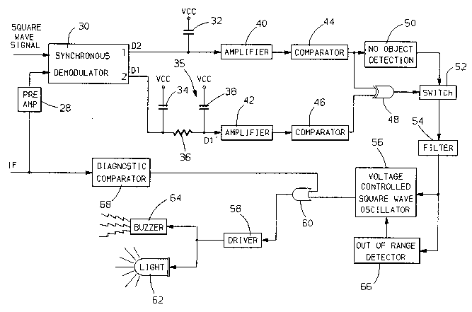
Referring to FIGURE 3, details of the
10 processing circuit 26 are illustrated. The IF signal
from the mixer 22 is provided to a wide band
preamplifier 28 whose output is coupled to a
synchronous demodulator 30 driven by the squarewave VCO
`modulation signal output of the generator 16. This
signal is provided to the switch input of the
synchronous demodulator 30. By using the same
squarewave si~nal from the generator 16 used to control
the VCO 14, the synchronous demodulator 30 provides for
separation of the Doppler signals associated with the
20 two frequencies of the RF signal output of the VCO
14. Particularly, the synchronous demodulator provides
on one output a Doppler signal Dl having a frequency F1
associated with the higher RF signal frequency 10.531
Ghz and provides on a second output a Doppler signal D2
having a frequency F2 associated with the lower RF
signal frequency 10.525 Ghz.
In order to provide for substantially
continuous wave Doppler signals, the Doppler signal D2
output of the second channel of the synchronous
30 demodulator is held during the period the first channel
is selected by means of a capacitor 32 coupled to a
regulated voltage source VCC. The capacitor 32 is
.... , ., . . . ~ ~ .
~ ,, , , , ~
: . . :
: -
z~
charged by the Doppler signal D2. Similarly, when thesecond channel is qelected by the squarewave signal,
the Doppler signal D1 is held by a capacitor 34 coupled
to the voltage source VCC and charged by the Doppler
signal Dl. ~he resulting subfitantially continuous
Doppler signals are illustrated in FIGURE 4a. The
Doppler signal D2 is shifted in phase relative to the
Doppler signal Dl by an amount that is directly
proportional to the distance D between the vehicle lO
and the obstacle 12.
The Doppler signal Dl output of the second
channel of the synchronous demodulator 30 is then time
shifted by a time delay circuit 35 comprised of a
resistor 36 and a capacitor 38 coupled between the
regulated voltage VCC and the synchronous demodulator
30. The shifted Doppler signal Dl~ is provided at the
junction of the capacitor 38 and the resistor 36 and is
illustrated in FIGURE 4a. The time shift provided by
the time delay circuit 35 is substantially constant
over the Doppler frequency range of the near-obstacle
detection system.
The Doppler signal D2 is amplified by an
amplifier 40 and the time shifted Doppler signal D1~ is
amplified by an amplifier 42. The amplifiers 40 and 42
are identical and provide for amplification of the
Doppler signals and further may provide for signal
limiting.
A pair of comparators 44 and 46 convert the
analog signal output of the amplifiers 40 and 42 into a
sguarewave logic signal having a 50~ duty cycle at the
frequency of the individual Doppler signals Dl' and D2.
These squarewave signals are illustrated by the solid
` - ~ ~ . ,
:. ...
-- 2~
line sguarewave signal 45 of FIGUR~ 4B extending from
time t2 to time ts and which is associated with the
Doppler signal Dl~ and the squarewave.signal 47 of
FIGURE 4C extending from time t3 to time t6 and which
is associated with the time shifted Doppler signal D2.
The squarewave signal outputs of the comparators 44 and
46 are coupled to inputs of an exclusive NOR circuit 48
which provides logic output siqnal~ a~ illustrated by
the solid line logic signals of FIGURE 4D. In general,
the output of the exclusive OR gate 48 provides signal
pulses that are high during the non-overlapping periods
of the Doppler signals D1' and D2. ~he duration of
each pulse of the pulse train output of the gate 48
represents the phase shift between the Doppler signals
Dl' and D2. The duration of each pulse (such as from
t2 to t3 and from ts to t6) in relation to one half the
period of the Doppler signals establishes a dut~ cycle
signal whose duty cycle value represents the phase
shift between the Doppler signals D1' and D2.
In the present embodiment, a no object
detection circuit 50 provides an output for controlling
a switch 52 which is controlled to be conducting or
non-conducting depending on whether an obstacle is
sensed rearward of the vehicle 10. In general, the no
ob~ect detection circuit 50 determines the absence of a
toggling of the output of the comparator switch 44 to
control the switch 52. Assuming an object is present
in combination with relative motion to the obstacle
resulting in the Doppler signal D2 and a switching in
3Q the output of the comparator 44, the no ob~ect
detection circuit 40 controls the switch 52 to a
.... .. ~
, .
.: :
.. . : .
: . . . -
2~2~ s
conducting ~tate to couple the output of the exclusive
OR gate 48 to a filter 54.
As preYiously described, the outpu~ of the
exclu~ive OR gate 48 coupled to the filter 54 is a duty
cycle signal that is a direct measure of the phase
shift between the Doppler signals D1 and D2. Since the
phase shift between the Doppler siqnal s Dl and D2 (and
therefore between the Doppler signal~ Dl and D2) is
proportional to range, the duty cycle signal is also
10 proportional to range. Also, since the frequency of
the Doppler signals Dl and D2 are proportional to the
closing rate between the vehicle 10 and the obstacle
12, the frequency of the duty cycle signal of FIGURE 4D
is also proport~ional to range. The function of the
filter 54 is to convert the duty cycle signal to a DC
analog range voltage having a value that is a measure
of the distance D.
At low relative velocities hetween the vehicle
10 and obstacle 12 the frequency of the Doppler signals
is low. At near distances, the duty cycle of thP duty
cycle signal output of the exclusive OR gate 48 is
small. For these conditions, in order to provide a DC
analog range signal at the output o the filter 54
representing the distance D while at the same time not
having excessive ripple, it is necessary for the filter
54 to have a large time constant. For example, this
circuit may typically have a l/2 second time constant.
This large time constant introduces a log, or error,
between the duty cycle of the signal at the input to
30 the filter 54 and the analog range voltage output
representing the duty cycle value of the input duty
cycle wh~n the duty cycle is changing. As the relative
.
- : ,
S ' ' ' ~ '" ~ , ' '' "
.:
,: , .~........... : ,
--` 2~ 6~
velocity betwaen the vehicle 10 and the ob~ect 12
increases, the lag or error between the duty cycle and
the analog range voltage repre!sentation thereof
increases. As will be described, the time shift to the
Doppler signal Dl provided by the time shift circuit 35
resulting in the Doppler signal Dl' compensates for the
frequency dependent error introduced by the filter 54
so that the analog signal output of the filter 54 is an
accurate representation of the phase shift between the
Doppler signals Dl and D2 and therefore the distance D
to the ob~ect.
The analog range voltage output of the filter
54 representing the range D to the ob~ect 12 is
provided to a voltage control squarewave oscillator 56
which functions to generate a squarewave signal having
a frequency inversely proportional to the range D to
the object 12. The oscillator 56 may take the form of
an integrator having equal charge and discharge
currents. The integrator is controlled so as to be
alternately charged from a constant reference signal to
the analog range voltage output of the filter 54 and
discharged to the constant reference value. The charge
and discharge states of the integrator may be
controlled by a comparator comparing the integrator
output with the constant reference signal when the
integrator is discharging and with the analog range
voltage when the integrator is charging. The output of
the comparator comprises the squarewave output of the
oscillator 56. Therefore, the higher the analog range
voltage output of the filter 54, the lower the
frequency of oscillation of the oscillator 56. As the
obstacle 12 becomes closer to the vehicle 10, the
11
,
2 ~
analog range voltage output of the filter 54 decreases
so that the charge and discharge times between the
reference value and the analog range voltage decreases
resulting in an increase in the frequency output of the
oscillator 56.
The signal output of the oscillator ~6 is
coupled to a driver circuit 58 through an OR gate 60.
The driver 58 output in turn drives a ~i~ual indicator
such as a lamp 62 and an audible indicat~r such as a
10 piezoelectric buzzer 64. Assuming the second input (to
be described) to the OR gate 60 is a logic 0, the
output of the voltage control squarewave oscillator 56
periodically energizes the buzzer 64 and the lamp 62 at
a frequency that is inversely proportional to the range
D to provide a visual and audible indication to the
operator of the presence of an obstacle and through the
observation of the frequency of the visual or audio
signals the relative distance D of the obstacle 12 from
the vehicle 10.
The preferred embodiment of the invention
further includes an out-of-range detector 66 that
functions to limit the maximum distance and there~ore
minimum frequency output of the voltage control
squarewave oscillator. This limit is provided simply
by measuring the amplitude of the analog output of the
filter 54 representing range and limiting the signal
input to the voltage control squarewave oscillator 56.
The system further includes a diagnostic comparator 68
that monitors the DC offset level of the IF signal. If
the DC offset is greater than a predetermined certain
level indicating a blocked antenna, the diagnostic
comparator 68 supplies a logic 1 signal to the OR gate
12
.
, ~ - ,. . .. -
., . . ~ ~ ' , ' .
.
- ,
.
-, :
2~
60 whose output is maintained at a high level to
continuously energize the buzzer 64 and the lamp 62 to
provide an indication of the blocked antenna.
To illustrate the invention, it will first be
assumed that the time shift circuit 35 i8 not provided.
With this condition, the Doppler ~ignal Dl is passed to
the amplifier 42 resulting in the dotted line
squarewave signal 70 of FIGURE 4B beginning at time tl
and ending at time t4. ~he resulting duty cycle signal
at the output of the exclusive OR gate 48 is
represented in the diagram 4D by the digital pulses
extending from time tl to time t3 and from time t4 to
time t6. ~he duty cycle represented by these pulses is
a direct and accurate measure of the actual range D
between the obstacle 12 and the vehicle 10. The filter
54 then converts the signal to the DC analog range
signal previously described. However, due to the large
time constant of the filter 54, the range represented
by the analog range signal value lags the actual
distance represented by the duty cycle output of the
exclusive OR gate 48. As a result, the distance
represented by the analog range signal is too large as
the distance decreases. As indicated, the amount of
the lag and therefore error in the range represented by
the analog range signal increases with increasing
closing velocities between the vehicle 10 and the
obstacle 12. Particularly, as the vehicle is backing
up toward the obstacle 12, the duty cycle of the signal
output of the exclusive OR gate decreases at a rate
30 dependent on the closing velocity. However, the
decrease in the analog range signal output of the
filter 54 lags the decrease in the duty cycle ~y an
13
:
. ~ . . .
~ ,
: . -
. ~ . . -
',; ~ . ' ' ' .,' : ,
: . .
.~. . . . .
2~ t~j
amount dependent on the closing velocity so that the
analog signal output of the filter 54 represents a
greater than actual value of the range D. Therefore,
the frequency of the oscillator 56 and therefore of the
buzzer 64 and lamp 62 will represent a range that is
greater than the actual range.
This invention provides for a compensation to
the Doppler frequency error introduced by the filter 54
by introducing the constant time shift in the Doppler
10 signal Dl by the time shift circuit 35. This delay
results in the phase delayed siqnal Dl' which in turn
results in the artificial decrease in the duty cycle of
the duty cycle range signal from the gate 48. This
decrease in duty cycle is illustrated in FIGURE 4D
wherein the pulse width for the same distance D is
decreased from tl to t3 to t2 to t3 and from t4 to t6
to ts to t6. This artificial decrease in the duty
cycle output of the exclusive OR gate 48 function to
decrease the value of the analog range signal output
20 of the filter 54 to compensate for the error introduced
by its large time constant. As can be seen, the
constant time delay imposed by the time shift circuit
35 in conjunction with the increasing frequency of the
Doppler signals Dl and D2 as the relative velocity
between the vehicle 10 and obstacle 12 increases
provides a velocity dependent compensation. By proper
selection of the time shift provided by the circuit
elements 36 and 38, the phase shift to the Doppler
signal Dl can be sized to compensate for the lag of the
30 duty cycle to DC converter in the form of the filter 54
over the complete range of relative velocities between
the vehicle 10 and the obstacle 12.
14
. . ,: ~ .
:: , - ~ .
2~
The foregoing description of a preferred
embodiment of the invention for the purpose of
illustrating the invention i8 not to be considered as
limiting or restricting the invention since many
modifications may he made by the exercise of skill in
the art without departin~ from the ~cope of the
invention.
- . - . . ... . . . .
. . - . --- ,,: ~
- . -, .
-. . . . . .
~. - .. ~ . , ~