Note: Descriptions are shown in the official language in which they were submitted.
2~ Z~
METHOD AND APPARATUS FOR IMPROVING VERTICAL
DEFINITION OF A TELEVISION SIGNAL BY SCAN CONVERSION
BACXGROUND OF THE INVENTION
1. Technical ~ield
The invention relates to the f ield of television signal
transmission systems and, in particular, to a method and apparatus
for application at the location of a television receiver for
improving vertical definition of a television signal by scan
conversion.
2. Description of the Relevant Art
There is a growing interest in the transmission of television
signals which increase picture definition in both horizontal and
vertical dimensions. In the vertical dimension, such a signal may
have as many as twice the number of lines in comparison with
existing standards. As a result of providing standard resolution,
there are adverse effects from providing wide screen displays of a
transmitted signal. A viewer of a standard resolution signal may
complain of the fuzzy or unclear quality of the displayed image if
viewed from a relatively close proximity. The adverse effects are
overcome by a higher resolution image but existent transmission
systems are not readily adaptable to transmitting a high resolution
image.
In sequential scan interlaced systems, a standard resolution
525 line 2:1 interlace NTSC video signal consists of two fields each
containing 240 active lines. Lines of every other (odd) field are
spacially offset relative to lines of even fields so that all 480 active
lines are regularly spaced on the display screen. Neighboring
adjacent lines are from alternate (odd or even) fields.
Zi~ ?~
In principle, this line structure can carry a vertical
resolution equal to 480 lines for static images. However, a normal
interlaced display does not achieve this value. Only 240 lines are
displayed in each field and a lield is displayed for only l/60th of a
second. The human eye/brain is expected to sum the two fields and
perceive all 480 lines which is more easily done for static than
dynamic images. The intensity of the first field perceived has
decreased to approximately 50% of its initial value by the time the
second field arrives l/60th of a second later. This has two
consequences: (i) line structure becomes visible, (ii) vertical
frequencies exceeding 240 lines are partially aliased in the display.
The net result is that the perceived vertical resolution of a
standard resolution 525 line interlaced display lies somewhere
between 240 and 480 lines. The reduction is conventionally
described in the art by the "Kell factor" where perceived vertical
resolution is equal to .66 (the Kell factor) X 480 = 320 Lines.
For static pictures, the Kell factor may be entirely
eliminated and resolution restored to 480 lines by displaying all 480
lines (from both odd and even fields) in each 1/60 second field
period. The ~40 lines from the previous field transmission are
stored in a field store and displayed with the current field
transmission. This technique is known as scan conversion. The
method, however, only perfectly applies for static images and some
compromise is necessary for dealing with dynamic images.
Several manufacturers of television receivers or projectors
are using proprietary line doubling techniques including Philips,
Hitachi, Sony, Ikegami, etc. Scan conversion line doubling applies
equally to component signals (luminance, chrominance) or NTSC
signals received from any source. The technique may be applied in
the television receiver, a cable television decoder/converter, a
satellite signal decoder or practically any device located at or near
the receiver location. If applied in a television receiver, the field
store can be used for other consumer features such as picture-in-
picture or noise reduction.
z~
There remains a requirement in the art, however, to
optimize the application of scan converters for dynamic images
such that the perceived resolution is improved beyond the level of
320 lines whenever possible with a moving image.
SUMMARY OF THE INVENTION
The problems and related problems of prior art scan
conversion methods and apparatus are overcome by the principles
of the present invention which optimizes the display of an
interlaced image by analyzing the dynamic characteristics of the
image. One mode of image analysis relates to testing vertically
adjacent picture elements or larger sample portions in the same
field to determine if the difference in their intensity exceeds a
predetermined threshold. If the difference is great, then, this is an
indication that there may be an object edge or sharp transition.
Another mode of analysis relates to an amplitude ordering of
the two vertically adjacent picture elements in the same field with
data for the picture element vertically falling between these
picture elements from the previous field. This analysis may be
described as a vertical shading analysis.
A third mode of analysis of picture element data relates to
averaging the data of the two adjacent picture elements of the
current field and comparing this average value with the
intermediate pixel data value from the previous field. If the
difference between these values exceeds a predetermined
threshold, then it is likely that there has been a change of scene or
movement of the image or other moving transition.
In accordance with another feature of the present invention,
image analysis may be assisted by the generation of an error signal
for transmission with the video signal that is indicative of the
probability of motion for a block of picture element data. An error
signal generator may be located at any point in the video
transmission system chain where a progressively scanned signal
obtained directly from the video source is available. This data
stream may be transmitted, for example, as a 19.2 kilobit or other
z~
comparatively low bit rate data transmission signal over a satellite
system in a spare audio channel.
Furthermore, if the present invention is to be used in
association with a teletext receiver or decoder, the teletext
generator may provide an input to the present scan conversion
apparatus indicative of a static image or image portion, for
example, in the event of captioning for the hearing impaired. Such
an input to the decision-making process may preempt the selection
of alternatives and force the selection of a vertically intermediate
value from the next or previous field.
In regard to determining a picture element value or larger
portion of a line for display, a number of alternatives are
determined and from these alternatives one selected based on the
above analysis. Each of the three pixel values or line portions used
in testing comprises one alternative: vertical pixels in the same
field and the intermediate vertical pixel from the previous field.
Another alternative is calculated from the arithmetic average of
the two vertically adjacent pixels from the same field. A fifth
alternative includes twice the value of the intermediate pixel in
calculating a weighted average value, that is, the arithmetic
average value of the adjacent pixels from the same field and the
weighted value of the intermediate pixel.
If there is no or little evidence of motion, the intermediate
pixel value from the previous field will be displayed. If there is an
indication of motion but the difference between the adjacent pixels
is small, the average value of the adjacent pixels will be displayed.
If there is high evidence of a vertical transition, then either the
intermediate pixel value is selected if its value is between the two
adjacent pixel values or the weighted average value is used (when
the intermediate pixel is not intermediate in value~. If there is
both a high measurement of transition from the difference between
the adjacent pixel values and there is also a high measurement of
there having been a moving transition, then the pixel value which
is the middle or median value among the two adjacent pixel values
and the intermediate pixel value is selected for display.
2i~ ( ! Ct ~
Apparatus for accomplishing this optimized display
comprises a field store, a line store, pixel or line portion value
calculating means, pixel analysis circuits. and a selection circuit
responsive to the pixel analysis circuit. In particular. the decision,
selection, and calculating circuits may be embodied in the form of
a programmed microprocessor or logic circuitry or any other
convenient form. In another embodiment, digital "median" value
filters may be applied for determining a median value among a
plurality of values. As suggested earlier, the output of the field
store may be used alternatively for other consumer features such as
the development of picture-in-picture images. Also, the scan
converter may be implemented in a receiver, a cable television
converter/decoder, a satellite signal receiver or any other device
at or near the location of a receiver. Furthermore, the process
may be applied to luminance, chrominance, a composite N TSC
signal or PAL signal (with appropriate additional processing to
compensate for line to line ehanges in color subcarrier phase). The
signal furthermore need not be interlaced for practicing the
analytical principles of the present invention; however, in a non-
interlaced environment, while two adjacent values from the
preceding field may be used in the decision-making analysis they
provide no better information than is existent in the current field
for calculating alternative interpolated values for selective display.
The embodiment f or interlaced video signal transmission
depends on the assumption that the previous field contains a line of
data with the correct spatial inf ormation (but incorrect
temporally) which may offer a better interpolated value than any
interpolated value possible from adjacent lines from the current
field (which information is correct temporally but incorrect
spatially). Progressively scanned (non-interlaced) video signa~s do
not offer the possibility of trading spatial and temporal
information. Signal to noise ratio improvement can be achieved in
a non-interlaced embodiment by predictive forecasting based on
variations in differences in vertically adjacent (same field) and
2~0(~
horizontally adjacent (interfield) picture elements or signal
portions.
In accordance with a further feature of the present
invention, the provision o~` an additional field store provides the
opportunity for improved image analysis and additional alternative
interpolated values.
BRIEF DESCRIPTION OF THE DRAWINGS
Figure 1 represents an exaggerated graph of vertical
resolution over time in which picture element or signal portion
values for two adjacent vertical picture elements or signal portions
(a) and (b) of the same field are shown along with intermediate
element (c) from the preceding field to show that an interpolated
value (d) is the object of the present invention for display in the
current field. A picture element is assumed to be the smallest
horizontally resolvable element of a line while the signal portion
may comprise a whole line.
Figure 2 is a block schematic diagram of scan conversion
apparatus for improving vertical resolution in accordance with the
present invention.
Figure 3 represents an exaggerated graph of vertical
resolution over time in a non-interlaced environment wherein no
spatially or temporally correct data is available in a previous field
for interpolating an intermediate line.
Figure 4 represents an exaggerated graph of vertical
resolution over time in an interlaced environment as in Figure 1
but where data for the next field as well as the preceding field are
available for interpolating an intermediate line of the current field.
Figure 5 is a block schematic diagram of scan conversion
apparatus for improving vertical resolution comprising two field
stores.
Figure 6 is a block schematic diagram of apparatus for
providing either a preemptive or an error data signal related to a
block of picture elements predictive of image motion for assisting
in the decision-making process accomplished by circuit 109 of
Figure l or circuit 513 of Figure 5.
z~ c~
DETAILED DESCRIPTION
In order to increase the quality of a television picture, it is
advantageous to double the number of lines prior to display. The
number of displayed lines is then twice as great as the number of
transmitted lines. For example, in a 525 line 2:1 interlace
transmission (262 1/2 lines per picture field), 480 active lines may
be displayed simultaneously instead of 240 active lines (progressive
scan, 525 lines). This process is known in the art as scan
conversion. Under certain and especially static image conditions,
scan conversion can not only eliminate the visibility of line
structure from the displayed picture, but also increase the vertical
resolution.
In order to increase the vertical resolution by scan
conversion, it is necessary to make use of lines transmitted in an
earlier field which are vertically offset relative to the current
field. For example, referring to Figure 1, picture element or line
portion (c) from the previous field may be used to assist in
determining the picture elements or line portions (d) by
interpolation. In this case, the interpolated element value or line
portion (d) can carry more information than is available from the
current field and vertical resolution can be increased. In
particular, in non-moving or static parts of the picture, element or
line portion (c) alone is an ideal interpolator for data of line (d).
However, in areas of the picture having motion, the information on
line (c) relates to a part of the scene which has been displaced
during the 1/60th second field delay, and direct use of the data of
line (c) to interpolate data for line (d) may lead to motion artifacts.
In moving areas of the picture, it is theref ore advantageous to
employ only picture element values from lines (a) and (b) of the
current field to interpolate data values for line (d) while in static
image areas, the picture element value for line (c) is appropriate.
The present invention provides an optimum interpolation of the
picture element information on line (d) on a sample-by-sample basis
using only the values (a), (b) and (c). This leads to a low cost
implementation of a scan converter which improves vertical
resolution.
Figure 2 shows a block schematic diagram of the
interpolator. Five candidate values for the interpolated pixel
sample on line (d) are generated simultaneously. These candidate
values are based on approximations appropriate to different
conditions of picture detail and motion. Selection between the
candidates is made by executing three modes of analysis on the
sample values a, b, c comprising five tests. A logical combination
of the five test results is used in selecting the best candidate
interpolated value. The three modes of analysis relate to ranking
by amplitude primarily for determining the intermediate or median
value, sharp transition analysis where an edge of an object, for
example, may be evidenced vertically and motion analysis
identifying scene changes or a moving image.
The five alternative values for selection as the value for
display on line (d) are calculated according to the following:
(i) (a + b) /2 - Average value for adjacent vertical
pixels of the same field, appropriate in
the case of motion when the values of
a and b are close together.
ii) (a + 2c + b) /4 A weighted average value for this field
and the previous field, appropriate in
the case where there is weak evidence
of motion.
(iii) (b) Appropriate where there is evidence of
motion and the value of (b) f alls
between (c) and (a).
(iv) (a) Appropriate where there is evidence of
motion and the value of (a) f alls
between (c) and (b).
2~ 6~
(v) (c) Appropriate where there is no
evidence of motion.
The five tests performed relate to rank ordering, tests i-iii
below; sharp transition anal~sis, test (iv) below, and moving
transition, test (v) below:
(i) a b Yes/No
(ii) b c Yes/No
(iii) c a Yes/No
(iv) a - b Xl Yes/No
(v) (a + b) /2 - c X2 Yes/No
The first three tests (i)-(iii) identify the sequence of the
samples. Tests (iv) and (v) together gather evidence concerning
motion. If a - b is small and (a + b) /2 - c is large, there is
good evidence of motion in the picture.
Selection of the most appropriate interpolation is based on
these five tests.
1. a - b Small, (a + b) /2 - c Small
All three values similar. No evidence of motion. Select c.
2. a - b Small, (a + b) /2 - c Large
Good evidence of motion. Select (a + b) /2.
3. a - b Large, (a + b) /2 - c Small
Evidence of a vertical edge transition.
If c is between a and b, select c,
otherwise, select (a + 2c + b) /4.
4. a-b Large, (a+ b)/2 - c Large
Evidence of a sharp transition or a moving transition.
Select the middle value of a, b, c.
Referring now to Figure 2, exemplary apparatus for
accomplishing the above-described scan conversion method is
shown. According to Figure 2, a line store 100 stores picture
element or line portion data for the current received line. Samples
a and b are separated by one line and so represent vertically
adjacent picture elements or larger signal portions. Field store 101
stores the previous field comprising 262 or 263 lines of data. The
length of this delay is changed on alternate fields to ensure that
2i,-.t~
- 10 -
element data c is output from field store 101 to be spatially
intermediate between adjacent elements a and b of the current
field. Element data value c is output from the field store delayed
by one field so that it is the intermediate or vertically o~ifset
picture element or line portion between elements or portions a and
b from the previous field.
Sample combiner circuit 102 may be any arithmetic logic
circuit known in the art for accomplishing the arithmetic function
indicated or comprise, in combination with all of circuits 102-110,
a data processor for determining all arithmetic and decision
operations including the arithmetic average of vertically adjacent
samples a and b. Circuit 103 provides a weighted average value
including twice the value of intermediate sample c from the
previous field.
Comparator or decision circuits 104-106 test for the relative
amplitudes of samples a, b and c so they may be ranked and the
median value determined. Digital filter 104a for determining the
median value may be substituted for comparator or decision
circuits 104-106. Their outputs are provided to decision circuit 109
simultaneous with the results of two other tests perf ormed by
decision circuits 107 and 108.
Decision circuit 10~ relates the difference between the two
vertically adjacent picture element samples to a predetermined
threshold to determine if the difference is large or small. If large,
the difference value demonstrates a sharp vertical transition.
Decision circuit 108 relates to comparing the average value
from the eurrent field to the intermediate value from the previous
field. If large, the difference value between the two fields
represents a change in scene or a motion transition. If a whole line
of samples changes between fields, it is likely there is a change in
entire scene and not mere motion of an object within a scene.
According to data processor 109, a selection is made based
on the tests described above and, in particular, on what conclusions
may be made in accordance with the tests. Consequently, selection
circuit 110 for selection of a particular input for display may
z~
preferably operate in real time with incoming television signal
reception.
Alternatively to comparator or decision circuits 103-105 and
selection circuit 110, digital median value filters or selection
circuits are known, for example, from U.S. 4,~13,785 to Roskind
incorporated herein by reference or from C. Hentschel, ~The
Theoretical and Subjective Comparison of Flicker - Reduction
Methods" appearing at pages ~0-~9 in the April, 198~ issue of the
E.B.U. Technical Review.
~ t the output of selection circuit 110 is an interpolated
video signal data stream for eventual display as a line portion
which at any one point in time may be any one of five alternative
data values. Three outputs are shown from decision circuit 109 to
represent one of eight parallel data selection where only one of
five alternatives are in fact selected in the depicted embodiment.
The above-described scan conversion apparatus and method
primarily relates to an interlaced signal transmission. In a non-
interlaced video signal transmission system according to Figure 3,
samples a and b from the current field would be compared to
samples c and e on the same line from the previous field. The
result of the comparison would not be so successful for the
interpolation of a value d for a line d intermediate a and b as none
of the samples a, b, c, e provide spatially accurate data as to the
actual value of d. However, by means of predictive forecasting
algorithms regarding the variations between a and c, b and e, and a
and b a better approximation of interpolated value d may result
than a simple average value of a and b. Also, signal to noise ratio
at a receiver may be improved by using the value of a and c as a
predictor of next field value f or e and b as a predicior of next
field value g.
Referring now to Figure 4, there is shown another graph of
vertical resolution versus time but in which it is assumed that
another spatially correct value e from the next field is available
for interpolation of data for line d in the current field besides value
c from the previous field.
fC~
- 12 -
Referring to Figure 5, an additional field store or delay 500
is shown to field store 502 in comparison with the embodiment of
Figure 1. Field store 500 provides sample e of Figure 4.
The input to the one line store 501 for providing sample b is
preceded by field store 500 (a 262/261 line store). Additional
sample e is temporally offset but spatially on the interpolated line
d such as is sample e. The delay of field store 500 plus the delay of
line store 501 is equal to the delay of field store 502.
Consequently, sample e represents information which is spatially
correct, but temporally belongs to the next field; (sample c belongs
to the previous field). Thus, extra interpolated values may be
generated for input to the selector 512, typically:
(e) selector position 6
(c+e) / 2 selector position 0
(a+b+c+e) / 4 now selector position 2
Value e is equivalent to c in the implementation described in
connection with the embodiment of Figure 1 but is a better value in
the event of a scene change between the previous field and the
current field. Similarly, value c is a better value in the event of a
scene change between the current field and the next field. The
value (c+e) / 2 may be used as an alternate to c or e alone with
some advantage of noise reduction and natural temporal smoothing.
Similarly (a+b+c+e) / 4 may be a superior interpolated value over
the (a+2c+b) / 4 value mentioned previously.
Additional decision criteria may also be derived f rom the
sample e:
c-e X3
being perhaps the most usefu! in identifying motion as distinct
from a static vertical impulse.
Other useful decision-making criteria which may be
developed from sample e include:
a e
b e
(a+b) / 2 - e X2
- 13 -
a (c+e) / 2
b (c+e) / 2
(a+b) / 2 - (c+e) / 2 X2
It is unlikely that the selection algorithm will need input
from all these tests in addition to the tests shown in Figure 2 to
operate satisfactorily. The favored six tests according to logic
circuits 506-511 for a two field store embodiment are:
a b
ii a (c+e) / 2
iii b (c+e) / 2
iv a-b X 1
v (a+b) / 2 - (c+e) / 2 X2
vi (c-e) X3
where X1, X2, and X3 are predetermined test limits.
In the rank ordering test i to iii, the relative magnitude of a
and b with the average value of samples c and e is determined.
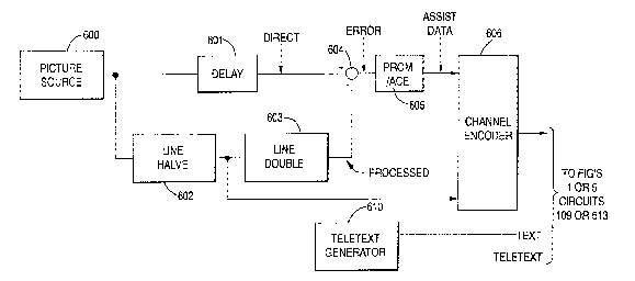
Referring now to Figure 6, apparatus is shown for providing
an auxiliary input signal to either decision-making circuit 109 of
Figure 1 or circuit 513 of Figure 5. At a point in the video
transmission chain between the picture source 600, for example, at
a television studio, and a signal encoder 606 for formatting and
multiplexing or encoding a signal for transmission toward a
receiver, an error signal generator 601-605 is provided for
generating an error signal ERROR from an actual and simulated
progressively scanned high resolution video signal. Line halver
circuit 602 halves the output of picture source 600 while a line
doubler 603 according to the present invention (Figure 1 or 5)
simulates the output of the present scan conversion. Delay 601
compensates for delay in circuits 602 and 603. At combiner 604 an
ERROR signal is generated related to the difference between the
source image and the simulated (processed) image output of doubler
603. According to a look-up table 605 a one or two bit assist data
stream is generated for a block of video signal for transmission.
Desirably such an error signal ERROR is a data signal indicative of
the probability of motion in a predetermined block of video data.
- z~
- 14 -
The predetermined block of video data is preferably
horizontally wider than vertically long, for example, sixteen pixels
wide by eight lines vertically. The reason for this is to use data
which reflects changes in vertical direction with greater precision
than changes in horizontal direction.
The output ASSIST DATA of error signal generator 601-605
may, for example, be a single bit indicator of whether there is
more likely a dynamic or a static image within this block. If the
output comprises two bit messages, the signal may provide a coded
signal in which one value may identify a clearly static image and
the other three values an indication of the probability of motion.
Signal encoder 606 may comprise, for example, an auxiliary
data transmission on a separate data channel (in band or out-of-
band) of a cable television system or a B-type multiplexed analog
components satellite signal encoder. In the latter case, a 19.2
kilobit assist data signal may be alternatively transmitted on one of
four or six audio channels. Upon receipt by circuits 109 or 513 the
error signal data stream may assist or may even preempt analysis
of the received video signal.
Furthermore, signal encoder 606 may be designed in
accordance with copending application Serial No. 255, 31~, filed
concurrently herewith entitled "High Definition B-MAC Television
Signal Transmission System" of Keith Lucas incorporated herein by
reference. In accordance with that application, signal encoder 602
provides a horizontal resolution improvement of the video signal
while the present invention improves vertical resolution.
Consequently, the inventions compliment one another when applied
in a direct broadcast satellite system.
At or near the location of the receiver or in connection with
transmission of a teletext signal for display with a transmitted
dynamic video signal, teletext generator 610 may provide a
preemptive signal TEXT which may correspond to a teletext
character or a predetermined block of characters or portion of an
image or a frame for display. The frame, frame portion or
character is displayed for the period of time or duration of output
z~ct~
-- 15 --
signal teletext and so a static image provided for such image
portion. In this manner, the signal TEXT forces data for line c or e
to be displayed and so preempts any other selectable alternative.
Alternatively, if the image portion is a predetermined size such as
the size of a teletext character, the signal teletext without an
auxiliary signal TEXT will preempt a choice of value c or e for
element d.