Note: Descriptions are shown in the official language in which they were submitted.
2000302
--1--
ROTATABLE ARTICULATED MERCHANDISE DISPLAY UNIT
SPECIFICATION
The present invention relates to a rotatable
merchandise display unit for displaying various types
of merchandise, such as for instance greeting cards and
the like, and more particularly relates to a rotatable
display unit having a plurality of generally vertical
rows of radially extending merchandise receiving pockets
or structures, disposed in generally lateral relationship
with respect to one another around an articulated column
structure rotatable with respect to a central support
wherein the column structure and mounted row of merchan-
dise receiving pockets are adapted to undulate or pivot
with respect to one another during rotation of the
column and pockets about the central support.
BACKGROUND OF THE INVENTION
Many types of article display units or
merchandise fixtures are well known in the prior art,
and many types of rotatable display units, convention-
ally called or referred to as "spinner type" displayunits, are known. Spinner type display units generally
consist of a rotatable column or columns, on which
are mounted merchandise display shelves or trays,
with the shelves or trays having upwardly facing pockets
for receiving and displaying merchandise therein, such
as for instance greeting cards, or other types of mer-
chandise. These shelves or trays do not usually move
relative to one another during rotation of the display
unit about its vertical axis.
SUMMARY OF THE INVENTION
The present invention provides a rotatable
merchandise display u nit of the aforementioned "spin-
ner type" but wherein the merchandisereceiving trays or
shelves can undulate, or pivot, relative to one another
during rotation of the shelves about the central sup-
port of the display unit, thereby providing for better
2000302
--2--
viewing of the merchandise disposed in the pockets of
trays, but also presenting unique attention-getting
motion during rotation of the display unit.
Accordingly it is an object of the present
5 invention to provide a novel rotatable type merchandise
display unit or fixture.
Another object of the invention is to provide a
merchandise display unit of the aforementioned type
which comprises a generally central support projecting
10 upwardly from a base and supporting vertically elon-
gated articulated column structure in rotatable rela-
tion thereon and with a plurality of generally verti-
cally oriented rows of merchandise receiving pockets
or trays disposed along the column, with cam means
15 on the inner sides of the column coacting with the
central support, and providing for the rows of
merchandise receiving pockets to undulate or pivot with
respect to one another during rotation of the column
structure and mounted merchandise receiving trays, about
20 the central support.
Another object of the invention is to provide
a merchandise display unit of the aforementioned type,
wherein the column structure is of polygonal configura-
tion in plan, with the sides of the polygonal configura-
25 tion being hinged to one another for relative pivotalmovement therebetween during rotation of the column
structure about the central support, thus resulting in
the specified undulating or pivotal movement of the
merchandise receiving pockets or trays of the display
30 unit with respect to one another, during said rotation.
A still further object of the invention is
to provide a merchandise display unit of the afore-
mentioned type wherein the rows of merchandise receiving
pockets or trays consist of members disposed in gener-
35 ally stacked relationship and which are removably
~ 2000302
coupled to the articulated column by coacting trackand wing means.
A still further object of the invention is to
provide a merchandise display unit of the aforemen-
5 tioned type wherein the merchandise receiving trays areformed of translucent or transparent plastic so that
the merchandise in each tray pocket is visible through
the retaining sidewalls thereof.
A still further object of the invention is to
10 provide a merchandise display unit of the aforemen-
tioned type wherein the rotatable column of the unit
is formed of vertically elongated webs hinged to one
another to form a column structure having in plan a
generally hexagonal configuration, in one reposed con-
15 dition of the column.
BRIEF DESCRIPTION OF THE DRAWINGS
FIGURE 1 is a generally perspective, eleva-
tional view of a merchandise display unit or "spinner"
embodying the invention;
FIGURE 2 is a generally perspective view of
the merchandise display unit of FIGURE 1 taken from
another elevational angle thereof;
FIGURE 3 is an enlarged, fragmentary, perspec-
tive view of the upper end portion of the display unit
25 of FIGURES 1 and 2 (with the header of the display unit
deleted), illustrating the hinged arrangement of
support column disposed around a central support, and the
preferably removable relationship of the merchandise
receiving trays as mounted on tracks on the rotatable
30 support column;
FIGURE 4 is a fragmentary, enlarged top plan
illustration, showing the polygonal configuration
of the rotatable articulated column structure, and the
4 - 2000302
outwardly projecting relationship of the merchandise
receiving trays with respect to such column structure;
the coupling elements hinging the sides of the column
structure together, having been sectioned;
FIGURE 5 is a view similar to FIGURE 4, but
showing the positional relationship of the hinged sides
of the column structure with respect to one another
after the side walls of the column and the associated
receiving trays have moved in undulating or pivotal fash-
ion with respect to one another and to a different posi-
tion, and as the result of the turning or rotation of
the articulated column and associated trays, on the cen-
tral support of the display unit.
FIGURE 6 is a fragmentary, generally diagram-
matic top perspective view of the column and associatedmerchandise receiving trays mounted thereon, with the
arm and cam structure of the rotatable column projecting
inwardly from each inner side of the column structure
and engaging a hub secured to or formed to the central
support, for supporting the column structure and asso-
ciated merchandise receiving trays, on the central support,
for rotation with respect thereto; one of the hinge
bracket members which hinges the sides of the column
together, is illustrated in exploded condition from its
respective adjacent sides of the column;
FIGURE 7 is a fragmentary, perspective, bot-
tom view of the column and associated merchandise re-
ceiving trays as mounted on the central support, and
showing the engagement of the lower cams or glides of
the column with the lower hub of the central support,
for rotatable mounting of the column and associated
merchandise receiving trays, on the central support;
the trays are illustrated in a raised condition, from
2000302
their normal positions, in the interests of clarity
of illustration of the lower cam or glide structure.
FIGURE 8 is a fragmentary, elevational, per-
spective view of the display unit, illustrating the
glide structure of FIGURE 7, taken from a different
- view thereof, to show the supporting relationship of
such structure on the column and with respect to a
lower hub of the central support;
FIGURE 9 is an enlarged top plan illustra-
tion of one of the side members of the column thatwhen hinged together form the articulated column;
FIGURE 10 is a broken, side elevational view
of the column side member shown in FIGURE 9, taken
from the righthand side thereof;
15FIGURE 11 is an enlarged, side elevational
view of one of the coupling hinge elements for hinging
the column sides together into an articulated poly-
gonal shaped configuration;
FIGURE 12 is a top plan view of the coupling
hinge element of FIGURE 11;
FIGURE 13 is a bottom plan view of the coup-
ling hinge element of FIGURE 11;
FIGURE 14 is an exploded broken view of a
pair of adjacent side members of the column, showing
the assembly of the coupling hinge element of FIGURES 11
through 13 with the column side members, to hinge the
column side members together;
FIGURE 15 is a reduced size, generally dia-
grammatic top plan view of the display unit illustrated
in FIGURES 4 and 6; and
FIGURE 16 is a reduced size, generally dia-
grammatic bottom view of the display unit taken gen-
erally along the plane of line 16-16 of FIGURE 7, looking
in the direction of the arrows.
-6- 2000302
DE~CRIPTION OF PREFERRED EMBODIMENT
Referring now again to the drawings and
particularly to FIGURES 1 and 2 thereof, there is
illustrated a "spinner type" portable, merchandise
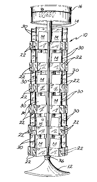
5 display unit 10 embodying the invention, and comprising
in the embodiment illustrated, a base 12 having a gen-
erally vertical, central support or post 14 extending
upwardly therefrom, with a header structure 16 mounted
on the upper end of the central support 14 and adapted
10 to have advertising indicia shown thereon, promoting
the merchandise M displayed by unit 10.
Rotatably mounted on and supported by the
central support 14 is an elongated column 18 (FIGURE 3)
which comprises a polygonal shaped structure in plan
15 (FIGURES 4 and 5) including side members 19 which are
hinged or coupled to one another at their adjacent
edges, so that the side members 19 can pivot or hingedly
move relative to one another during rotation of the
column structure 18 about the central support 14.
Merchandise receiving trays 22 are mounted
on a respective side member 19 of the column, and in
the embodiment illustrated are removably mounted, so
as to project generally radially outwardly from the
respective side member 19 and thus move or undulate
25 relative to one another during the hinged movement of
the side members of the column, relative to one another
upon rotation of the column about support 14.
Each of the side members 19 in the embodi-
ment illustrated, has inwardly projecting flanges re-
30 presenting track structure 24 on its outer face, adja-
cent its side edges, and each tray 22 preferably has
wing structure 26 (FIGURES 4 and 5) at its inner end,
which is received in the track structure 24 of the
respective side member, so as ~ slidably mount the
35 respective merchandise receiving tray 22 on its re-
spective side member, and as aforementioned in radially
~7~ 2000302
projeeting relation to the respeetive side member.
Eaeh of the merehandise reeeiving trays 22
eomprises, in the embodiment illustrated, a reeeptaele 28
(FIG. 3) having a generally eentral web 30 projecting
5 upwardly therefrom and dividing the receptaele into
lateral merehandise reeeiving seetions 28a, 28b, which
are adapted to reeeive therein merchandise, such as
for instanee, greeting eards.
The bottom wall of receptacle 28 preferably
10 slopes downwardly and outwardly as at 31 from the cen-
tral web 30, as best seen in FIGURE 3, and thus by
gravity, urges the merchandise M in the trays outwardly
toward the exterior respective side wall of the recep-
taele 28. Sueh sloping bottom wall sections 31 pro-
15 vides a recess extending lengthwise of the reeeptacle,which is adapted to reeeive therein the eentral web 30
on the underlying receptacle, and thus position and
stack the merchandise reeeiving trays relative to one
another in vertieally oriented, laterally spaced rows
20 on the column, and providing the "spinner" strueture
illustrated in FIGURES 1 and 2. Merehandise reeeiving
trays 22 are preferably formed of translueent or trans-
parent material, sueh as for instanee aerylie plastic,
so that the merchandise can be generally viewed through
25 the tray strueture.
Eaeh of the eolumn side members 19 in the
embodiment illustrated, eomprises a generally vertieally
extending elongated web portion 32 and an arm portion 32a
extending inwardly from the web portion 32 in the direc-
30 tion of the central support 14, with a circular (in theembodiment illustrated) cam 32b being provided on the
distal end of arm 32a, adapted for engagement with a
collar 34 (FIGURES 6 and 15) whieh is mounted on and
preferably secured to the central support 14.
-8- 2000302
Cammed arms 32a engage the collar for supporting or
mounting the column 18 on the central support 14, with
the column being rotatably movable relative to the
collar 34, during rotation of the column 18 on central
support 14.
The lower end of the central support 14 gener-
ally adjacent base 12 may also include a collar struc-
ture 36 (FIGURES 7 and 8) preferably secured to support 14,
and which collar provides a generally horizontal sur-
face 36a, which provide a support for glides or cams 37attached to the underside of the respective arm 32a of
each side of the column 18, with such glides 37 engag-
ing surface 36a and aiding in supporting the hinged
column 18 and associated merchandise trays 22 on the
central support 14, in movable relation thereto. Glides 37
may be and preferably are formed of some low resistance
material, such as for instance, nylon plastic, for ease
of movement with respect to surface 36a, upon rotation
of the column and associated merchandise receiving trays
about the central support.
Referring now in particular to FIGURES 9 through
14, there is shown in detail the hinge bracket members 38,
used to hinge one side member 19 to the adjacent member 19,
to form the hinged column structure 18.
Hinge bracket member 38 comprises, in the em-
bodiment illustrated, a generally horizontally oriented
base portion 38a with a generally circular in transverse
cross section, male projection 38b extending from the
base portion 38a in generally perpendicular relation-
ship with respect thereto, and with a plurality of
generally deformable or yieldable finger portions 38c
likewise projecting from the base portion 38a, in
generally parallel relationship to the axis of the
2000302
cylindrical-like male projection 38b. Bracket 38 is
preferably formed of moldable or castable material, and
as best seen in FIGURE 14 is assemblable with the re-
spective adjacent side members 19 of the column 18 and
on the upper and lower ends thereof for hinging the ad-
jacent side members together.
In this connection, each side member 19 has
a circular opening or passageway 40 formed therein
generally adjacent a vertical edge thereof, adapted to
receive in relatively rotatable relation the aforemen-
tioned male projection 38b on the respective hinge brack-
et 38, and adjacent the other vertical edge thereof, is
provided with a non-circular opening 42, which is adapted
to receive therein in generally wedging relationship the -
deformable fingers 38c of an associated hinge bracket, forsecuring the bracket 38 in the associated opening 42,
and thus hinging the pair of adjacent side members 19 of
the column together. In this connection, it will be seen
that the opening 42 is non-circular in plan, generally
D configuration in plan in the embodiment illustrated
(FIGURE 9) including a generally flat defining surface 42a
and a generally curved defining surface 42b, and that
the finger structure 38c likewise represents a generally
D-like configuration, in plan, substantially complemen-
tary to opening 42 for wedging relation therein. Trans-
verse structure3gc~ of finger 38c is adapted for generally
flat surface-to-surface engagement with complementary
surface 42a of opening 42 while the other radially ex-
tended finger sections of finger structure 38c project
outwardly from the transverse portion and in the general
direction of the cylindrical pivot portion 38b of the
hinge bracket 38, thus securing the hinge bracket to
its respective mounting side member 19 and yet providing
2o00302
--10--
for pivotal movement of the adjacent side member rela-
tive to the respective side member (via the receipt of
the cylindrical male portion 38b within the opening 40
in such adjacent side member 19 and as shown in FIGURE 14.
As can be best seen in FIGURES 11-13, the
bracket 38 may be provided with a hub portion 46 on its
underside, from which the finger structure 38c projects,
and which causes commencement of the projection of the
fingers at a lower elevation (as viewed in FIGURE 11) as
10 compared to the commencement of projection of the cylin-
drical male portion 38b, thus insuring that the pivotal
or hinged side 19 is not engaged tightly between the
base portions 38a of the respective pair of upper and
lower brackets pivoting the adjacent side member 19 to
15 the respective side member, when the cylindrical male
portions 38b of the upper and lower hinge brackets are
received in the respective receiving opening 40 therein,
thus maintaining a non-binding hinged relationship between
the pair of adjacent hinged side members 19.
Referring to FIGURES 4 and 5, it will be
understood that applying a counterclockwise force to
right hand side of tray A (as illustrated in FIGURE 4)
causes tray A to rotate counterclockwise around the
center of its cam 32b as a pivot point. During this
25 movement, the cam remains essentially on the same
radius r of center support 14.
Simultaneously, tray B moves along an arcuate
path generating a compound motion, one component of
which moves the tray inwardly toward support 14 while
30 another component moves the tray counterclockwise
around a vertical axis through the center of support 14.
Throughout its travel along the described arcuate path,
the tray is retained in an essentially rectilinear
relationship with diameter d through the center of
2000302
- -lOa-
support 14. Thus, the inner and outer ends of the tray
remain parallel to diameter d and its sides remain
perpendicular to diameter d (compare FIGURES 4 and 5).
In the course of this arcuate movement of
5 tray B, its associated cam 32b slides downwardly (with
reference to FIGURES 4 and 5) along the peripheral
surface of collar 34, and in the direction of cam 32b
associated with tray C.
Trays C and E undergo the identical motion
10 described above for tray A; and trays ~ and F undergo
the identical motion described above for tray B.
FIGURE 5 shows the configuration of the trays
at the far reach of the above-described motion. Contact
between pairs of cam 32b brings the motion program to
15 an end.
~ Once the stage depicted in FIGURE 5 is
reached, the application of additional force to the
right hand side of tray A will cause all six trays to
move in tandem, in a circular path around a vertical
20 axis through the center of support 14.
Returning to FIGURE 4, if a clockwise force
is applied to the left hand side of tray A, the above-
described motion program will be conducted in reverse.
Tray A will rotate clockwise around its cam 32b as a
25 pivot point. Tray F will move along an arcuate path
while essentially maintaining its rectilinearity with
respect to a fixed diameter through the center of support
14. However, instead of cam 32b associated with trays
A and F being in contact at the far reach of the
30 motion (see FIGURE 5) tray A's cam 32b will be in
contact with cam 32b associated with tray B, and tray
F's cam 32b will be in contact with cam 32b associated
with tray E.
2000302
-lOb-
The FIGURE 5 configuration can be returned
to the FIGURE 4 configuration by either (a) applying
a clockwise force to the side of tray C closer to
tray D, or the side of tray A closer to tray B, or
5 the side of E closer to tray D; or (b) applying a
counterclockwise force to the side of tray D closer
to tray C, or the side of tray B closer to tray A,
or the side of tray F closer to tray E.
Operation of the merchandise display unit may
10 be as follows: When a purchaser wants to view further of
the merchandise disposed in the trays 22, he will turn
the unit by pushing or applying rotative force to the
outwardly projecting trays, causing rotation of the
column 18 and attached merchandise trays about the
15 central support 14. If the hinged column and
associated tray structure are in the position shown
in FIGURE 4, wherein the column 18 (in plan) defines a
generally hexagonal configuration, application of rotary
force to the trays and associated column by the customer
20 will cause turning of the column and assorted trays on
the central support 14, will cause the side members 19
forming the column 18 to pivot or move with respect to
one another and to a position illustrated in FIGURE 5,
wherein the column 18 defines, in plan, a generally
25 triangular shape configuration. During such hinged
movement, the side members 19 will pivot or move
relative to one another about the male projecting
portions 38b, and the cam portions 32b disposed on
the inwardly projecting arms 32a of each side
30 member 19 forming the column structure 18, will
2000302
--ll--
move relative to the collar 34 into the position
illustrated, for instance, in FIGURE 5 wherein the
cam portions 32b have moved into generally abutting
engagement with respect to one another.
If the customer again applies a rotative
force to the outwardly projecting trays and hinged
column structure, the hinged column side member
structure 19 and associated trays will move again
relative to one another, to, for instance, back to
lO the position shown, for instance, in FIGURE 4 or
some other intermediate position. It will be seen
therefore, that the column side members and
associated vertical rows of merchandise display
trays 22 undulate or pivot with respect to one
15 another during application of rotative force to
the column and tray structure by the customer, the
latter causing rotary movement of the column and
associated merchandise display trays about the
central support 14.
This novel undulating movement of the
hinged sides of the column and associated merchandise
display trays, relative to one another, provides a
unique appearance to the display unit as it is
rotated about the central support, as well as
25 providing for excellent observation of the merchandise
disposed in the merchandise display trays.
From the foregoing description and accompany-
ing drawings it will be seen that the invention provides
a novel rotatable, merchandise display unit comprising
30 a generally vertical central support, supporting a
2000302
-12-
vertically elongated column-like structure thereon and
in rotatable relation therewith, with the column being
formed of hinged side members and having a plurality
of generally vertical rows of merchandise receiving trays
disposed along the plural sides of the column in lateral-
ly spaced relation with respect to one another, with each
of the rows of trays providing pockets or receptacles
for receiving therein merchandise for display, and with
the display unit being so constructed and arranged that
lO the merchandise receiving tray structure and side members
forming the associated supporting column structure undu-
late or pivot with respect to one another during rotation
of the column structure and associated tray structure
about the central support.
The invention also provides a merchandise display
unit of the aforementioned type wherein the rows of mer-
chandise receiving tray members are comprised of tray
members disposed in generally stacked relationship,
which are removably coupled to the hinged column.
The invention also provides a rotatable merchan-
dise display unit of the aforementioned type wherein the
tray structure is removably coupled to the hinged column
structure by means of coacting wing and track structure.
The terms and expressions which have been used
25 are used as terms of description and not of limitation,
and there is no intention in the use of such terms and
expressions of excluding any equivalents of any of the
features shown or described, or portions thereof, and it
is recognized that various modifications are possible
30 within the scope of the invention claimed.