Language selection

Search

Patent 2000506 Summary

Third-party information liability

Some of the information on this Web page has been provided by external sources. The Government of Canada is not responsible for the accuracy, reliability or currency of the information supplied by external sources. Users wishing to rely upon this information should consult directly with the source of the information. Content provided by external sources is not subject to official languages, privacy and accessibility requirements.

Claims and Abstract availability

Any discrepancies in the text and image of the Claims and Abstract are due to differing posting times. Text of the Claims and Abstract are posted:

  • At the time the application is open to public inspection;
  • At the time of issue of the patent (grant).
(12) Patent Application: (11) CA 2000506
(54) English Title: VEHICLE WHEEL
(54) French Title: ROUE POUR VEHICULE
Status: Deemed Abandoned and Beyond the Period of Reinstatement - Pending Response to Notice of Disregarded Communication
Bibliographic Data
(51) International Patent Classification (IPC):
  • B06B 01/06 (2006.01)
  • B60B 01/00 (2006.01)
  • B60B 05/02 (2006.01)
(72) Inventors :
  • HOPKINS, MARK WILLARD (United States of America)
  • PRINCIPE, FRANK SANTO (United States of America)
(73) Owners :
  • E. I. DU PONT DE NEMOURS AND COMPANY
(71) Applicants :
  • E. I. DU PONT DE NEMOURS AND COMPANY (United States of America)
(74) Agent: MARKS & CLERK
(74) Associate agent:
(45) Issued:
(22) Filed Date: 1989-10-11
(41) Open to Public Inspection: 1990-04-12
Examination requested: 1996-09-19
Availability of licence: N/A
Dedicated to the Public: N/A
(25) Language of filing: English

Patent Cooperation Treaty (PCT): No

(30) Application Priority Data:
Application No. Country/Territory Date
258,312 (United States of America) 1988-10-12

Abstracts

English Abstract


TITLE
Vehicle Wheel
ABSTRACT OF THE DISCLOSURE
A wheel formed of a rim joined to a hub
by a multi-spoke foam structure that is coated with
a fiber reinforced resin material is defined by
particular relationships between the spokes and the
radiused sections joining the spokes to the hub and
the rim.
D.51
CD-2290


Claims

Note: Claims are shown in the official language in which they were submitted.

Claims
What is claimed is:
1. A wheel comprising: a circular
member, a hub concentric with said circular member,
and a plurality of elongated spokes connected
between said hub and said circular member, each of
said spokes having a leading and a trailing edge,
an aerodynamic profile, and an aspect ratio greater
than about 3.0 throughout its length.
2. The wheel as defined in claim 1, said
circular member having an aerodynamic shaped
leading edge directed toward said hub and in aspect
ratio greater than about 2.6.
3. The wheel as defined in claim 1
wherein said aspect ratio of the spoke is about
3.8.
4. The wheel is defined in claim 2
wherein the aspect ratio of the circular member is
about 2.9.
5. The wheel as defined in claim 2
wherein the spokes are joined to the circular
member by radiused sections having a radius that is
about equal to one-half the width of the spoke.
6. The wheel as defined in claims 1, 2,
3, 4 or 5 wherein said wheel is formed of a foam
core coated with a fiber reinforced resin material.
7. The wheel as defined in claim 6
wherein said resin is a thermosetting resin, said
fiber being carbon fiber.
8. The wheel as defined in claim 2
wherein the spoke is joined to the hub by radiused
sections having a radius that is about equal to the
width of the spoke.
9. The wheel as defined in claims 1, 2,
3, 4 or 5 wherein there are three spokes.
CD-2290

10. The wheel as defined in claim 6
wherein said fiber is glass.
11. The wheel as defined in claim 6
wherein said fiber is a combination of carbon and
glass fibers.
12. The wheel as defined in claim 6
wherein said fiber is an aramid fiber.
13. The wheel as defined in claim 6
wherein said fiber is a blend of carbon, glass,
polyethylene, extended chain polyethylene and
aramid fibers.
14. The wheel as defined in claim 1
wherein the surface of said wheel has a surface
finish less than about 16 rms.
15. The wheel as defined in claim 6
wherein said fiber is polyethylene.
16. The wheel as defined in claim 6
wherein the fiber is extended chain polyethylene.

Description

Note: Descriptions are shown in the official language in which they were submitted.


5~
1
CD-2290
TITLE
Vehicle Wheel
Background of the Invention
This invention relates to a vehicle wheel
and, more particularly, to a fiber reinforced
multi-sp~ke ~icycle wheel for use on a standard
commercial bicycle frame.
In recent years the sport of bicycle
racing has grown dramatically. Nith this growth
has come an increased desire for a ~ompetitive
advantage. Racers are constantly seeking new ways
to go faster.
In 1983, Francesco Moser used a bicycle
with two disc wheels to set a new world speed
record ~or the ~port of bicycle racing. The disc
wheel offers a lower wind resistance than a
state-of-the-art spoked wheel. ~owever' the disc
wheels, especially when used as a front wheel,
present a problem in controlling the bicycle when
they are hit with a crosswind or a gust from a
passing automobile. This, of course, can be
alleviated by using a spoked wheel; however, prior
art spoked wheels have a drag factor that results
in less than satisfactory performance under racing
conditions
Summary of the Invention
i~; In order to overcome the difficulty
experienced with crosswinds and reduce the drag
force encountered with prior known spoked wheels,
a wheel has been developed that comprises a
circular member, a hub and a plurality of elongated
spokes connected between the hub and the circular
member. Each of the spokes is defined by an
aerodynamic profile and a width to thickness aspect
ratio of greater than 3.0 (preferably about 3.8).
~`
~ : 1
,
.
:~ ,

5~
The circular member which is capped by a rim has an
aerodynamically shaped leading edge directed toward
the hub and a width to thickness aspect ratio
greater than 2.6 (preferably about 2.9). The
spokes, preferably three, having equal shapes and
dimensions and spaced at 120 intervals emanate
radially from the hub and at one end are joined to
the hub by radiused sections that have a radius
about equal to the width of a spoke. At the other
end the spokes are joined to the circular member by
radiused sertions that have a radius about equal to
~ne-half the width of a spDke.
Preferably the wheel has a foam core
covered with a fiber reinforced resin having a
surface finish less then 16 rms. Suitable resins
can be either thermosetting or thermoplastic
resins. The reinforcing fiber can be carbon,
glass, aramid, polyethylene, extended chain
polyethylene or various combinations thereof.
~rief Description of the Drawings
Fig. 1 is a side elevational view of a
Vehicle Wheel showing my new design.
Fig. 2 is an end elevational view of the
same.
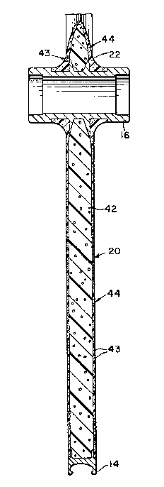
Fig. 3 is a cross-sectional view taken
along line 3-3 of Fig. 1.
Fig. 4 is a cross-sectional view taken
along line 4-4 of Fig. 1.
Fig. 5 is a cross-sectional view taken
along line 5-5 of Fig. 1.
Detailed Description of the Preferred Embodi~ent
Referring to the drawings, the wheel 10
chosen for purposes of illustration includes a
circular member 12 capped with rim 14, a hub 16 and
three radial spokes 18, 20 and 22 connecting the
hub 16 to the circular me ber 12. Each of the
.~
.
'

00~ql;6
spokes has a leading and trailing edge designated
by the individual spoke element number followed by
a or b, respectively. For example, #poke lB has a
leading edge 18a and a trailing edge 18b. Each
spoke is defined by an aerodynamic profile as best
seen in Fig. 5 and has equivalent lengths 1, widths
w and maximum thickness t, The spokes are each
further defined as having an aspect ratio which is
the ratio of width w to maximum thickness t of
greater than 3.0 throughout ~he length 1 of the
spoke. ~he circular member 12 has an
aerodynamically shaped leading edge 12a and an
aspect ratio which is the ratio of width w~ to
thickness t' (Fig. 4~ of greater than about 2.6.
The spokes are joined to the circular member 12 by
radiused sections 30, 32, 34, 36, 38 and 40, each
having a radius that is about equal to one-half the
width w of a spoke. In the same manner the spokes
are joined to the hub 16 by radiused sections 24,
26 and 2B, each having a radius that is about equal
i to the width w of the spokes.
The wheel is defined by a foam core 42
attached to the hub 16 and the rim 14 coated with
resin layer 44 that is reinforced with fibers 43.
2~ In a series of wind tunnel tests
simulating cross wind conditions at normal racing
speeds, wheels made according to the invention were
; found to have a surprisingly low drag and exhibited
stable handling when installed on a bicycle.
In the preferred embodiment illustrated
in Figs. 1-5, the spokes have a curved profile
represented by a substantial portion of an air foil
profile of the type disclosed in the Theory of Wing
Sections Including a Summary of Airfoil Data by
I. H. Abbott and A. E. Von Doenhoff. Dover
'

5~16
Publications (pages 312-379) which is incorporated
herein by re~erence.
Example
An aluminum rim and an aluminum hub
similar to those shown in Figs. 1-5 are positioned
in a foam core mold having a configuration capable
of forming the wheel ~hown in Figs. 1-5. The h~b
is placed concentric with the rim. Adhesive (605
by Adteck Company) was applied to the surfaces of
the rim and hub which contact the foam to insure
good bonding. A eommercial grade polyurethane
XRS-~705 purchased ~rom Rubicon Chemical i~
injected into the mold. The foam expands and bonds
to the rim and hub and i6 allowed to cure at 140F
for 15 minutes. The molded foam wheel is removed
from the mold.
Six piece6 of carbon fiber fabric ~3K
plain weave, 5 oz./sq. yd., style N342 from North
American Textile) are cut to fit over the molded
foam. Each piece was large enough to cover
recesses in the hub and rim and the exposed foam.
Four pieces of the fabric are cut in a way that the
fibers are oriented at + 45 to the long direction
of one of the spokes. The other two layers are cut
so that the warp fibers are parallel to the long
~- direction of the spoke~ Next, identical stacks,
each containing three layer6 of fabric, are made,
one for each side of the wheel. In ~ach stack the
layer of fabric next to the foam is oriented so
that the fibers are placed at 1 45 to the long
direction of a spoke. In the next layer of fabric
the warp fibers are oriented parallel to the same
spoke. The third layer is oriented in the same
direction as the first with the fibers at ~ 45 to
the ~poke. The ~tacks are placed against the
wheel, one on earh clde. A carbon Eiber veil (I
:
.' ,

5C~6
.
oz./sq. yd.) wa6 wrapped around each spoke and
metal staples are used to keep the veil and fabric
attached to the foam core. Last, a nylon thread is
wrapped around the rim to keep the fabric and veil
firmly against the foam core.
An adhesive ~605 by Adteck) is applied to
the surfaces of the aluminum hub which are to come
in contact with the carbon fabric. Next, the
carbon fabric is placed on each side of the molded
foam wheel, resin ~Dow 530 vinyl ester resin
system) is poured in the bGttom of the mold,
Srickling it out over as much of the mold as
possible. The molded foam three spoked wheel with
fabric attached is placed into the mold and resin
is trickl`ed on top Gf the wheel. The mold is
closed and resin (stored at room temperature) is
pumped into the mold for about six minutes at 10-20
psi inlet pressure. The mold temperature is
180-200F. The wheel is allowed to cure in the
mold for thirty minutes. Then the wheel is removed
from the mold, deflashed and sanded until smooth.
The aspect ratio of the spokes and the rim was 3078
and 2.87, respectively.
.

Representative Drawing
A single figure which represents the drawing illustrating the invention.
Administrative Status

2024-08-01:As part of the Next Generation Patents (NGP) transition, the Canadian Patents Database (CPD) now contains a more detailed Event History, which replicates the Event Log of our new back-office solution.

Please note that "Inactive:" events refers to events no longer in use in our new back-office solution.

For a clearer understanding of the status of the application/patent presented on this page, the site Disclaimer , as well as the definitions for Patent , Event History , Maintenance Fee  and Payment History  should be consulted.

Event History

Description Date
Inactive: IPC from MCD 2006-03-11
Time Limit for Reversal Expired 1999-10-12
Application Not Reinstated by Deadline 1999-10-12
Deemed Abandoned - Failure to Respond to Maintenance Fee Notice 1998-10-13
Inactive: Status info is complete as of Log entry date 1998-04-16
Inactive: Application prosecuted on TS as of Log entry date 1998-04-16
Request for Examination Requirements Determined Compliant 1996-09-19
All Requirements for Examination Determined Compliant 1996-09-19
Application Published (Open to Public Inspection) 1990-04-12

Abandonment History

Abandonment Date Reason Reinstatement Date
1998-10-13

Maintenance Fee

The last payment was received on 1997-09-03

Note : If the full payment has not been received on or before the date indicated, a further fee may be required which may be one of the following

  • the reinstatement fee;
  • the late payment fee; or
  • additional fee to reverse deemed expiry.

Patent fees are adjusted on the 1st of January every year. The amounts above are the current amounts if received by December 31 of the current year.
Please refer to the CIPO Patent Fees web page to see all current fee amounts.

Fee History

Fee Type Anniversary Year Due Date Paid Date
Request for examination - standard 1996-09-19
MF (application, 8th anniv.) - standard 08 1997-10-14 1997-09-03
Owners on Record

Note: Records showing the ownership history in alphabetical order.

Current Owners on Record
E. I. DU PONT DE NEMOURS AND COMPANY
Past Owners on Record
FRANK SANTO PRINCIPE
MARK WILLARD HOPKINS
Past Owners that do not appear in the "Owners on Record" listing will appear in other documentation within the application.
Documents

To view selected files, please enter reCAPTCHA code :


To view images, click a link in the Document Description column. To download the documents, select one or more checkboxes in the first column and then click the "Download Selected in PDF format (Zip Archive)" or the "Download Selected as Single PDF" button.

List of published and non-published patent-specific documents on the CPD .

If you have any difficulty accessing content, you can call the Client Service Centre at 1-866-997-1936 or send them an e-mail at CIPO Client Service Centre.


Document
Description 
Date
(yyyy-mm-dd) 
Number of pages   Size of Image (KB) 
Abstract 1990-04-11 1 14
Claims 1990-04-11 2 54
Drawings 1990-04-11 2 59
Representative Drawing 1990-04-11 1 15
Descriptions 1990-04-11 5 175
Courtesy - Abandonment Letter (Maintenance Fee) 1998-11-09 1 184
Correspondence 1993-07-28 10 451
Fees 1991-09-24 2 93
Fees 1996-09-04 1 83
Fees 1995-09-19 1 76
Fees 1994-09-05 1 65
Fees 1992-09-08 1 78
Fees 1993-09-02 1 60