Note: Descriptions are shown in the official language in which they were submitted.
A METHOD FOR FOR~ING A METAL MATRlX COMPOSIT~ BODY
BY AN OUTSIDE-IN SPONTANEOUS INFILTRATION
PRQCESS, AND PROD~CT~ PRODUC~D THEREBY
Field of the Invention
The present invention relates to a novel method for
forming metal matrix composites, and products produced
thereby. Particularly, a permeable mass of filler
S material is }ormed into a preform, the preform containing
a cavity in at least a portion thereof. An infiltration
enhancer and/or an infiltration enhancer precursor and/or
an infiltrating atmosphere are also in communication with
the preform, at least at some point during the process,
which permits molten matrix metal to spontaneously
infiltrate the preform when the preform is placed into
molten matrix metal. The infiltrating atmosphere should
communicate at least with the cavity in the preform for at
least a portion of the process. Moreover, when molten
matrix metal is contacted with an exterior portion of the
preform, the molten matrix metal will spontaneously
infiltrate the preform from an exterior surface thereof
toward the cavity therein.
Background of the Invention
Composite products comprising a metal matrix and a
strengthening or reinforcing phase such as ceramic
particulates, whiskers, fibers or the like, show great
promise for a variety of applications because they combine
~5 some of the stiffness and wear resistance of the
reinforcing phase with the ductility and toughness of the
metal matrix. Generally, a metal matrix composite will
show an improvement in such properties as strength,
stiffness, contact wear resistance, and elevated
temperature strength retention relative to the matrix
metal in monolithic form, but the degree to which any
given property may be improved depends largely on the
7~
-- 2
specific constituents, their volume or weight fraction,
and how they are processed in forming the composite. In
some instances, the composite also may be lighter in
~ weight than the matrix metal per se. Aluminum matrix
.~ composites reinforced with ceramics such as silicon
carbide in particulate, platelet, or whisker form, for
example, are of interest because of their higher
stiffness, wear resistance and high temperature strength
relative to aluminum.
Various metallurgical processes have been described
for the fabrication of aluminum matrix composites,
including methods based on powder metallurgy techniques
and liquid-metal infiltration techniques which make use of
pressure casting, vacuum casting, stirring, and wetting
agents. With powder metallurgy techniques, the metal in
the form of a powder and the reinforcing material in the
form of a powder, whiskers, chopped fibers, etc., are
admixed and then either cold-pressed and sintered, or
hot-pressed. The maximum ceramic volume fraction in
silicon carbide reinforced aluminum matrix composites
produced by this method has been reported to be about 25
volume percent in the case of whiskers, and about 40
volume percent in the case of particulates.
The production of metal matrix composites by powder
metallurgy techniques utilizing conventional processes
2~ imposes certain limitations with respect to the
characteristics of the products attainable. The volume
fraction of the ceramic phase in the composite is limited
typically, in the case of particulates, to about 40
percent. Also, the pressing operation poses a limit on
the practical size attainable. Only relatively simple
product shapes are possible without subsequent processing
(e.g., forming or machining) or without resorting to
complex presses. Also, nonuniform shrinkage during
sintering can occur, as well as nonuniformity of
2~
-- 3
microstructure due to segregation in the compacts and
grain growth.
U.S. Patent No. 3,970,136, granted July 20, 1976, to
J. C. Cann~ll et al., describes a process for forming a
metal matrix composite incorporating a fibrous
reinforcement, e.g. silicon carbide or alumina whiskers,
having a predetermined pattern of fiber orientstion. The
composite is made by placing parallel mats or felts of
coplanar fibers in a mold with a reservoir of molten
matrix metal, e.g., aluminum, between at least some of the
mats, and applying pressure to force molten metal to
penetrate the mats and surround the oriented fibers.
Molten metal may be poured onto the stack of mats while
being forced under pressure to flow between the mats.
Loadings of up to about 5~% by volume of reinforcing
fibers in the composite have been reported.
The above-described infiltration process, in view of
its dependence on outside pressure to force the molten
matrix metal through the stack of fibrous mats, is subject
to the vagaries of pressure-induced flow processes, i.e.,
possible non-uniformity of matrix formation, porosity, etc.
Non-uniformity of properties is possible even though
molten metal may be introduced at a multiplicity of sites
within the fibrous array. Consequently, complicated mat/
2~ reservoir arrays and flow pathways need to be provided to
achieve adequate and uniform penetration of the stack of
fiber mats. Also, the aforesaid pressure-infiltration
method allows for only a relatively low reinforcement to
matri~ volume fraction to be achieved because of the
difficulty inherent in infiltrating a large mat volume.
Still further, molds are required to contain the molten
metal under pressure, which adds to the expense of the
process. Finally, the aforesaid process, limited to
infiltrating aligned particles or fibers, is not directed
to formation of aluminum metal rnatrix composites
- 4
reinforced with materials in the form of randomly oriented
particles, whiskers or fibers.
In the fabrication of aluminum matrix-alumina filled
composites, aluminum does not readily wet alumina, thereby
making it difficult to form a coherent product. Various
solutions to this problem have been suggested. ~ne such
approach is to coat the alumina with a metal (e.g., nickel
or tungsten), which is then hot-pressed along with the
aluminum. In another technique, the ~lùminum is alloyed
with lithium, and the alumina may be coated with silica.
However, these composites exhibit variations in
properties, or the coatings can degrade the filler, or the
matrix contains lithium which can affect the matrix
properties.
U.S. Patent No. 4,232,091 to R. W. Grimshaw et al.,
overcomes certain difficulties in the art which are
encountered in the production of aluminum matrix-alumina
composites. This patent describes applying pressures of
75-375 kg/cm2 to force molten aluminum (or molten aluminum
alloy) into a fibrous or whisker mat of alumina which has
been preheated to 700 to 1050C. The maximum volume ratio
of alumina to metal in the resulting solid casting was
0.25/1. Because of its dependency on outside force to
accomplish infiltration, this process is subject to many
of the same deficiencies as that of Cannell et al.
European Patent Application Publication No. 115,742
describes making aluminum-alumina composites, especially
useful as electrolytic cell components, by filling the
voids of a preformed alumina matrix with molten aluminum.
The application emphasizes the non-wettability of alumina
by aluminum, and therefore various techniques are employed
to wet the alumina throughout the preform. For example,
the alumina is coated with a wetting agent of a diboride
of titanium, zirconium, hafnium, or niobium, or with a
metal, i.e., lithium, magnesium, ~alcium, titanium,
- 5
.
chromium, iron, cobalt, nickel~ zirconium, or hafnium.
~:~ Inert atmospheres, such as argon, are employed to
facilitate wetting. This reference also shows applying
pressure to cause nnolten aluminurn to penetrate an uncoated
S matrix. In this aspect, infiltration is accomplished by
evacuating the pores and then applylng pressure to the
.~ molten aluminum in an inert atmosphere, e.g., argon.
Alternatively, the preform can be infiltrated by
vapor-phase aluminum deposition to wet the surface prior
to filling the voids by infiltration with molten aluminum.
- To assure retention of the aluminum in the pores of the
; preform, heat treatment, e.g., at 1400 to 1800C, in
either a vacuum or in argon is required. Otherwise,
either exposure of the pressure infjltrated material to
gas or removal of the infiltration pressure will cause
loss of aluminum from the body.
The use of wetting agents to effect infiltration of
an alumina component in an electrolytic cell wi~h molten
metal is also shown in European Patent Application
Publication No. 94353. This publication describes
production of aluminum by electrowinning with a cell
having a cathodic current feeder as a cell liner or
substrate. In order to protect this substrate from molten
cryolite, a thin coating of a mixture of a wetting agent
and solubility suppressor is applied to the alumina
substrate prior to st~rt-up of the cell or while immersed
in the molten aluminum produced by the electrolytic
process. Wetting agents disclosed are titanium,
zirconium, hafnium, silicon, magnesium, vanadium,
chromium, niobium, or calcium, and titanium is stated as
the preferred agent. Compounds of boron, carbon and
nitrogen are described as being useful in suppressing the
solubility of the wetting agents in molten aluminurn. The
reference, however, does not suggest the production of
metal matrix composites, nor does it suggest the formation
7~
-- 6
of such a composite in, for example, a nltrogen
atmosphere.
In addition to application of pressure and wetting
agents, it has been disclosed that an applied vacuum will
S aid the penetration of molten aluminum into a porous
ceramic compact. For example, U.S. Patent No. 3,718,441,
granted February 27, 1973, ~o R. L. Landingham, reports
infiltration of a ceramic compact (e.g., boron carbide,
alumina and beryllia) with either molten aluminum,
beryllium, magnesium, titanium, vanadium, nickel or
chromium under a vacuum of less than 10-6 torr. A vacuum
of 10-2 to 10-~ torr resulted in poor wetting of the
ceramic by the molten metal to the extent that the metal
did not flcw freely into the ceramic void spaces.
However, wetting WRS said to have improved when the vacuum
was reduced to less than 10-6 torr.
~ .S. Patent No. 3,864,154, granted February 4, 1975,
to G. E. Gazza et al., also shows the use of vacuum to
achieve infiltration. This patent describes loading a
cold-pressed compact of AlB12 powder onto a bed of cold-
pressed aluminum powder. Additional aluminum was then
positioned on top of the AIB12 powder compact. ~he
crucible, loaded with the AIB12 cornpact "sandwiched"
between the layers of r~luminum powder, was placed in a
vacuum furnace. The furnace was evacuated to
approximately 10-5 torr to permit outgassing. The
temperature was subsequently raised to llOO~C and
maintained for a period of 3 hours. At these conditions,
the molten aluminum penetrated the porous AIB12 compact.
U.S. Patent No. 3,364,976, granted January 23, 1968
to John N. Reding et al., discloses the concept of
creating a self-generated vacuum in a body to enhance
penetration of & molten metal into the body.
Specifically, it is disclosed thst a body, e.g., a
graphite mold, a steel mold, or a porous refractory
- 7
material, ls entirely submerged in a molten metal. In the
case of a mold, the mold cavity, which is filled with a
gas reactive with the metal, comnunicates with the
externally located molten metal through at least one
orifice in the mold. When the mold is immersed into the
melt, filling of the cavity occurs as the self-generated
; vacuum is produced from the reaction between the gas in
the cavity and the molten metal. Parti~ularly, the vacuum
is a result of the formation of a solid oxidized form of
the metal. Thus, Reding et al. disclose that it is
essential to induce a reaction between gas in the cavity
and the molten metal. However, utilizing a mold to create
a vacuum may be undesirable because of the inherent
limitations associated with use of a mold. Molds must
first be machined into a particular shape; then finished,
machined to produce an acceptable casting surface on the
mold; then assembled prior to their use; then disassembled
after their use to remove the cast piece therefrom; and
thereafter reclaim the mold, which most likely would
include refinishing surfaces of the mold or discarding the
mold if it is no longer acceptable for use. Machining of
a mold into a complex shape can be very costly and
time-consuming. Moreover, removal of a formed piece from
a complex-shaped rnold can also be difficult (i.e., cast
pieces having a complex shape could be broken when removed
from the mold). Still further, while there is a
suggestion that a porous refractory material can be
immersed directly in a molten rnetal without the need for a
mold, the refractory material would have to be an integral
piece because there is no provision for infiltrating a
loose or separated porous material sbsent the use of a
container mold (i.e., it is generally believed that the
particulate material would typically disassociate or float
apart when placed in a molten metal). Still further, if
it was desired to infiltrate a particulate material or
7~
loosely formed preform, precautions should be taken so
that the infiltrating metal does not displace at least
portions of the particulate or preform resulting in a
non-homogeneous microstructure.
Accordingly, there has been a long felt need for a
simple and reliable process to produce shaped metal matrix
composites which does not rely upon the use of applied
pressure or vacuum (whether externally applied or
internally created), or damaging wetting agents to create
a metal matrix embedding another material such as a
ceramic material. Moreover, there has been a long felt
need to minimize the amount of final machining operations
needed to produce a metal matrix composite body. The
present invention satisfies these needs by providing a
spontaneous infiltration mechanism for infiltrating a
material le.g., a ceramic material), which can be formed
into a preforml with molten matrix metal (e.g., aluminum)
in the presence of an infiltrating atmosphere (e.g.,
nitrogen) under normal atmospheric pressures so long as an
infiltration enhancer is present at least at some point
during the process.
Description of Commonl~ Owned U.S. Patent Applications
The subject matter of this application is related to
that of several other copending and co-owned patent
applications. Particularly, these other copending patent
applicaticns describe novel methods for making metal
rnatrix composite materials (hereinafter sometimes referred
to as "Commonly Owned Metal Matrix Patent Applications").
A novel method of making a metal m~trix composite
material is disclosed in Commonly Owned U.S. Patent
Application Serial No. 049,171, filed May 13, 1987, in the
names of White et al., and entitled "Metal Matrix
Composites", now allowed in the United States. According
to the method of the White et al. invention, a metal
Z~ 79~
g
matrix composite is produced by infiltrating a permeable
mass of filler material ~e.g., a ceramic or a
ceramic-coated material) with molten aluminum containing
at least about 1 percent by weight magnesium, ~nd
preferably at least about 3 percent by weight magnesium.
Infiltr~tion occurs spontaneously without the application
of external pressure or vacuum. A supply of the molten
metal alloy is contacted with the mass of filler material
at a temperature of at least about 675C in the presence
of a gas comprising from about 10 to 100 percent, and
preferably at least about 50 percent, nitrogen by volume,
and a remainder of the gas, if any, being a nonoxidizing
gas, e.g., argon. ~nder these conditions, the molten
aluminum alloy infiltrates the ceramic mass under normal
atmospheric pressures to form an aluminum (or aluminum
alloy) matrix composite. ~hen the desired amount of
filler material has been infiltrated with the molten
aluminum alloy, the temperature i5 lowered to solidify the
alloy, thereby forming a solid metal matrix structure that
embeds the reinforcing filler material. Usually, and
preferably, the supply of molten alloy delivered will be
sufficient to pPrmit the infiltration to proceed
essentially to the boundaries of the mass of filler
material. The amount of filler material in the aluminum
~5 matrix composites produced according to the White et al.
invention may be exceedingly high. In this respect,
filler to alloy volumetric ratios of greater than 1:1 may
be achieved.
Under the process conditions in the aforesaid White
et al. invention, aluminum nitride can form as a
discontinuous phase dispersed throughout the aluminum
matrix. The amount of nitride in the aluminum matrix may
vary depending on such factors as temperature, alloy
composition, gas composition and filler material. Thus,
by controlling one or more such factors in the system, it
- 10 -
is possible to tailor certain properties of the composite.
For some end use applications, however, it may be
desirable that the composite contain little or
substantially no aluminum nitride.
lt has been observed that higher temperatures favor
infiltration but render the process more conducive to
nitride formation. The White et al. invention allows the
choice of a bal~nce between infiltration kinetics and
nitride formation.
An example of suitable barrier means for use with
metal matrix composite formation is described in Comnonly
Owned and Copending U.S. Patent Application Serial No.
141,642, filed January 7, 1988, in the names of Michael K.
Aghajanian et al., and entitled "Method of Making Metal
Matrix Composite with the use of a Barrier". According to
the method of this Aghajanian et al. invention a barrier
means (e.g., particulate titanium diboride or a graphite
material such as a flexible graphite tape product sold by
Union Carbide under the trade narne Grafoil~) is disposed
on a defined surface boundary of a filler material and
matrix alloy infiltrates up to the boundary defined by the
barrier means. The barrier means is used to inhibit,
prevent, or terminate infiltration of the molten alloy,
thereby providing net, or near net, shapes in the
resultant metal matrix composite. Accordingly, the forme~
metal matrix composite bodies have an outer shape which
substantiAlly corresponds to the inner shape of the
barrier means.
The method of U.S. Patent Application Serial No.
049,171 was improved upon by Commonly Owned and Copending
U.S. Patent Application Serial No. 168,284, filed March
15, 1988, in the n~mes of Michael K. Aghajanian and Marc
S. Newkirk and entitled "Metal Matrix Composites and
Techniques for Making the Same." In accordance with the
methods disclosed in this U.S. Patent Application, a
26~ 7~
- 11 -
matrix metal alloy is present as a first source of metal
and as a reservoir of matrix metal alloy which
comnunicates with the first source of molten metal due to,
for example, gravity flow. Particularly, under the
conditions described in this patent application, the first
source of molten m~trix alloy begins to infiltrate the
mass of filler material under normal atmospheric pressures
and thus begins the formation o a metal matrix composite.
The first source of molten matrix metal alloy is consumed
during its infiltration into the mass of filler material
and, if desired, can be replenished, preferably by a
continuous means, from the reservoir of molten matrix
metal as the spontaneous infiltration continues. When a
desired amount of permeable filler has been spontaneously
infiltrated by the molten matrix alloy, the temperature i5
lowered to solidify the alloy, thereby forming a solid
metal matrix structure that embeds the reinforcing filler
material. lt should be understood that the use of a
reservoir of metal is simply one embodiment of the
invention described in this patent application and it is
not necessary to combine the reservoir embodiment with
each of the alternate embodiments of the invention
disclosed therein, some of which could also be beneficial
to use in combination with the present invention.
The reservoir of metal can be present in an amount
such that it provides for a sufficient amount of metal to
infiltrate the permeable mass of filler material to a
predetermined extent. Alternatively, an optional barrier
means can contact the permeable mass of filler on at least
one side thereof to define a surface boundary.
Moreover, while the supply of molten matrix alloy
delivered should be at least sufficient to permit
spontaneous infiltration to proceed essentially to the
boundaries (e.g., barriers) of the permeable mass of
filler material, the amount of alloy present in the
2q~ 7~
- 12 -
reservoir could exceed such sufficient amount so that not
only will there be a sufficient amount of alloy for
complete infiltration, but excess molten metal alloy could
remain and be attached to the metal matrix composite body.
Thus, when excess molten alloy is present, the reslllting
body will be a complex composite body (e.g., a
macrocomposite), wherein an infiltrated ceramic body
having a metal matrix therein will be directly bonded to
excess metal remaining in the reservoir.
~ach of the above-discussed Co~nonly Owned Metal
Matrix Patent Applications describes methods for the
production of metal matrix composite bodies and novel
metal matrix cornposite bodies which are produced therefrom.
The entire disclosures of all of the foregoing Commonly
Owned Metal Matrix Patent ~pplications are expressly
incorporated herein by reference.
Summary of the Invention
A metal matrix composite body is produced by
spontaneously infiltrating a permeable mass of filler
material which has been formed into a preform, said
preform con~aining, ~t least in a portion there~f, a
cavity. Specifically, a matrix metal is made molten and
the matrix metal is held within an appropriate
non-reactive vessel for housing matrix metal (e.g., a
suita~le refractory container) to form a body of molten
matrix metal. The preform containing the cavity can be
placed at least partially into the molten matrix metal
such that an infiltrating atnosphere can communicate with
the cavity in the preform for at least a portion of the
process, in order to obtain spontaneous infiltration of
molten matrix metal from an exterior surface of the
preform toward the cavity therein.
More specifically, an infiltration enhancer and/or
an infiltration enhancer precursor communicate with the
- 13 -
preform, at least at sorne point during the process, which
permits or in~uces molten matrix metal to spontaneously
infiltrate the preform when sn exterior surface of the
preform is placed into at least partial contact with
molten matri~ metal. Thus, molten matrix metal
infiltrates the preform from an outside surface thereof
towards the cavity, thus producing a metal matrix
composite body having substantially the geometry of the
preform.
In a preferred embodiment, an infiltrating
atmosphere is substantially continuously supplied to a
cavity or interior portion in a preform. An exterior
portion or surface of the preform is exposed to molten
matrix metal. The substantially simultaneous exposure of
the cavity in the preform to an infiltrating atmosphere
and exposure of the exterior surface of the preform to
molten matrix metal causes the molten matrix metal to
spontaneously infiltrate the preform, so long as an
infiltration enhancer precursor and/or an infiltration
enhancer are also provided to the spontaneous system in at
least one of the matrix metal and/or the preform and/or
the infiltrating atmosphere.
In a further preferred embodiment, prior to
ir~nersing in molten matrix metal a cylindrical or tubular
shaped preform which does not contain a natural cavity, a
temporary cavity is formed in the preform. Particularly,
for example, an open end of the preform which is to be
immersed into molten matrix metal can be plugged with an
appropriate plugging means. Such plugging means serves to
create a temporary cavity in the preform. Accordingly,
the temporary cavity can accept and maintain an
infiltrating atmosphere for a requisite amount of time.
The plugging means may comprise a rnaterial which is
substantially non-reactive with each of, or at least one
of, the matrix metal and/or the preform and/or the
37~
1~ -
infiltrating atmosphere and/or the infiltration enhancer
and/or the infiltration enhancer precursor. Once such a
preform includes a plugging means therein to create a
temporary cavity, molten matrix metal may spontaneously
infiltrate the preform from an exterior surface thereof
toward the temporary cavity.
In another preferred embodiment, in a naturally
formed cavity in a preform, or in a temporary cavity which
is formed by the use of a plugging means, further
includes, at another portion thereof, a restricting means
which restricts or reduces the con~unication of the cavity
in the preform with any non-infiltrating atmosphere which
may be present. Particularly, in order to create a more
confined or self-contained atmosphere within a naturally
occurring cavity or a temporary cavity, an open end of the
preform is at least partially restricted or closed so that
infiltrating atmosphere which is to flow into the cavity
is restricted from escaping and/or any non-infiltrating
atmosphere (e.g., an oxidant) may be restricted from
communi~ating with the cavity. The use of said
restricting m2ans in the preform may assist molten matrix
metal to spontaneously infiltrate the preform from an
exterior portion of the pre~orm toward the cavity in the
preform.
In a still further preferred embodiment, an oxidant
gatherer may be placed into a natural cavity in a preform
or a temporary cavity in a preform to act as a gatherer or
trapper of any solid, liquid or gaseous oxidant.
Specifically, in order to minimize the formation of
oxidation reaction product due to, for example oxidizing
impurities which may be present in the infiltrating
atmosphere or may become present in the infiltrating
atmosphere and which, if not controlled, may react with
molten matrix metal to form a reaction product, it may be
desirable to include an oxidant gatherer.
t7~
- 15 -
Thus, to obtain spontaneous infiltration, an
infiltration enhancer ~recursor or an infiltration
enhancer mny be supplied directly to at least one of the
preform, and/or matrix metal, and/or infiltrating
atmosphere. However, ultimately, at least during the
spontaneous infiltlation, the infiItration enhancer should
be located in at least a portion of the preform.
It is noted that this application discusses primarily
aluminum matrix metals which, at some point during the
formation of the metal matrix composite body, are
contacted with magnesium, which functions as the
infiltration enhancer precursor, in the presence of
nitrogen, which functions as the infiltrating atmosphere.
Thus, the matrix metal/infiltr~tion enhancer
precursor/infiltrating atmosphere system of
aluminum/magnesium/nitrogen exhibits spontaneous
infiltration. However, other matrix metal/infiltration
enhancer precursor/infiltrating atmosphere systems may
also behave in a manner similar to the system
ZO aluminum/magnesium/nitroge~. For example, similar
spontaneous infiltration behavior has been observed in the
aluminum/strontium/nitrogen system; the
aluminum/zinc/oxygen system; and the
aluminum/calcium/nitrogen system. Accordingly, even
though the aluminum/magnesium/nitrogen system is discussed
primarily herein, it should be understood that other
matrix metal/infiltration enhancer precursor/infiltrating
atmosphere systems may behave in a similar manner.
When the matrix metal comprises an aluminum alloy,
3~ the aluminum alloy is contacted with a preform comprising
a filler material ~e.g., alumina or silicon carbide
particles), said filler material having admixed therewith,
and/or at some point during the process being exposed to,
magnesium. Moreover, in a preferred embodiment, the
aluminum alloy and preform are contained in a nitrogen
~[3791~
- 16 -
atmosphere or at least a portion of the process. The
preform will be spontaneously infiltrated by the matrix
metal and the extent or rate o~ spontaneous inf91tration
and formation of metal matrix will vary with a given set
of process conditions including, for example, the
concentration of magnesium provided to the system (e.g.,
in the aluminum &l loy and/or in the preform and/or in the
infiltrating atmosphere), the size and/or composition of
the particles in the preform, the concentration of
nitrogen in the infiltrating atmosphere, the time
permitted for infiltration, and/or the temperature at
which infiltration occurs. Spontaneous infiltration
typically occurs to an extent sufficient to embed
substantially completely the preform.
Definitions
"Aluminum", as used herein, means and includes
-
essentially pure metal (e.g., a relatively pure,
commercially available unalloyed aluminum) or other grades
of metal and metal alloys such as the commercially
available metals having impurit;es and/or alloying
constituents such as iron, silicon, copper, magnesium,
manganes~, chromium, æinc, etc., therein. An aluminum
alloy for purposes of this definition is an alloy or
intermetallic compound in which aluminum is the major
constituent.
"Balance Non-Oxidizin~ Gas", as used herein, means
that any ~as present in addition to the primary gas
comprising the infiltrating atmosphere, is either an inert
gas or a reducing gas which is substant.ally non-reactive
with the matrix metal under the process conditions. Any
oxidizing gas which may be present as an impurity in the
gas(es) used should be insufficient to oxidize the matrix
metal to any substantial extent under the process
conditions.
7~
- 17 -
"Barrier" or "barrier means", as used herein, means
any suitable means which interferes, inhibits, prevents or
terminates the migration, movement, or the like, of molten
matrix metal beyond a surface boundary of a permeable mass
of Iiller material or preform, where such surface boundary
is defined by said barr9er means. Suitable barrier means
may be any such material, compound, element, composition,
or the like, ~hich, under the process conditions,
maintains some integrity and is not substantially volatile
(i.e.j the barrier material does not volatilize to such an
extent that it is rendered non-functional as a barrier).
Further~ suitable "barrier means" includes materials
which are substantially non-wettable by the migrating
molten matrix metal under the process conditions employed.
A barrier of this type appears to exhibit substantially
little or no affinity for the molten matrix metal, and
movement beyond the defined sur~ace boundary of the mass
of filler material or preform is prevented or inhibited by
the barrier means. The barrier reduces any final
machining or grinding that may be required and defines at
least a portion of the surface of the resulting metal
matrix composite product. The barrier may in certain
cases be permeable or porous, or rendered permeable by,
for example, drilling holes or puncturing the barrier, to
permit gas to contact the molten matrix metal.
"C rcass" or "Carcass of Matrix Metal", as used
herein, refers to any of the original body of matrix metal
remaining which has not been consumed during formation of
the metal matrix composite body, and typically, if allowed
to cool, remains in at least partial contact with the
metal matrix composite body which has been formed. lt
should be understood that the carcass may also include a
second or foreign metal therein.
"Cavity", as used herein, means any unfilled space
within a mass or body which either naturally occurs or is
2~
- 13 -
artificially created, and is not limited to any specific
configuration of space. Specifically, a cavity can
include those spaces which are substantially closed off
from communication to an exterior portion of the mass or
body, but still can permit comnunication with an exterior
portion of the mass or body. Moreover, a cavity includes
a non-naturally occurring (i.e., R temporary cavity)
partially closed off space in a body, which can be made
into a cavity by inserting in at least a portion of the
non-closed off space, a plugging means, which assists in
forming a temporary cavity within a body.
"Filler", as used herein, is intended to include
either single constituents or mixtures of constituents
which are substantially non-reactive with and/or of
limited solubility in the matrix metal and may be single
or multi-phase. Fillers may be provided in a wide Yariety
of forms, such as powders, flakes, platelets,
microspheres, whiskers, bubbles, etc., and may be either
dense or porous. "Filler" may also include ceramic
fillers, such as alumina or silicon carbide as fibers,
chopped fibers, particulates, whiskers, bubbles, spheres,
fiber mats, or the like, and ceramic-coated fillers such
as carbon fibers coated with alumina or silicon carbide to
protect the carbon from attack, for example, by a molten
aluminum parent metal. Fillers may also include metals.
"Infiltrating Atmosphere", as used herein, means
that ntmosphere which is present which interacts with the
matrix metal and/or preform (or filler material) and/or
infiltration enhancer precursor and/or infiltration
enhancer and permits or enhances spontaneous infiltration
of the matrix metal to occur.
"Infiltration Enhancer", as used herein, means a
: material which promotes or assists in the spontaneous
infiltration of a matrix metal into a filler material or
preform. An infiltration enhancer may be formed from, for
- 19 -
e~ample, a reaction of an infiltration enhancer precursor
with an infiltrating atmosphere to form (1) a gaseous
species and/or (2) a reaction product of the infiltration
enhancer precursor and the infiltrating atmosphere and/or
(3) a reaction product of the infiltration enhancer
precursor and the filler material or preform. Moreover,
the infiltration enhancer rnay be supplied directly to at
least one of the preform, and/or matrix metal, and/or
infiltrating atmosphere and function in a substantially
similar manner to an infiltration enhancer which has
formed as a reaction between an infiltration enhancer
precursor and another species. Ultimately, at least
during the spontaneous infiltration, the infiltration
enhancer should be located in at least a portion of the
filler material or preform to achieve spontaneous
infiltration.
"Infiltration Enhancer Precursor" or "Precursor to
the Infiltration Enhancer", as used herein, means a
material which when used in combination with the matrix
metal, preform and/or infiltrating atmosphere forms an
infiltration enhancer which induces or assists the matrix
metal to spontaneously infiltrate the filler material or
preform. Without wishing to be bound by any particular
theory or explanation, it appears as though it may be
necessary for the precursor to the infiltration enhancer
to be capable of being positioned, located or
transportable to a location which permits the infiltration
enhancer precursor to interact with the infiltrating
atmosphere and/or the preform or filler material and/or
metal. For exsmple, in some matrix metal/infiltration
enhancer precursor/infiltrating atmosphere systems, it is
desirable for the infiltration enhancer precursor to
volatilize at, near, or in some cases, even somewhat above
the temperature at which the matrix metal becomes molten.
Such volatilization may lead to: (1) a reaction of the
7~
- 20 -
infiltration enhancer precursor with the infiltrating
atmosphere to form a gaseous species which enhances
wetting of the filler material or preform by the matrix
metal; and/or (2) a reaction of the infiltration enhancer
precursor with the infiltrating atmosphere to form a
solid, liquid or gaseous infiltration enhancer in at least
a portion of the filler material or preform which enhances
wetting; and/or (3) a reaction of the infiltration
enhancer precursor within the filler material or preform
which forms a solid, liquid or gaseous iniltration
enhancer in at least a portion of the filler material or
preform which enhances wetting.
"Matrix Met=l" or "Matrix Metal Alloy", as used
herein, means that metal which is utilized to form a metal
matrix composite (e.g., before infiltration) and/or that
metal which is intermingled with a filler material to form
a metal matrix composite body (e.g., after infiltration).
When a specified metal is mentioned as the matrix metal,
it should be understood that such matrix metal includes
that metal as an essentially pure metal, a commercially
available metal having impurities and/or alloying
constituents therein, an intermetallic compound or an
alloy in which that metal is the major or predominant
constituent.
"Matrix Metal/lnfiltration Enhancer
~recursor/lnfiltratin~ Atmospher~_~ysteml' or "Spontaneous
System", as used herein, refers to that combination of
materials which exhibits spontaneous infiltration into a
preform or filler material. It should be understood that
whenever a "/" appears between an exemplary matrix metal,
infiltration enhancer precursor and infiltrating
atmosphere, the "/" is used to designate a system or
combination of materials which, when combined in a
particular manner, exhibits spontaneous infiltration into
a preform or filler material.
- 21 -
"Metal Matrix Composite" or "MMC", as used herein,
means a material comprising a two- or three-dimensionally
interconnected alloy or matrix metal which has embedded a
preform or filler materisl. The matrix metal may include
various alloying elements to provide specifically desired
mechanical and physical properties in the resulting
composite.
A Metal "Different" from the Matrix Metal means a
metal which does not contain, as a primary constituent,
the same metal as the matrix metal (e.g., if the primary
constituent of the matrix metal is aluminum, the
"different" metal could have a primary constituent of, for
example, nickel).
"Non-lnfiltrating Atmosphere", as used herein, means
that atmosphere which may or may not interact with the
matrix metal and/or p.eform (or filler material) and/or
infiltration precursor and/or infiltration enhancer, but
which does not p~rmit or enhance, and which may even
inhibit, spontaneous infiltration of the matrix metal to
occur
"Nonreactive Vessel for Housing Matrix Metal" means
any vessel which can house or contain molten matrix metal
under the process conditions ~nd not react with the matrix
and/or the infiltrating atmosphere and/or infiltration
enhancer precursor and/or filler material or preform in a
manner which would be significantly detrimental to the
spontaneous infiltration mechanism.
"Oxidant Gatherer"7 as used herein, means any
suitable material (e.g., titanium metal chips) which when
used in combination with the matrix metal/infiltration
enhancer/infiltrating atmosphere under the process
conditions for spontaneous infiltration may be used to
gather or trap any solid, liquid or gaseous oxidant
present in the reaction systern which would inhibit
spontaneous infiltration of the matrix metal into the
7~l
- 22 -
filler material or preform. Preferably, the oxidant
gatherer will not react substantially with any components
in the spontaneous system in a manner which substantially
deleteriously affects spontaneous infiltration under the
process conditions.
"Plu~in~ ns" or "P~", as used herein, means
any material which can be utilized in ~ombination with a
preform which assists in crea~ing within the preforrn a
temporary cavity. Preferably, the plugging means will not
react with any components in the spontaneous system in a
manner which substantially deletereously affects
spontaneous infiltration under the process conditions.
The plugging means may or may not be removable from the
preform after infiltration of the preform. Moreover, the
~lugging means may be infiltrated by molten matrix metal
to form an integral part of the preform.
"Preform" or "Permeable Preform", as used herein,
means a porous mass of filler or filler material which is
manufactured with at least one surface boundary which
essentially defines a boundary for infiltrating matrix
metal, such mass retaining sufficient shape integrity and
green strength to provide dimensional fidelity prior to
being infiltrated by the matrix metal. The mass should be
sufficiently porous to accommodate spontaneous
infiltration oi the matrix metal thereinto. A preform
typically comprises a bonded array or arrangement of
filler, either homogeneous or heterogeneous, and may be
comprised of any suitable material (e.g., ceramic and/or
metal particulates, powders, fibers, whiskers, etc., and
any combination thereof). A preform may exist either
singularly or as an assemblage.
"Reservoir", as used herein, means a separate body
of matrix metal positioned relative to a mass of filler or
a preform so that, when the metal is molten, it may flow
to replenish, or in some cases to initially provide and
- 23 -
subsequently replenish, that portion, segment or source of
matrix metal which is in contact with the filler or
preform.
"Restriction Means" or "Restrictin~ Means", as used
herein, means any material which can be used in
combination with a preform which assists in restricting
the exit flow of infiltrating atmosphere from a cavity in
a preform and/or which restricts or reduces the
com~nunication of the cavity in the preform with any
non-infiltrating atmosphere which may be present.
Preferably, restricting means do not react with any
components in the spontaneous system which may result in a
substantial deleterious effect upon spontaneous
infiltration.
"Spontaneous Infiltration" as used herein means
the infiltration of matrix metal into the permeable mass
of filler or preform occurs without requirement for the
application of pressure or vacuum (whether externally
applied or internally created).
"Temporarv CavitY", as used herein, means a cavity
created by a plugging means, such cavity being
non-naturally occurring in the preform and which exists
only so long as the plugging means remains in contact with
the preform.
Brief Description of the Figures
The following Figures are provided to assist in
understanding the invention, but are not intended to limit
the scope of the invention. Similar reference numerals
have been used wherever possible in each of the Figures to
denote like components, wherein:
~ igure 1 is a schematic cross-section of an
assemblage of materials utilized to obtain an outside-in
infiltration of a preform;
7~
- 2~ -
Figure 2 is a schematic cross-section of an
assemblage of materials utilized to obtain an outside-in
infiltration of a preform;
Figure 3 is a schematic cross-section of an
assemblage of materials utili~ed to obtain an outside-in
infiltration of a preform;
Figure 4 is a schematic cross-section of an
assemblage of materials utilized in accordance with
Example 1;
Figure 5a is a photograph taken from a side view of
the metal matrix composite produced in accordance with
Example l; and
Figure 5b is a photograph taken from a top view of
the metal matrix composite produced in accordance with
Example 1.
Detailed Description of the InventiDn and Preferred
Embodiments
The present invention relates to forming metal
matrix composite bodies by exposing a preform at least
partially to molten matrix metal. The preform contains,
in at least a portion thereof not initially in contact
with molten matrix metal, a cavity. Moreover, the preform
contacts, at some point during the process, at leasl one
of an infiltration enhancer and/or an in~iltration
enhancer precursor and/or an infiItrating atmosphere,
which results in molten matrix metal spontaneously
infiltrating the preform from an exterior portion thereof
toward the cavity.
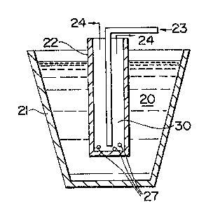
Specifically, as shown in Figure 1, a matrix metal
is made molten and the matrix metal is held within an
appropriate non-reuctive vessel for housing matrix metal
~21) (e.g., a suitable refractory container) to form a
body of rnolten matrix metal (20) . The preform (22)
containing the cavity (30) can be placed at least
7~L
- 25 -
partially into the molten matrix metal (20) such that an
infiltrating atmosphere (23) can communicate with the
cavity ~30) in the preform for at least a portion of the
process in order to obtain spontaneous infiltration of
molten matrix metal from an exterior surface of the
preform toward the cavity therein The infiltrating
atmosphere can flow out of the preform as shown by (24).
Moreover, an infiltration enhancer and/or an
infiltration enhancer precursor communicate with the
preform, at least at some point during the process, which
permits or induces molten matrix metal to spontaneously
infiltrate the preform when an exterior surface of the
preform is placed into at least partial contact with
molten matrix metal. Thus, molten matrix metal
infiltrates the preform from an outside surface thereof
towards the cavity, thus producing a metal matrix
composite body having substantially the geDmetry of the
preform.
In a preferred embodiment, an infiltrating
atmosphere is substantially continuously supplied to a
cavity or interior portion in a preform. An exterior
portion or surface of the preform is exposed (e.g., by at
least partially submerging) to molten matrix metal. The
substantially simultaneous exposure of the cavity in the
preform to an infiltrating atmosphere and exposure of the
exterior surface of the preform to molten matrix metal
causes the molten matrix metal to spontaneously infiltrate
the preform, so long as an infiltration enhancer precursor
and/or an infiltration enhancer are also provided to the
spontaneous system in at least one of the matrix metal
and/or the preform and/or the infiltrating atmosphere.
In a further preferred embodiment, prior to
exposing to molten matrix metal a cylindrical or tubular
shaped preform which does not contain a natural cavity, a
temporary cavity is formed in the preform. Particularly,
- 26 -
as shown in Figure 2, for exsmple, an open end of the
preform (22) which is immersed into molten matrix metal
(20) can be plugged with an appropriate plugging means
(25). Such plugging means (25) serves to create a
temporary cavity (30) in the preform (22). Accordingly,
the temporary cavity (30) can accept and maintain an
infiltrating atmosphere (23) for a requisite amount of
time. In a preferred embodiment, the plugging means (25)
may comprise a material which is substantially
non-reactive with each of, or at least one of, the matrix
metal (20) and/or the preform (22) and/or the infiltrating
atmosphere (23) and/or the infiltration enhancer and/or
the infiltration enhancer precursor. Once such a preform
(22) includes a plugging means (25) therein to create a
temporary cavity (303, molten matrix metal (2~) may
spontaneously infiltrate the preform (22) from an exterior
surface thereof toward the temporary cavity (30).
In another preferred embodiment, the plugging means
(25) can be chosen so that it not only serves its purpose
of creating a temporary cavity (30), but it also may be
spontaneously infiltrated by molten matrix metal (20). ln
this case, the plugging means (25) becomes an integral
part of the metal matrix composite body.
In another preferred embodiment, a naturally formed
cavity in a preform, or a temporary cavity which is formed
by the use of a plugging means, further includes, in a
portion thereof, a restricting means which restricts or
reduces the communication of the cavity in the preform
with any non-infiltrating atmosphere which may be present.
Particularly, as shown in Figure 3, in order to create a
more confined or self-cGntained atmosphere within a
naturally occurring cavity (30) or a temporary cavity
(30), an open end of the preform (22) is at least
partially restricted or closed by a restricting means (26)
so that infiltrating atmosphere (23) which is to flow into
- 27 -
the cavity (30) is restricted from escaping and/or any
non-infiltrating atmosphere (e.g., an oxidant) may be
restricted from communicating with the cavity. The use of
said restricting means (26) in the preform (22) may assist
molten matrix metal to spontaneously infiltrate the
preform (22) from an exterior portion of the preform
toward the cavity in the preform.
In a still further preferred embodiment, an oxidant
gatherer may be placed into a natural cavity in a preform
or a temporary cavity in a preform to act as a gatherer or
trapper vr any solid, liquid or ~aseous oxidant.
Specifically, in order to minimize the formation of
oxidation reaction product due to, for example oxidizing
impurities which may be present in the infiltrating
atmosphere or which may become present in the infiltrating
atmosphere and which, if not controlled, may react with
molten matrix metal to form a reaction product, it may be
desirable to include an oxidant gatherer in the cavity of
a preform. Accordingly, as shown in Figure 1, an oxidant
gatherer (27~ may be placed within the cavity (30).
Preferably, the oxidant gatherers will not react
substantially with any components in the spontaneous
system in a manner which substantially deletereously
affects spontaneous infiltration under the process
conditions.
Moreover, to obtain spontaneous infiltration, an
infiItration enhancer precursor or ~n infiItration
enhancer may be supplied directly to at least one of the
preform, and/or matrix metal, and/or infiltrating
atmosphere. However, ultimately, at least during the
spontaneous infiltration, the infiltration enhancer should
be located in at least a portion of the preform.
It may also be possible to expose a permeable mass
of filler material to molten matrix metal to obtain
spontaneous infiltration of the filler material.
- 28 -
Specifically, a permeable mass of filler material which
may rigidize (e.g., sinter) upon heating to form a solid
mass may be placed into a mold which is consumed (e.g.,
volatilizes or interdiffuses with matrix metal) during the
reaction to create a mold containing filler material and
having a cavity, either naturally occurring or
artificially created, therein which is exposed to an
infiItrating atmosphere.
The mold containing alloy is heated, either upon
placing it into a heated furnace containing the molten
matrix metal or in a separate step, to substantially
rigidize the permeable mass of filler material. The mold
containing the substantially rigidized f511er material is
exposed (e.g., by at least partially submerging) to molten
matrix alloy. The substantially simultaneous exposure of
the cavity in the substantially rigidized mass of fil]er
material to an infiltrating atmosphere and exposure of the
exterior of the substantially rigidized preform causes the
molten matrix metal to spontaneously infiltrate the filler
material, so long as infiltratiorl enhancer precursor
and/or infiltrating atmosphere and/or the infiltration
enhancer and/or the infiltration enhancer precursor. Once
such a filler material includes a plugging means therein
to create a temporary cavity, molten matrix metal may
.5 spontaneously infiltrate the preform from an exterior
surface ther~of toward the temporary cavity.
In order to effect spontaneous infiltration of the
matrix metal into the filler material or preform, an
infiltration enhancer should be provided to the
spontaneous system. An infiltration enhancer could be
formed from an infiltration enhancer precursor which could
be provided (1) in the matrix metal; and/or (2) in the
: filler material or preform; and/or (3) from the
infiltrating atmosphere and/or (4) from an external source
into the spontaneous system. Moreover, rather than
~'
2~7~3~
- 29 -
supplying an infiltration enhancer precursor, an
infiltration enhancer may be supplied directly to at least
one of the filler material or preform, and/or matrix
metal, and/or infiltrating atmosphere. Ultimately, at
least during the spontaneous infiltration, the
infiltration enhancer should be located in at least a
portion of the filler material or preform.
In a preferred embodiment, it is possible that the
infiltration enhancer precursor can be at least partially
reacted with thc infiltrating atmosphere such that
infiltration enhancer can be formed in at least a portion
of the filler material or preform prior to or
substantialiy simultaneously with contacting the preform
with molten matrix metal (e.g., if magnesium was the
infiltration enhancer precursor and nitrogen was the
infiItrating atmosphere, the infiItration enhancer could
be magnesium nitride which would be located in at least a
portion of the filler material or preform).
An example of a matrix metal/infiltration enhancer
precursor/infiltrating atmosphere system is the
aluminum/magnesium/nitrogen system. Specifically, an
aluminum matrix metal can be contained within a suitable
refractory vessel which, under the pr~cess conditions,
does not react with the aluminum matrix metal when the
aluminum is made molten. A filler material containing or
being exposed to magnesium, and being exposed to, at least
at some pGint during the processing, a nitrogen
atmosphere, can then be contaeted with the molten aluminum
matrix meta]. The matrix metal will then spontaneously
infiltrate the filler material or preform.
~ Under the conditions employed in the method of the
; present invention, in the case of an aluminum/magnesium/
nitrogen spontaneous infiltration system, the filler
: material or preform should be sufficiently permeable to
permit the nitrogen-containing gas to penetrate or
7~
- 30 -
permeate the filler material or preform at some point
during the process and/or contact the molten matrix metal.
Moreover, the permeable filler materi~l or preform can
accornmodate infiltration of the molten matri~ metal,
thereby causing the nitrogen-permeated filler material or
preform to be infiltrated spontaneously with molten matrix
metal to form a metal matrix composite body and/~r cause
the nitrogen to resct with an infiltration enhancer
precursor to form infiltration enhancer in the filler
material or preform and thereby resulting in spontaneous
infiItration. The extent or rate of spontRneous
infiltration and formation of the metal matrix composite
will vary with a given set of process conditions,
including ma~nesium content of the aluminum alloy,
magnesium content of the filler material or preform,
amount of magnesium nitride in the filler material or
preform, the presence of additional alloying elements
(e.g., silicon, iron, copper, manganese, chromium, zinc,
and the like), average size of the filler material (e.g.,
particle diameter), surface condition and type of filler
material, nitrogen concentration of the infiltrating
atmosphere, time permitted for infiltration and
temperature at which infiltration occurs. For example,
for infiltration of the molten aluminum matrix metal to
occur spontaneously, the aluminum can be alloyed with at
least about 1 percent by weight, and preferably at least
about 3 percent by weight, magnesium (which functions as
the infiltration enhancer precursor), based on al~oy
weight. Auxiliary alloying elements, as discussed above,
may also be included in the matrix meta] to tailor
specific properties thereof. (Additionally, the auxiliary
alloying elements may affect the minimum amount of
magnesium required in the matrix aluminum metal to result
in spontaneous infiltration of the filler material or
preform). Loss of magnesium from the spontaneous system
71~
- 31 -
due to, for example, volati~ization should not occur to
such an extent that no magnesium is present to form
infiltration enhancer. Thus, it is desirsble to utilize a
sufficient amount cf initial alloying elements to assure
thst spontaneous infiltration will not be adversely
~ffected by volatilization. Still further, the presence
of magnesium in both of the filler material or preform and
matrix metal or the filler material or preform alone may
result in a lesser required amount of magnesium to achieve
spontaneous infiltration (discussed in greater detail
later herein). The volume percent of nitrogen in the
nitrogen atmosphere also affects formation rates of the
- metal matrix composite body. Specifically, if less than
about 10 volume percent of nitrogen is present in the
atmosphere, very slow or little spontaneous infiltration
will occur. It has been discovered that it is preferable
for at least about 50 volume percent of nitrogen to be
present in the atmosphere, thereby resulting in, for
example, shorter infiltration times due to a much more
rapid rate of infiltration. The infiltrating atmosphere
(e.g., a nitrogen-containing gas) can be supplied directly
to the Iiller material or preform and/or matrix metal, or
it may be produced or result from a decomposition of a
material.
The minimum magnesium content required for molten
matrix nmetal to infiltrate a filler material or preform
depends on one or more variables such as the processing
temperature, time, the presence of auxiliary alloying
elements such as silicon or zinc, the nature of the filler
material, the location of the magnesium in one or more
components of the spontaneous system, the nitrogen content
of the atmosphere, and the rate at which the nitrogen
atmosphere flows. Lower temperatures or shorter heating
times can be used to obtain complete infiltration as the
magnesium content of the alloy and/or preform is increased.
- 32 -
Also, for a given magnesium content, the addition of
certain auxiliary alloying elements such as zinc permits
the use of lower temperatures. For example, a magnesium
content of the matrix metal at the lower end of the
operable range, e.g., from ~bout 1 to 3 weight percent,
may be used in conjunction with at least one of the
following: an above-minimum processing temperature, a
high nitrogen concentration, or one or more auxiliary
alloying elements. When no magnesium is added to the
filler material or preform, alloys containing ~rom about 3
to 5 weight percent magnesium are preferred on the basis
of their general utility over a wide variety of process
conditions, with at least about 5 percent being preferred
when lower temperatures and shorter times are employed.
Magnesium contents in excess of about 10 percent by weight
of the aluminum alloy may be employed to moderate the
temperature conditions required for infiltration. The
magnesium content may be reduced when used in conjunction
with an auxiliary alloying element, but these elements
serve an auxiliary function only and are used together
with at least the above-specified minimum amount of
magnesium. For example, there was substantially no
infiltration of nominally pure aluminum alloyed only with
10 percent sili~on at 1000C into a bedding of 500 mesh,
39 Crystolon (99 percent pure silicon carbide from Norton
- Co.). However, in the presence of magnesium, silicon has
been found to promote the infiltrstion process. As a
. further example, the amount of magnesium varies if it is
, supplied exclusively to the preform or filler material.
:- 30 It has been discovered that spontaneous infiltration will
: occur with a lesser weight percent of magnesium supplied
to the spontaneous system when at least some of the total
amount of magnesium supplied is placed in the preform or
filler material. It may be desirable for a lesser amount
of magnesium to be provided in order to prevent the
- 33 -
formation of undesirable intermetallics in the metal
matrix composite body. In the case of a silicon carbide
preform, it has been discovered that when the preform is
contacted with an aluminum rnatrix metal, the preform
containing at least about 1 percent by weight magnesium
and being in the presence oE a substantially pure nitrogen
atmosphere, the matrix metal spontaneously infiltr~tes the
preform. In the case of ~n alumina preform, the amount of
magnesium required to achieve acceptable spontaneous
infiltration is slightly higher. Specifically, it has
been found that when an alumina preform, when contacted
with a similar aluminum matrix metal, at about the same
temperature as the aluminum that infiltrated into the
silicon carbide preform, and in the presence of the same
nitrogen atmosphere, at least about 3 percent by weight
magnesium may be required to achieve similar spontaneous
infiltration to that achieved in the silicon carbide
preform discussed immediately above.
It is also noted that it is possible to supply to
the spontaneous system infiltration enhancer precursor
and/or infiltration enhancer on a surface of the alloy
and/or on a surface of the preform or filler material
- and/or within the preform or filler material prior to
infiltrating the matrix metal into the filler material or
preform (i.e., it may not be necessary for the supplied
; infiltration enhancer or infiltration enhancer precursor
to be alloyed with the matrix metal, but rather, simply
supplied to the spontaneous system). If the magnesium was
applied to R surface of the rnatrix metal it may be
preferred that said surface should be the surface which is
closest to, or preferably in contact with, the permeable
mass of filler material or vice versa; or such magnesium
could be mixed into at least a portion of the preform or
filler material Still further, it is possible that some
combination of surface application, alloying and placement
- 34 -
of magnesium into at least a portion of the preform could
be used. Such combination of applying infiltration
enhancer(s) and/or infiltration enhancer precursor(s)
could result in a decrease in the total weight percent of
magnesium needed to promote infiltration of the matrix
aluminum metal into the preform, as well as achieving
lower temperatures at which infiltration can occur.
Moreover, the amount of undesirable intermetallics formed
due to the presence of ~agnesium could also be minimized.
The use of one or more auxiliary alloying elements
and the concentration of nitrogen in the surrounding gas
also affects the extent of nitriding of the matrix metal
at a given temperature. For example, auxiliary alloying
elements such as zinc or iron included in the alloy, or
placed on a surface of the alloy, may be used to reduce
the infiltrat ion temperature and thereby decrease the
amount of nitride formation, whereas increasing the
concentration of nitrogen in the gas may be used to
promote nitride formation.
The concentration of magnesium in the alloy, and/or
placed onto a surface of the alloy, and/or combined in the
filler or preform material, also tends to affect the
extent of infiltration at a given temperature.
Consequently, in some cases where little or no magnesium
is contacted directly with the preform or filler material,
it may be preferred that at least about three weight
percent magnesium be included in the alloy. Alloy
contents of less than this amount, such as one weight
percent magnesium, may require higher process temperatures
or an auxiliary alloying element for infiltration. The
ternperature required to effect the spontaneous
infiltration process of this invention may be lower: (l)
when the magnesium content of the alloy alone is
increased, e.g. to at least about 5 weight percent; and/or
(2) when alloying constituents are mixed with the
- 35 -
permeable mass of filler material or preform; and/or ~3)
when another element such as zinc or iron is present in
the aluminum alloy. The temperature also may vary with
different filler materials. In general, spontaneous and
progressive infiltration will occur at a process
temperature of at least about 675C, and preferably a
process temperature of at least about 750C-800C.
Temperatures generally in excess of 1200C do not appear
to benefit the process, and ~ particularly useful
temperature range has been found to be from about 675C to
about 1200C. However, as a general rule, the spontaneous
infiltration temperature is a temperature which is above
the melting point of the matrix metal but below the
volatilization temperature of the matrix metal. Moreover,
the spontaneous infiltration temperature should be below
the melting point of the filler material. Still further,
as temperature is increased, the tendency to form a
reaction product between the matrix metal and infiltrating
atmosphere increases (e.g., in the case of aluminum matrix
metal and a nitrogen infiltrating atmosphere, aluminum
nitride may be formed). Such reaction product may be
desirable or undesirable based upon the intended
;application of the metal matrix composite body.
Additionally, electric resistance heating is typica]ly
`25 used to achieve the iniiltrating temperatures. However,
any heating means which can cause the matrix metal to
become molten and does not adversely affect spontaneous
infiltration, is acceptable for use with the invention.
In the present method, for example, a permeable
filler material or preform is placed into contact with
molten aluminum in the presence of, at least sometime
. during the process, a nitrogen-containing gas. The
nitrogen-containing gas may be supplied by maintaining a
continuous flow of gas into contact with at least one of
the filler material or the preform. Although the flow
'73~
- 3~ -
rate of the nitrogen-containing gas is not critical, it is
preferred that the flow rate be sufficient to prevent or
inhibit the incursion of air which can have an oxidizing
effect on the molten metal.
The method of forming a metal matrix composite is
applicable to a ~ide variety of filler materials, and the
choice of filler materials will depend on such factors as
the matrix alloy~ the process conditions, the reactivity
of the molten matrix alloy with the filler material, and
the properties sought for the final composite product.
For example, when aluminum is the matrix metal, suitable
filler materials include (a) oxides, e.g. alumina; (b)
carbides, e.g. silicon carbide; (c) borides, e.g. aluminum
dodecaboride, and (d) nitrides, e.g. aluminum nitride. If
there is a tendency for the filler material to react with
the molten aluminum matrix metal, this might be
accommodated by minimizing the infiltration time and
temperature or by providing a non-reactive coating on the
fil~er. The filler material may comprise a substrate,
such as carbon or other non-ceramic material, bearing a
ceramic coating to protect the substrate from attack or
degradation. Suitable ceramic coatings include oxides,
carbides, borides and nitrides. Ceramics wh i ch are
preferred for use in the present method include alumina
and silicon csrbide in the form of particles, platelets,
whiskers and fibers. The fibers can be discontinuous (in
chopped form) or in the form of continuous filament, such
as multifilament tows. Further, the filler material or
preform may be homogeneous or heterogeneous.
It also has been discovered that certain filler
materials exhibit enhanced infiltration relative to filler
materials by having a similar chemical composition. For
example, crushed alumina bodies made by the method
disclosed in U.S. Patent No. 4,713,360, entitled "Novel
Ceramic Materials and Methods of Making Same", which
7~
- 37 -
issued on December 15, 1g87, in the names of Marc S.
Newkirk et al., exhibit desirable infiltration properties
relative to commercially available alumina produets.
Moreover, crushed alumina bodies made by the method
disclosed in Copending and Commonly Owned AppIication
Serial No. ~19,397 entitled "Composite Ceramic Articles
and Methods of Making Same", in the names uf Marc S.
Newkirk et al, also exhibit desirable infiltration
properties relative to commerically available alumina
products. The subject matter of each of the issued Patent
and Copending Patent Application is herein expressly
incorporated by reference. Thus, it has been discovered
that complete infiltration of a permeable mass of ceramic
material can occur at lower infiltration temperatures
and/or lower infiltration times by utilizing a crushed or
comminuted body produced by the method of the
i aforementioned U.S. Patent and Patent Application.
; ~ The size and shape of the filler material can be any
that may be required to achieve the properties desired in
` 20 the composite. Thus, the material may be in the form of
particles, whiskers, platelets or fibers since
infiltration is not restricted by the shape of the filler
materi01. Other shapes such as spheres, tubules, pellets,
refractory fiber cloth, and the like may be employed. In
addition, the size of the material does not lirnit
infiltration, although a higher temperature or longer time
period may ~e needed for complete infiltration of a mass
of smaller particles than for l~rger particles. Further,
the mass of filler material (shaped into a preform) to be
infiltrated should be permeable (i.e., permeable to molten
matrix metal and to the infiltrating atmosphere)
The method of forming metal matrix composites
according to the present invention, not being dependent on
the use of pressure to force or squeeze molten matrix
metal into a preform or a mass of filler material, permits
7~1.
- 38 -
the production of substantially uniform metal matrix
composites having a high volume fraction of filler
material and low porosity. Higher volume fractions of
filler material mey be achieved by using a lower porosity
initial mass of filler material. Higher volume fractions
also may be achieved if the mass of filler i5 compucted or
otherwise densified provided that the mass is not
converted into either a compact with clo~e cell porosity
or into a fully dense structure thae would prevent
infiltration by the rnolten alloy.
It has been observed that for aluminum infiltration
and matrix formation around a ceramic filler, wetting of
the ceramic filler by the aluminum matri~ metal may be an
important part of the infiltration mechanism. Moreover,
at low processing temperatures, a negligible or minimal
amount of metal nitriding occurs resulting in a minimal
discontinuous phase of aluminum nitride dispersed in the
metal matrix. However, as the upper end of the
temperature range is approached, nitridation of the metal
is more likely to occur. Thus, the amount of the nitride
phase in the metal matrix can be controlled by varying the
processing temperature at which infiltration occurs. The
specific process temperature at which nitride formation
becomes more pronounced also varies with such factors as
the matrix aluminum alloy used and its quantity relative
to the volume of filler or preform, the ceramic material
to be infiltrated, and the nitrogen concentration of the
infiltrating atmosphere. For example, the extent of
aluminum nitride formation at a given process temperature
; 30 is believed to increase as the ability of the alloy to wet
the ceramic filler decreases and as the nitrogen
concentration of the atmosphere increases.
It is therefore possible to tailor the constituency
of the metal matrix during formation of the composite to
impart certain characteristics to the resulting product.
- 39 -
For a given system, the process conditions can be selected
to control the nitride formation. A composite product
containing an aluminum nitride phase will exhibit certain
properties which can be favorable to, or improve the
performance of, the product. Further, the temperature
range ior spontaneous infiltration with an aluminum alloy
may vary with the ceramic material used. ~n the case of
alumina as the filler material, the temperature for
infiltration should preferably not exceed about 1000C if
it is desired that the ductility of the matrix not be
reduced by the significant formation of nitride. However,
temperatures exceeding 1000C may be employed if it is
desired to produce a composite with a less ductile and
stiffer matrix. To infiltrate silicon carbide, higher
temperatures of about 1200C may be employed since the
aluminum alloy nitrides to a lesser extent, relative to
the use of alumina as filler, when silicon carbide is
employed as a filler material.
Moreover, it is possible to use a reservoir of
matrix metal to assure complete infiltration of the filler
material and/or to supply a second metal which has a
different composition from the first source of matrix
metal. Specifically, in some cases it may be desirable to
utilize a matrix metal in the reservoir which differs in
; 25 composition from the first source of matrix metal. For
example, if an aluminum alloy is us~d as the first source
of matrix metal, then virtually any other metal or metal
alloy which was molten at the processing temperature could
be used ~s the reservoir metal. Molten metals frequently
are very miscible with each other which would result in
the reservoir metal mixing with the first source of matrix
metal so long as an adequate amount of time is given for
the mixing to occur. Thus, by using a reservoir metal
which is different in cornposition than the first source of
matrix metal, it is possible to tailor the properties of
2~
- 40 -
the metal matrix to meet various operating requirements
and thus tailor the properties of the meta] matrix
composite.
A barrier means rnay also be utilized in combination
with the present invention. Specifically, the barrier
means for use with this invention may be any suitable
means which interferes, inhibits, prevents or terminates
the migration, movement, or the like, of molten matrix
alloy (e.g., an aluminum alloy) beyond the defined surface
boundary of the filler material. Suitable barrier means
may be any material, compound, element, composition, or
the like, which, under the process conditions of this
invention, maintains some integrity, is not volatile and
preferably is permeable to the gas used with the process
.. 15 as well as being capable of locally inhibiting, stopping,
interfering with, preventing, or the like, continued
~ infiltration or any other kind of movement beyond the
;~ defined surface boundary of the material or preform
filler.
Suitable barrier means includes materials which are
substantially non-wettable by the migrating molten matrix
alloy under the process conditions employed. A barrier of
this type appears to exhibit little or no affinity for the
molten matrix alloy, and movement beyond the defined
s~rface boundary of the filler material or preform is
prevented or inhibited by the barrier means. The barrier
reduces any final machining or grinding that may be
required of the metal matrix composite product. As stated
above, the barrier preferably should be permeable or
porous, or rendered permeable by puncturing, to permit the
gas to contact the molten matrix alloy.
Suitable barriers particularly useful for aluminum
rnatrix alloys are those containing carbon, especially the
crystalline allotropic form of carbon known as graphite.
Graphite is essentially non-wettable by the molten
q37~
- 41 -
aluminum alloy under the described process conditions. A
particular preferred graphite is a graphite tape product
that is sold under the trademark ~rafoil~, registered to
Union Carbide. This graphite tape exhibits sealing
characteristics that prevent the migration of molten
aluminum alloy beyond the defined surface boundary of the
filler material. This graphite tape is also resistant to
heat and is chemically inert. Grafoil~ graphite material
is flexible, compatible, conformable and resilient. It
can be made into a variety of shapes to fit any barrier
application. However, graphite barrier means may be
employed as a slurry or paste or even as a paint film
around and on the boundary of the filler material or
preform. Grafoil~ is particularly preferred because it is
in the form of a flexible graphite sheet. In usel this
paper-like graphite i5 simply formed around the filler
material or preform.
Other preferred barrier(s) fcr aluminum metal matrix
alloys in nitrogen are the transition metal borides (e.g.,
titanium diboride (TiB2)) which are generally non-wettable
by the molten aluminum metal alloy under certain of the
process conditions employed using this material. Wjth a
barrier of this typel the process temperature should not
exceed about 875CI for otherwise the barrier m~terial
becomes less efficacious and, in fact, with increased
temperature infiltration into the barrier will occur. The
transition metal borides are typi~ally in a particulate
form (1-30 microns). The barrier materials may be applied
as a slurry or paste to the boundaries of the permeable
mass of ceramic filler material which preferably is
preshaped as a preform.
Other useful barriers for aluminum metal matrix
alloys in nitrogen include low-volatile organic compounds
applied as a film or layer onto the external surface of
the filler material or preform. Upon firing in nitrogen,
7~
- 42 -
especially at the process conditions of this invention,
the organic compound decomposes leaving a carbon soot film.
The organic compound may be applied by conventional means
such as painting, spraying, dipping, etc.
Moreover, finely ground particulate materials can
function as a barrier so long as infiltration of th~
particulate material would occur at a rate which is slower
than ~he rate of infiltration of the filler material.
Thus, the barrier means may be applied by any
suitable means, such as by covering the defined surface
boundary with a layer of the barrier means. Such a layer
of barrier means may be applied by painting. dipping, silk
screening, evaporating, or otherwise applying the barrier
means in liquid, slurry, or paste form, or by sputtering a
~15 vaporizable barrier means, or by simply depositing a layer
;of a solid par~iculate barrier means, or by applying a
solid thin sheet or film of barrier means onto the defined
surface boundary. With the barrier means in place,
spontaneous infiltration substantially terminates when the
infiltrating matrix metal reaches the defined surface
boundary and contacts the barrier means.
The method of this invention provides for a
cost-effective production of metal matrix composite bodies
by the aforementioned process Particularly, the use of a
localized source of infiltrating atmosphere within the
cavity of the filler material or preform reduces the need
for more costly processing systems by allowing for
processing of composites in an open atmopshere.
Similarly, by this method, the formation of metal matrix
composite bodies may be carried out by a continuous
processing system. Moreover, the produced metsl matrix
composites have good net or near net shape capabilities.
Various demonstrations o~ the present invention are
included in the Examples imnediately following. However,
these Examples should be considered as being illustrative
26 ~ 9~
- 43 -
and should not be construed as limiting the scope of the
invent.on as defined in the appended claims.
: Example 1
;~ 5 Figure 4 shows an assembly, in cross-section, which
can be used to form a metal matrix composite body by an
outside-in infiltration precursor. Particularly, a
cylindrical preform (3) having a closed end (8) and a
cavity (9) was ormed by slip casting a slurry of 1000
grit silicon carbide (supplied by Exolon ESK Co. of
- Tonawanda, New York and sold under the name Carbolon
FlO00) around an alumina rod having a diameter of
approximately 1 1/2 inches by 6 inches long. The slurry
was subsequently dried and prefired in an air furnace at
1100C for about five hours to form a preform (3) having a
.~ wall thickness of about 5 millimeters. Titanium chips (5)
(supplied by Chem Alloy Co., lnc. and sold under the
~ designation QM4-30) were placed within the cavity (9) of
.- the preform (3). The preform ~3) was placed into contact
with a slightly modified 380.1 aluminum alloy (2)
(obtained from Belmont Metals) having a composition of
about 7.5-9.5% Si, 3.0-4.0% Cu, <2.9% Zn, <6.0% Fe, <0.5%
Mn, <0.5% Ni, <0.35% Sn, and ~bout O.i7-0.18% Mg, to which
an additional 5 weight percent magnesium was added. The
aluminum alloy was contained within a bed of wol]astonite
powder (7) (supplied by NYCO, Inc.), all of whieh was
contained in a refractory vessel (1). Wollastonite powder
(7) was used because molten aluminum does not readily wet
this material and it functions as a container for the
molten aluminum. The refrsctory vessel (1) snd its
contents were heated in an air furnace to a temperature of
Rbout 800C to render the aluminum alloy molten. A thin
coating or layer of wollastonite powder (6) was placed
onto surface of the molten alloy (2) which was not in
contact with the partially submerged preform ~3~ to
7~
- 44 -
prevent oxidation of molten alloy (2). An alumina flow
tube (4) comminuted an infiltrating atmosphere of about
99.9 percent pure nitrogen gas with the cavity (9) in the
preform (3~. Thus, a localized nitrogen gas atmosphere
was created within the cavity ~9). The tube (4) also
functioned to retain the preform (3) submerged
approximately four inches into the molten alloy (2). The
furnace was maintained at about 800C for about 2S hours.
The preform (3) was then removed from the alloy melt (2),
but remained within the furnace for about 10 hours until
the entire ~ssembly cooled to about room temperature.
The infiltrated preform (2) was removed from the
system and inspected. As shown in Figure Sa, which is a
side view of the formed rnetal matrix composite (8), the
preform was infiltrated only to a length of about 4
inches, which corresponded to the amount which the preform
(2) was immersed in the molten matrix alloy (2). Figure
5b, which is a top view of the metal matrix composite (8),
shows the cavity which existed within the preform (2).
Accordingly, it is clear from Figures 2a and 2b that the
outside-in spontaneous infiltration of molten matrix metal
into a preform provides good net or near net shape
capabilities.