Language selection

Search

Patent 2000813 Summary

Third-party information liability

Some of the information on this Web page has been provided by external sources. The Government of Canada is not responsible for the accuracy, reliability or currency of the information supplied by external sources. Users wishing to rely upon this information should consult directly with the source of the information. Content provided by external sources is not subject to official languages, privacy and accessibility requirements.

Claims and Abstract availability

Any discrepancies in the text and image of the Claims and Abstract are due to differing posting times. Text of the Claims and Abstract are posted:

  • At the time the application is open to public inspection;
  • At the time of issue of the patent (grant).
(12) Patent: (11) CA 2000813
(54) English Title: RIDDLING DEVICES OF URBAN SOLID GARBAGE
(54) French Title: DISPOSITIFS DE CRIBLAGE POUR DECHETS URBAINS SOLIDES
Status: Term Expired - Post Grant Beyond Limit
Bibliographic Data
(51) International Patent Classification (IPC):
  • B07B 01/50 (2006.01)
  • B07B 01/18 (2006.01)
  • B07B 01/22 (2006.01)
(72) Inventors :
  • CERRONI, MANLIO (Italy)
(73) Owners :
  • IMPRESA A. CECCHINI & C. S.R.L.
(71) Applicants :
  • IMPRESA A. CECCHINI & C. S.R.L. (Italy)
(74) Agent: SMART & BIGGAR LP
(74) Associate agent:
(45) Issued: 2000-08-29
(22) Filed Date: 1989-10-16
(41) Open to Public Inspection: 1990-04-14
Examination requested: 1996-10-10
Availability of licence: N/A
Dedicated to the Public: N/A
(25) Language of filing: English

Patent Cooperation Treaty (PCT): No

(30) Application Priority Data:
Application No. Country/Territory Date
48456 A/88 (Italy) 1988-10-14

Abstracts

English Abstract


Improvements of riddling devices of urban solid waste where,
outside the riddling cylinder, a few reeds, both continuous and
discontinuous, are applied, overhanging with respect to the same
riddling cylinder and of such a height which is proportional to
the dimensions of the holes, with the reeds having, preferably,
a longitudinal orientation and being they, furthermore, orthogonal
with respect to the external surface of the cylinder or being they
slightly inclined with respect to the radial direction in a
direction opposite to the direction of rotation of the riddling
cylinder.


Claims

Note: Claims are shown in the official language in which they were submitted.

-7-
THE EMBODIMENTS OF THE INVENTION IN WHICH AN EXCLUSIVE
PROPERTY OR PRIVILEGE IS CLAIMED ARE DEFINED AS FOLLOWS:
1. A filtering device comprising:
a rotating drum having longitudinal rows of
separating holes located through its outer surface; and
a plurality of plates located between the rows of
holes and extending from the outer surface of said
rotating drum, wherein some of said plates are located
continuously between the rows of holes and some of said
plates are located discontinuously between the rows of
holes.
2. A filtering device which includes a rotating drum
having longitudinal rows of separating holes located
through its outer surface, wherein the improvement
comprises a plurality of plates located between the rows
of holes and extending from the outer surface of the
rotating drum, wherein some of said plates are located
continuously between the rows of holes and some of said
plates are located discontinuously between the rows of
holes.

Description

Note: Descriptions are shown in the official language in which they were submitted.


2000813
It is known that urban solid waste has preliminarily to undergo
a volumetric separation and, then, a qualitative separation, for
it to become suitable for the necessary treatments in view of the
recycling of the recoverable part and of the elimination of the
non-recyclable part.
It is also known that the volumetric selection is usually
executed using rotating riddles, substantially made up of drums or
cylinders'whose shell has holes of various shapes and dimensions.
The drum undergoes a rotation around its longitudinal axis and,
as a result of such a rotation, the material put inside it tends
to separate according to its size. In other words, the material
having a size smaller than the dimensions of the holes goes through
them and is discharged outside, while the material whose size is
larger continues towards the free extremity of the drum for a
subsequent new riddling or its further treatment or disposal.
However, very often, in the case of urban solid trash, the

v _2_ ~ooos~3
material put into the rotating riddle contains rags, material that frays
easily, plastic film, wires and similar stretched bodies, materials which
wind around the area of the shell of the cylinder between contiguous
holes.
This winding phenomenon is determined by the fact that,
during its rotation, each cylinder cone distance sets itself in
the lowest position and, in such a position, the filament or,rather the
itl~terial that frays easily goes astride of the plate between two adjacent
holes, partly coming out through them. With the rotation of the cylinder
continuing, this material that frays easily is dragged with it and moves
from the lower area, during the rotation, to the upper area.
In this position, due to the combined effect of gravity and the
force tangential to the cylinder created by the aerodynamic effect
in the direction opposite to the direction pf rotation of the
cylinder itself, these materials have the ~.endency to re-enter inside
the cylinder. But, this does not happen only through the same hole
they had previously come out of, it also happens through the
adjacent hole, which is behind the hole of exit according to the
direction of rotation, creating some developments around the holes
and obstructing them.
In fact this phenomenon occurs mainly between holes positioned
longitudinally, while the transversal areas find themselves in
much more favourable conditions since, in such a radial direction,
the effect of the aerodynamic tangential force plays is only slight and
rags and material that frays easily have the tendency to re-enter thr~mh
the same holes of exit which, therefore, clean themselves.

zo 0 0~ ~ 3
y.
- 3 -
Experience has shown that 95$ of the winding phenomenon
between two holes occurs in the longitudinal interspaces and
only 5$ of it occurs in the circumferential spaces.
In any case, such a winding process determines a quick
and progressive clogging of the holes with a subsequent reduction
of the efficiency of riddling and a need for frequent and costly
cleaning, with considerable additional costs.
In the Italian patent No. 1 126 918 under the same-property,
an attempt has been made to avoid this inconvenience by way of
cylindric or conic collar-shaped appendices applied in correspondence
with all or part of the holes of the riddling surface and outside
the cylinder.
Notwithstanding its satisfactory results, the solution~prospected
by the said patent presents noticeable inconveniences, a few of
which are:
- A considerable cost for the making of the device, especially if,
as it is necessary, the collars are cone-shaped;
- due to the weight of the complex an appropriate design is required
for the machine which, in turn, results heavier and requires more
power installed for it to function;
- notwithstanding the conic shape of the collars, there is the
tendency to bring back into the riddling cylinder quite a good
quantity of material during the phase of crossing holes and collars;
- the fact that, especially in the urban solid waste riddling
systems, the determination of the holes dimensions requires to
proceed by subsequent approximations for each individual case,
makes any attempt to ~.mprove the riddling very_costly;

2000813
- 4 -
- furthermore, the fact that the holed surface is to be periodically
replaced due to the abrasion provoked by the material, contributes
to aggravate the problems of fixed and carrying costs.
Object of this invention is the elimination of the occurrence of
rags and/or material that frays easily winding around two contiguous
holes of a riddling cylinder, and this with simple means and without
the requirement for special cleaning operations of the same riddle.
As the invention calls for, outside the riddling cylinder a few
walls or ribs are placed orthogonally to the external surface of the
same shell and between lines of holes.
According to a preferred form of realization, the ribs are
adequately high and develop orthogonally to the external surface of
the cylinder or transversally inclined with respect to the radial
direction of the cylinder, such an inclination being oriented
contrary to the rotation direction of the riddling cylinder.
In another version, besides the longitudinal ribs, transversal
ribs can also be provided.
The invention will now be described and illustrated in one of
its favourite versions related to the drawing attached herewith,
where:
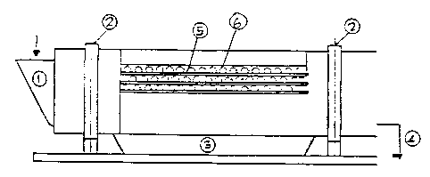
Fig. 1 shows, schematically, a rotating riddle completed with
the betterments provided by the invention;
Fig. 2 shows, schematically, a transversal vertical section of
a riddling cylinder according to the invention.
With reference to the said drawing, a riddle, according to the
invention, is made up of a cylinder (2) with holes (6) on its shell.

20 0 0~ 1 3
- 5 -
The material to riddle is introduced into the cylinder (2) through
the feedbox. The cylinder or rotor (2) is put in a spinning motion
around its longitudinal axis and the material contained in it, if
its size is lesser than the dimensions of the holes (6), goes out
of the cylinder (2) and is collected in the feedbox (3), while the
residual material goes out through the extremity of the cylinder (4).
According to the invention, the cylinder (2) is equipped
on the outside with blades (5)placed between a line of holes (6)
and the adjacent one,blades(S) which create a dial around the
cylinder, as shown in fig. 2.
Such blades(5)project to the exterior of the cylinder (2)
with a radial orientation as well as they can be slightly slanting
in a direction opposite to the direction of the rotation of the
cylinder (2). Moreover, their height is determined according tot
the holes dimensions, being of course such a height increasing
with the increase of the holes dimensions.
With the adoption of the blades (5),a self-cleaning action
of the holes (6) occurs. In fact, every rag or any material that frays
easily penetrating into two or more holes (6) placing itself astride of
them, wcuid tens tc taund..at every spin, entering and eacifi~rrqthroucrh the
holes .
The blades(5)prevent the said bodies, during the rotation of the
cylinder (2), from entering through a hole different than the one
or ones they came out from, forcing them to re-enter the riddle (2).
Since, as stated beforehand, the movement of rags and material that
frays easily is oriented by the aerodynamic force acting tangentially to
the rotor (2), it is sufficient to prevent the deviation of the

20 0 00 ~ 3
- 6 -
trajectory in this direction to obtain the desired self-cleaning
action. Therefore, with simple and economic means, we reach the
desired savings in installation and carrying expenses.
The invention has been described and illustrated only as
a non exhaustive example. Obviously it will be subject to those
variations in its realization as it will be suggested by the
specific techniques and practice without,bn the other hand,
diverting from the focus of the invention itself, as appears
from the following claims.

Representative Drawing
A single figure which represents the drawing illustrating the invention.
Administrative Status

2024-08-01:As part of the Next Generation Patents (NGP) transition, the Canadian Patents Database (CPD) now contains a more detailed Event History, which replicates the Event Log of our new back-office solution.

Please note that "Inactive:" events refers to events no longer in use in our new back-office solution.

For a clearer understanding of the status of the application/patent presented on this page, the site Disclaimer , as well as the definitions for Patent , Event History , Maintenance Fee  and Payment History  should be consulted.

Event History

Description Date
Inactive: Expired (new Act pat) 2009-10-16
Inactive: Late MF processed 2007-10-30
Letter Sent 2007-10-16
Inactive: IPC from MCD 2006-03-11
Inactive: Late MF processed 2006-01-31
Letter Sent 2005-10-17
Grant by Issuance 2000-08-29
Inactive: Cover page published 2000-08-28
Inactive: Final fee received 2000-05-19
Pre-grant 2000-05-19
Notice of Allowance is Issued 1999-11-29
Letter Sent 1999-11-29
Notice of Allowance is Issued 1999-11-29
Inactive: Application prosecuted on TS as of Log entry date 1999-11-25
Inactive: Status info is complete as of Log entry date 1999-11-25
Inactive: Approved for allowance (AFA) 1999-11-03
Inactive: Office letter 1997-10-15
Small Entity Declaration Determined Compliant 1997-10-07
Request for Examination Requirements Determined Compliant 1996-10-10
All Requirements for Examination Determined Compliant 1996-10-10
Application Published (Open to Public Inspection) 1990-04-14

Abandonment History

There is no abandonment history.

Maintenance Fee

The last payment was received on 1999-10-08

Note : If the full payment has not been received on or before the date indicated, a further fee may be required which may be one of the following

  • the reinstatement fee;
  • the late payment fee; or
  • additional fee to reverse deemed expiry.

Patent fees are adjusted on the 1st of January every year. The amounts above are the current amounts if received by December 31 of the current year.
Please refer to the CIPO Patent Fees web page to see all current fee amounts.

Fee History

Fee Type Anniversary Year Due Date Paid Date
MF (application, 8th anniv.) - small 08 1997-10-16 1997-10-07
MF (application, 9th anniv.) - small 09 1998-10-16 1998-10-08
MF (application, 10th anniv.) - small 10 1999-10-18 1999-10-08
Final fee - small 2000-05-19
MF (patent, 11th anniv.) - small 2000-10-16 2000-10-04
MF (patent, 12th anniv.) - small 2001-10-16 2001-10-01
MF (patent, 13th anniv.) - small 2002-10-16 2002-10-01
MF (patent, 14th anniv.) - small 2003-10-16 2003-10-14
2004-09-28
MF (patent, 15th anniv.) - small 2004-10-18 2004-09-28
Reversal of deemed expiry 2007-10-16 2006-01-31
MF (patent, 16th anniv.) - small 2005-10-17 2006-01-31
2006-01-31
MF (patent, 17th anniv.) - small 2006-10-16 2006-10-05
2006-10-05
MF (patent, 18th anniv.) - standard 2007-10-16 2007-10-30
Reversal of deemed expiry 2007-10-16 2007-10-30
MF (patent, 19th anniv.) - standard 2008-10-16 2008-10-09
Owners on Record

Note: Records showing the ownership history in alphabetical order.

Current Owners on Record
IMPRESA A. CECCHINI & C. S.R.L.
Past Owners on Record
MANLIO CERRONI
Past Owners that do not appear in the "Owners on Record" listing will appear in other documentation within the application.
Documents

To view selected files, please enter reCAPTCHA code :


To view images, click a link in the Document Description column. To download the documents, select one or more checkboxes in the first column and then click the "Download Selected in PDF format (Zip Archive)" or the "Download Selected as Single PDF" button.

List of published and non-published patent-specific documents on the CPD .

If you have any difficulty accessing content, you can call the Client Service Centre at 1-866-997-1936 or send them an e-mail at CIPO Client Service Centre.


Document
Description 
Date
(yyyy-mm-dd) 
Number of pages   Size of Image (KB) 
Drawings 2000-08-27 1 17
Abstract 2000-08-27 1 17
Claims 2000-08-27 1 28
Representative Drawing 2000-08-27 1 8
Descriptions 2000-08-27 6 204
Commissioner's Notice - Application Found Allowable 1999-11-28 1 164
Maintenance Fee Notice 2005-12-11 1 172
Late Payment Acknowledgement 2006-02-13 1 165
Maintenance Fee Notice 2007-11-07 1 171
Late Payment Acknowledgement 2007-11-07 1 164
Correspondence 1997-10-06 1 17
Fees 2003-10-13 1 31
Correspondence 2000-05-18 1 46
Fees 1999-10-07 1 26
Fees 1998-10-07 1 33
Fees 2002-09-30 1 32
Fees 2001-09-30 1 31
Fees 1997-10-06 2 50
Fees 2000-10-03 1 32
Fees 2004-09-27 1 31
Fees 2006-01-30 1 27
Fees 2006-10-04 1 29
Fees 2007-10-29 1 30
Fees 2008-10-08 1 35
Fees 1996-10-08 1 34
Fees 1995-10-05 1 30
Fees 1994-10-13 1 36
Fees 1994-04-12 1 50
Fees 1992-10-15 1 30
Fees 1992-11-22 1 30
Fees 1991-10-10 1 23
PCT Correspondence 1997-11-04 1 26
Prosecution correspondence 1996-10-10 2 64
Prosecution correspondence 1999-10-17 2 44
Prosecution correspondence 1999-03-24 4 94
Courtesy - Office Letter 1990-01-24 1 41
Courtesy - Office Letter 1990-12-30 1 18
Courtesy - Office Letter 1996-11-17 1 47
Examiner Requisition 1999-05-12 2 41
Examiner Requisition 1998-09-24 2 44