Language selection

Search

Patent 2001236 Summary

Third-party information liability

Some of the information on this Web page has been provided by external sources. The Government of Canada is not responsible for the accuracy, reliability or currency of the information supplied by external sources. Users wishing to rely upon this information should consult directly with the source of the information. Content provided by external sources is not subject to official languages, privacy and accessibility requirements.

Claims and Abstract availability

Any discrepancies in the text and image of the Claims and Abstract are due to differing posting times. Text of the Claims and Abstract are posted:

  • At the time the application is open to public inspection;
  • At the time of issue of the patent (grant).
(12) Patent: (11) CA 2001236
(54) English Title: FASCINE
(54) French Title: FASCINE
Status: Expired and beyond the Period of Reversal
Bibliographic Data
(51) International Patent Classification (IPC):
  • E01C 23/00 (2006.01)
  • E01C 9/08 (2006.01)
  • E01C 19/52 (2006.01)
  • F41H 7/02 (2006.01)
(72) Inventors :
  • KNIGHT, DEREK IAN (United Kingdom)
(73) Owners :
  • QINETIQ LIMITED
(71) Applicants :
(74) Agent: SMART & BIGGAR LP
(74) Associate agent:
(45) Issued: 1999-02-09
(22) Filed Date: 1989-10-23
(41) Open to Public Inspection: 1990-04-24
Examination requested: 1996-10-18
Availability of licence: N/A
Dedicated to the Public: N/A
(25) Language of filing: English

Patent Cooperation Treaty (PCT): No

(30) Application Priority Data:
Application No. Country/Territory Date
8824871 (United Kingdom) 1988-10-24

Abstracts

English Abstract


A fascine 1 suitable for filling ditches includes a core
comprising a plurality of inflatable core members 4, and a sleeve 2a
comprising a multiplicity of axially parallel sleeve members 1a
connected by at least two flexible tie means 3 such as chains. A
compressed gas cylinder 6 is provided for inflating the core, and is
connected to the core members 4 by a ring main manifold 11
incorporating one way valves for allowing gas to flow into the core
members only.
The invention also provides a plurality of fascines in
combination with a launching means.


French Abstract

Fascine (1) utilisée pour combler des fossés. La fascine inclut un noyau à plusieurs éléments gonflables (4), et une enveloppe (2a) comprenant plusieurs éléments parallèles axiaux (1a) raccordés par au moins deux dispositifs de liaison flexibles (3) comme des chaînes. Une bouteille à gaz comprimé (6) permet de gonfler le noyau, et est raccordée aux éléments (4) du noyau par un manifold principal annulaire (11) incorporant des soupapes unidirectionnelles pour permettre au gaz de s'écouler dans les éléments du noyau seulement. L'invention présente également plusieurs fascines en combinaison avec un dispositif de lancement.

Claims

Note: Claims are shown in the official language in which they were submitted.

Claims
1. A fascine including, a sleeve comprising a multiplicity of
axially parallel sleeve members transversely and continuously
connected by at least two axially spaced flexible tie means, and a
core disposed within the sleeve, wherein the core comprises a
plurality of inflatable core members.
2. A fascine as claimed in claim 1 further comprising a gas
supply means for inflating the core members.
3. A fascine as claimed in claim 2 wherein the gas supply means
comprises a source of compressed gas and a manifold connecting the
gas source to each core member.
4. A fascine as claimed in claim 3 wherein the gas source is
located in a rigid housing positioned within the fascine, so that
the gas source can be removed when the fascine is deflated.
5. A fascine as claimed in any one of claims 2 to 4 wherein the
gas supply means comprises at least one ring main manifold.
6. A fascine as claimed in any one of claims 3 to 5 wherein the
core comprises a central core member surrounded by a plurality of
surrounding core members, and the central core member is shorter
than its surrounding core members in order to accommodate at least
part of the manifold adjacent its end in such a manner that the
manifold does not project beyond the ends of the surrounding sore
members.
7. A fascine as claimed in any one of claims 3 to 6 wherein a
valve is provided for isolating the source of compressed gas from
the manifold.
8. A fascine as claimed in claim 7 wherein the valve is
remotely actuable.
9. A fascine as claimed in any one of claims 3 to 8 wherein a
one way valve is disposed between the manifold and each core member
allowing gas to flow into the core members only.
10. A fascine as claimed in any one of claims 3 to 9 wherein
each core member is individually isolatable from the manifold.

- 8 -
11. A fascine as claimed in claim 10 wherein each core
member is isolatable from the manifold by supplementary valve
means.
12. A fascine as claimed in any preceding claim wherein
each core member is provided with pressure relief means and
deflation means.
13. A fascine as claimed in any preceding claim wherein
the core members are closed inflatable tubes which are axially
parallel to the sleeve members.
14. A fascine as claimed in any preceding claim wherein
the core members have ends which do not extend beyond the
sleeve when the fascine is inflated.
15. A fascine as claimed in any preceding claim wherein
each core member contains resilient restraining means which
retract opposite ends of the core members towards each other
as the fascine is deflated.
16. A fascine as claimed in any preceding claim wherein
each core member comprises an outer casing and an air tight
inner tube.
17. A fascine as claimed in any preceding claim wherein
the core members are joined to each other.

- 8a -
18. A fascine as claimed in claim 17 wherein the joining
means comprises hook and loop fabric joining means.
19. A fascine as claimed in any preceding claim wherein
the sleeve members are pipes.
20. A fascine as claimed in claim 19 wherein the pipes
are made of polyethylene or polypropylene.
21. A fascine as claimed in any preceding claim wherein
the sleeve members contain one or more reinforcement liners
comprising undersized pipes which are a sliding fit within the
sleeve members.
22. A plurality of fascines as claimed in any preceding
claim in combination with a fascine launching means adapted
for the sequential inflating and launching of the fascines.
23. A plurality of fascines in combination with a
launching means as claimed in claim 22 wherein the launching
means comprises an inclined platform from which the inflated
fascines will automatically roll when released.

Description

Note: Descriptions are shown in the official language in which they were submitted.


~3~
Fascine
This invention relates to the field of fascines used for
filling gaps.
It is well known to fill ditches with fascines comprising
bound bundles of pipes in order to reduce the dlscontinuity
sufficiently to allow vehicles and personnel to cross the ditch
easily. Patent specifications EP 0149:314 and GB 2045319 describe
examples of such fascine assemblies which have been developed
specifically to assist tracked and other vehicles such as tanks in
the crossing of ditches.
A problem with existing fascines is that they are very bu]ky
to store and transport, which limits the number that can be
transported by and launched from a vehicle~
A further problem with existing fascines is that the pipes
in the centre of the fascine are by necessity loosely packed to
enable the fascine to conform to the shape of the ditch that it is
filling, and the pipes have to be restrained to prevent them sliding
out particularly while the fascine is being transported. These
central pipes are normally restrained by nets at each end of the
fascine the tension of the nets being changed depending on whether
the fascine is being transported or deployed in a ditch. This
adjustment adds to the complexity of using the existing fascines.
The ob~ect of the invention is to overcome the problems
outlined above and in particular to provide a fascine which packs
down into a small space yet does not involve the exposure of
personnel during deployment.
Thus according to the invention there is provided a fascine
includlng, a sleeve comprising a multiplicity of axially parallel
sleeve members transversely and continuously connected by at least
two axially spaced flexible tie means, and a core disposed within
the sleeve, wherein the core comprises a plurality of inflatable
core members.

Preferably the fascine also comprises a gas supply means,
whLch provldes the advantage that lnflation of the fascine does not
require any external pressurised connectlons. Conveniently the gas
supply means is constituted by a source of pressurised gas such as
at least one pressurised gas cylinder, and a ring main manifold
connecting the gas source to the core members at one or both ends of
the fasclne. In this way rapid unlform inflation of the fascine can
be achieved.
In order to facilitate removal of the gas source even when
the fascine is deflated the gas source is preferably located in a
rigid ho~lsing positioned within the fasclne.
~ dvantageously the gas supply means is isolated from the
manifold by a valve which is preferably remotely actuable~ This
enables the fascine to be deployed without the exposure of
personnel.
In order to prevent the whole fascine from deflating if one
of the core members or the manifold develops a leak a one ~ay valve
is preferably disposed between the manifold and each core member for
allowing gas to flow into the core member only.
So that the fascine can be reused even if one of the core
members has been punctured, each core member is preferably
individually isolatable from the manifold. This isolation may be
effected by a supplementary valve means~
Preferably each core member is provided with a pressure
relief valve for limiting the pressure in the core member.
The core conveniently comprises a plurality of closed,
inflatable tubes which are axially parallel to the sleeve members~
In order to protect the core members from being punctured, the core
members preferably do not extend beyond the sleeve when the fascine
is inflated and contain resilient restrainlng means which retract
~he ends of the core members towards each other as the fascine is
deflated.
Each core member preferably comprise a tough outer casing
surrounded by an air tight inner tube.

36
The core preferably comprises a central core member
surrounded by a plural.ity oE surround.Lng core members, and the
central core member :ls shorter than its surrounding core members ln
order to accommodate at least part of the manifold adjacent its end
in such a manner that the manifold does not project beyond the ends
of the surrounding core members.
The core members are preferably joined together with hook
and loop fabric Joining means in order to malntain thelr reLatlve
juxtapositlon when the fascine is deflated.
Preferably the sleeve members are polyethylene or
polypropylene pipes as these are both w:Ldely available and are made
in sizes which are sufficiently strong and resilient to support
large tracked vehicles.
Where localised stresses in the sleeve rnembers are likely
to be particularly high, the sleeve members may contain one or more
reinforcement liners which preferably comprise undersi.zed pipes
which are a sliding fit within the sleeve members. These localised
high stresses will occur where the sleeve members have to support
vehicle tracksO
The invention also provides a plurality of fascines in
combination with a fascine launching means adapted for the
sequential inflating and launching of the fascines.
The invention will now be described by way of example only
with reference to Figures 1 to 4 in which:-
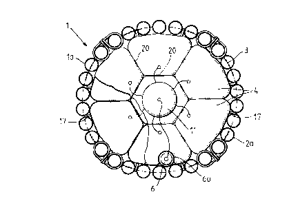
Figure 1 is an end elevatlon of a infl.atable fascine
Figure 2 is a longitudinal cross section through an
inflatable fascLne

Pigure 3 is a schematlc vLew showing the means ~or supplying
gas to the core members
Figure 4 Ls a schematic perspective view of a vehicle with
six inflatable fascines mounted for sequential
deployment.
The inflatable fascine 1 of the invention i9 shown in
Figures 1 and 2. The sleeve 2a formLng the outer surface of the
fascine comprises longitudinal sleeve members la which are made
from 4.5m lengths of 220mm outside diameter, 10mm thick, high
density polyethylene pipe. The sleeve members la are held in a
continuous neclclace formation by four chains 3 of 7mm steel alloy
chain. Two reinforcement liners 2 are coaxially located within
each sleeve member la. The liners 2 consist of 1.5m lengths of
196mm outside diameter, 6mm thick high density polyethylene pipe
and are located in the two outermost gaps between the chains 3.
Seven inflatable core members 4 made from 0.383 kg/m
fabric of woven aramid fibres such as KEVLAR (RTM) or T~ARON (RTM)
each containing an air tight inner tube are located inside the
sleeve 2a. The sleeve 2a also houses a compressed gas cylinder 6 in
a pipe 6a. The compressed gas cylinder 6 is connected to the core
members 4 by a ring main manifold 11 which is also shown in Figure
3. An on/off valve 12 is interposed between the gas cylinder 6 and
the manifold 11 in order to control the inflation of the fascine,
and one way valves 14 are interposed between the manifold and each
core member for allowing gas to flow into the core members only.
The one way valves 14 prevent the whole fascine from becoming
deflated if one core member 4 is punctured. An on/off valve 13 is
interposed between the manifold and each core member, so that if a
core member becomes punctured it can be isolated from the manifold
before the fascine is relnflated for subsequent deployment. Valves
13 are left open when the fascine is in an undamaged state. Between
each one way valve 14 and lcs assocLated core member 4 a branch pipe
containing an on/oEf valve 15 is provided to allow the fascine to be
deflated after use. Each core member 4 is provided with a pressure

y-i
relleE valve 16. The valves 13, 14 and 15 are located in an easily
accessible location.
The central core member is shorter than the surrounding
core members in order that a central section of the ring main
manifold can be accommodated without protruding from the end of the
fascine in either its inflated or deflated state. The central core
member may be shorter than the surrounding core members at both ends
as shown in figure 2 to accommodate a separate manifold with an
independent gas supply at each end of the fascine.
The lengths of the core members 4 are such thut when they
are inflated the ends of each core member 4 lie within the volume
enclosed by the sleeve 2a, and in order that they are not able to
pro~ect beyond the ends of the sleeve members la when the fascine is
deflated the ends of each core member 4 are connected by resilient
elasticated cords 5 which retract the ends of the core members as
the fascine is deflated. The core members 4 are connected to the
chains 3 by means of straps 17 which are bonded to the outside of
the core members.
The core members are connected to each other by hook and
loop joining fabric 20 in order to maintain the relative
juxtapositions of the core members when the fascine is deflated.
The joining fabric extends over the entire length of the core
members.
A launching means is shown in E'igure ~, which is capable of
~5 sequentially inflating and launching six fascines constructed
according to the invention.
The launching means comprises a platform 7 a ramp 8 and a
tracked launch vehicle ll adapted to carry six deflated fascines 1.
The platform 7 is mounted on the launch vehicle 11 and has the six
fascines 1 attached to its upper surface. In their deflated state
the fascines 1 lay back and are supported by a ramp 8 which slopes
upwardly from the rear end of platform 7. Each fascine l is
arranged with its gas cylinder 6 as near as possible to the point at
which the fascine is attached to the platform 7, and electrically or

3~j
cable actuated mechanlsms are provided whlch firstly allow
inflation of the fascine to take place and secondly release the
fascine thus allowing it to be launched. This release mechanism is
designed to ensure that a fascine can not be inflated or released
until all of the fascines in front of it have already been launched.
Figure 4 shows the first fascine 10 inflated and ready for
launching.

Representative Drawing
A single figure which represents the drawing illustrating the invention.
Administrative Status

2024-08-01:As part of the Next Generation Patents (NGP) transition, the Canadian Patents Database (CPD) now contains a more detailed Event History, which replicates the Event Log of our new back-office solution.

Please note that "Inactive:" events refers to events no longer in use in our new back-office solution.

For a clearer understanding of the status of the application/patent presented on this page, the site Disclaimer , as well as the definitions for Patent , Event History , Maintenance Fee  and Payment History  should be consulted.

Event History

Description Date
Inactive: IPC from MCD 2006-03-11
Time Limit for Reversal Expired 2005-10-24
Letter Sent 2004-10-25
Letter Sent 2004-03-30
Inactive: Correspondence - Transfer 2004-03-23
Inactive: Correspondence - Transfer 2004-03-15
Inactive: Correspondence - Transfer 2004-01-13
Inactive: Office letter 2003-11-17
Inactive: Correspondence - Transfer 2003-10-21
Letter Sent 2003-10-21
Grant by Issuance 1999-02-09
Pre-grant 1998-08-10
Inactive: Final fee received 1998-08-10
Inactive: Received pages at allowance 1998-07-03
Letter Sent 1998-02-16
Notice of Allowance is Issued 1998-02-16
Inactive: Application prosecuted on TS as of Log entry date 1998-02-09
Inactive: Status info is complete as of Log entry date 1998-02-09
Inactive: IPC assigned 1998-02-04
Inactive: IPC removed 1998-02-04
Inactive: First IPC assigned 1998-02-04
Inactive: Approved for allowance (AFA) 1998-01-02
All Requirements for Examination Determined Compliant 1996-10-18
Request for Examination Requirements Determined Compliant 1996-10-18
Application Published (Open to Public Inspection) 1990-04-24

Abandonment History

There is no abandonment history.

Maintenance Fee

The last payment was received on 

Note : If the full payment has not been received on or before the date indicated, a further fee may be required which may be one of the following

  • the reinstatement fee;
  • the late payment fee; or
  • additional fee to reverse deemed expiry.

Please refer to the CIPO Patent Fees web page to see all current fee amounts.

Fee History

Fee Type Anniversary Year Due Date Paid Date
MF (application, 8th anniv.) - standard 08 1997-10-23 1997-09-22
Final fee - standard 1998-08-10
MF (application, 9th anniv.) - standard 09 1998-10-23 1998-09-21
MF (patent, 10th anniv.) - standard 1999-10-25 1999-09-15
MF (patent, 11th anniv.) - standard 2000-10-23 2000-09-13
MF (patent, 12th anniv.) - standard 2001-10-23 2001-09-14
MF (patent, 13th anniv.) - standard 2002-10-23 2002-09-11
Registration of a document 2003-09-02
MF (patent, 14th anniv.) - standard 2003-10-23 2003-09-15
MF (application, 2nd anniv.) - standard 02 1991-10-23
Owners on Record

Note: Records showing the ownership history in alphabetical order.

Current Owners on Record
QINETIQ LIMITED
Past Owners on Record
DEREK IAN KNIGHT
Past Owners that do not appear in the "Owners on Record" listing will appear in other documentation within the application.
Documents

To view selected files, please enter reCAPTCHA code :


To view images, click a link in the Document Description column. To download the documents, select one or more checkboxes in the first column and then click the "Download Selected in PDF format (Zip Archive)" or the "Download Selected as Single PDF" button.

List of published and non-published patent-specific documents on the CPD .

If you have any difficulty accessing content, you can call the Client Service Centre at 1-866-997-1936 or send them an e-mail at CIPO Client Service Centre.


Document
Description 
Date
(yyyy-mm-dd) 
Number of pages   Size of Image (KB) 
Cover Page 1999-02-08 1 47
Abstract 1999-02-08 1 12
Claims 1999-02-08 3 84
Drawings 1999-02-08 2 50
Representative Drawing 1999-02-08 1 11
Descriptions 1999-02-08 6 181
Commissioner's Notice - Application Found Allowable 1998-02-16 1 165
Maintenance Fee Notice 2004-12-20 1 173
Correspondence 2003-11-17 1 8
Correspondence 1998-02-16 1 101
Correspondence 1998-07-03 3 98
Correspondence 1998-08-10 1 45
Correspondence 2004-03-30 1 11
Fees 1996-09-24 1 59
Fees 1995-09-20 1 52
Fees 1994-09-20 1 54
Fees 1992-09-23 1 24
Fees 1993-09-21 1 29
Fees 1991-09-24 1 30
Courtesy - Office Letter 1996-11-29 1 46
Prosecution correspondence 1996-11-05 5 294
Prosecution correspondence 1990-05-29 1 40
Prosecution correspondence 1996-10-18 1 45