Language selection

Search

Patent 2001317 Summary

Third-party information liability

Some of the information on this Web page has been provided by external sources. The Government of Canada is not responsible for the accuracy, reliability or currency of the information supplied by external sources. Users wishing to rely upon this information should consult directly with the source of the information. Content provided by external sources is not subject to official languages, privacy and accessibility requirements.

Claims and Abstract availability

Any discrepancies in the text and image of the Claims and Abstract are due to differing posting times. Text of the Claims and Abstract are posted:

  • At the time the application is open to public inspection;
  • At the time of issue of the patent (grant).
(12) Patent: (11) CA 2001317
(54) English Title: SLIDER PULL TAB FOR SLIDE FASTENER
(54) French Title: LANGUETTE DE GLISSIERE POUR FERMOIR
Status: Expired
Bibliographic Data
(52) Canadian Patent Classification (CPC):
  • 24/47
(51) International Patent Classification (IPC):
  • A44B 19/00 (2006.01)
  • A44B 19/26 (2006.01)
(72) Inventors :
  • ISHII, SUSUMU (Japan)
(73) Owners :
  • YKK CORPORATION (Japan)
(71) Applicants :
(74) Agent: GOWLING LAFLEUR HENDERSON LLP
(74) Associate agent:
(45) Issued: 1998-12-01
(22) Filed Date: 1989-10-24
(41) Open to Public Inspection: 1990-05-15
Examination requested: 1996-01-17
Availability of licence: N/A
(25) Language of filing: English

Patent Cooperation Treaty (PCT): No

(30) Application Priority Data:
Application No. Country/Territory Date
63-148914 Japan 1988-11-15

Abstracts

English Abstract


A slider pull tab for slide fastener is disclosed,
which comprises a connector means, a decorative portion
integral therewith and exposed to view at least on one
surface of the connector means and a grip web formed from
soft-type rubber or plastics material. The connector means
has a through opening and/or a through aperture which are
filled by the material of the grip web during formation of
the latter thereby providing increased tensile strength
against pull stresses exerted upon pulling the slider pull
tab.


French Abstract

Cette invention concerne une tirette de curseur de fermeture à glissière, qui comprend un connecteur à partie décorative intégrée et visible sur au moins une de ses faces exposées et un anneau en caoutchouc ou plastique souple. Le connecteur comporte un trou traversant et/ou une fenêtre qui sont remplis par une partie de l'anneau en cours de moulage de celui-ci, ce qui accroît la résistance à la traction à la manoeuvre de la tirette pour faire glisser le curseur.

Claims

Note: Claims are shown in the official language in which they were submitted.


CLAIMS

1. A slider pull tab for slide fastener which comprises a connector
means, a decorative portion integral therewith and exposed to view at least on
one surface of said connector means, and a grip web formed from an elastic
soft-type resinous material, said connector means having a through opening or
aperture which is filled by the resinous material of said grip web, wherein saidthrough-opening or aperture is formed in and extends transversely clear
through said decorative portion, and extends clear through the thickness of
said connector means.

2. A slider pull tab according to claim 1 wherein said connector
means includes a first connector and a second connector which are pivotally
connected by a pin.

3. A slider pull tab according to claim 2 wherein said pin is formed
on said first connector and engaged in a bore formed in said second connector.

4. A slider pull tab according to claim 2 wherein said pin is formed
on said second connector and engaged in a bore formed in said first connector.

5. A slider pull tab according to claim 1, further including an
additional decorative portion integral with said connector means.

6. A slider pull tabs according to claim 1 wherein said aperture is
located in close proximity to said decorative portion.

Description

Note: Descriptions are shown in the official language in which they were submitted.


~ 3~


BACKGROUND OF THE INV~NTION
Field of the Invention
This invention relates to sliders for slide fasteners
and more particularly to a slider pull tab made up from the
combination of a rigid portion and a flexible portion.
Prior Art
There are known a variety of slide fastener sliders
having associated therewith different forms and designs of
pull tab which are tailored to meet with the particular
specifications set up by the garment manufacturers who
produce all sorts of garment articles ranging from clothing,
sports wears, sports equipment to bags, etc.
A growing demand has recently been voiced for more
aethetically attractive slider pull tabs which are formed
predominantly of an elastic, flexible material such as
synthetic rubber, synthetic leather or other synthetic
resinous materials.
A slider pull tab made of such elastic material is
e~amplified in for instance Japanese Laid-Open Utility Model
Publication No. 62-102407, which pull tab feels soft and can
be gripped flexibly and non-slipplingly. However, since the
body of this pull tab is formed uniformly and solely from an
artificial soft rubber or resin, its appearance lacks
ornamental appeal. The prior art pull tab (as shown in FIG.
10) is further vulnerable to a pull force because it is
connected to the slider body through a connector which is
merely embedded in part within the material of the pull


' ': ~ ,
. .

2~ 13~L~


tab.
SUMMARY OF THE INVENTION
With the foregoing drawbacks of the prior art ln view,
the present invention seeks to provide an improved slider
pull tab of a flexible structure which is both ornamentally
attractive and abundant in tensile strength.
According to the invention, there is provided a slider
pull tab for slide fastener which comprises a connector
means, a decorative portion integral therewith and exposed
to view at least on one surface of said connector means, and
a grip web formed from an elastic soft-type resinous
ma.erial, the connector means having a through opening or
aperture which is filled by the resinous material of the
grip web.
The invention will be further described with reference
to the drawings, in which like reference numerals refer to
like or corresponding parts.
BRIEF DESCRIPTION OF THE DRAWINGS
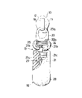
FIG. 1 is a partly sectional plan view of a slider
pull tab embodying the invention shown connected to a slider
body;
FIG~ 2 is a longitudinal cross-sectional view of the
pull tab in FIG. l;
FIG. 3 is a plan view of a connector assembly forming
part of the pull tab of FIG. l;
FIG. 4 is a longitudianl cross-sectional view of the
same;


-- 2 --


~- . :
,

2~, ~13~7


FIG. 5 is a diagrammatic perspective view of the pull
tab of FIG. l shown being manipulated;
FIG. 6 is a partly sectional plan vie~ of a modified
form of pull tab according to the invention;
FIG. 7 is a partly sectional plan view of another
modified form of pull ta~;
FIG. 8 is a longitudinal cross-sectional view of the
same;
FIG. 9 is a partly sectional plan view of still
another modified form of pull tab; and
FIG. 10 is a perspective view of a prior art slider
pull tab.
DETAILED DESCRIPTION
Referring new to the drawings and FIG. 1 in
particular, there is shown a slider 10 including a pull tab
embodying the invention, the slider 10 reciprocally movable
to open and close a slide fastener (not shown) in a well
known manner. The slider 10 comprises a slider body 11
formed by an upper flange 12 and a lower flange 13 defining
therebetween a guide channel 14 for the passage of coupling
element rows of the slide fastener and connected together at
one end by a neck 15, and an arch-shaped trunnion 16 having
an aperture 17 for pivotally receiving a pull tab 18.
The pull tab 18 shown in FIGS. 1 - 4 inclusive has a
connector means 19 including a first connector 20 and a
second connector 21 pivotally connected thereto and a grip
web 23 extending over the second connector 21.


'::

~ 3~7

The first connector 20 has at one of its ends a ring-
like hook portion 20a pivotally received in the aperture 17
of the trunnion 16 and at the opposite end a first
decorative portion 20~ having an integral pivotal pin 24
projecting transversely of the pull tab 18 a~ each of its
opposite ends.
The second connector 21 of t.he connector assembly 15
better shown in FIG. 3 consists of a tongue-like portion
21a, the majority of which is adapted to be embedded in or
enveloped by a plastics materia~ forming the grip web 23,
and a pair of arcuately shaped arms 21b each having one end
formed integrally with the upper end portion of the
tongue-like portion 21a and at the other end a transverse
bore 25 pivotally engaged with the respective pin 24 so that
the second connector 21 can rotate relative to the first
connector 20.
The second connector 21 further includes a second
decorative portion 21c projecting from and above opposite
surfaces of the tongue-like portion 21b as better shown
cross-sectionally in FIGS. 2 and 4. There is a through
opening 2~ formed in and extending transversely clear
through the second decorative portion 21c. A plurality of
elongate apertures 27 are also provided extending clear
through the thickness of the tongue-like portion 21b, one of
which borders with the second decorative portion 21c.
The grip web 23 is formed by injection-molding of a
suitable elastic, soft synthetic resin such as synthetic


, - ' ~
- , ~

2~ 3~

rubber, soft-type polyvinyl chrolide, polyurethane and the
like. During this injection-molding, the resinous material
flows into and fills up the opening 26 as well as the
apertures 27, resulting in the for~nation oE two directional
connecting bridges 26' and 27' oriented in the direction of
width and thickness respectively of the pull tab 18. The
connecting bridges 26' and 27' serve to prevent the grip web
23 from separating from the second connector 21 and also
provide increased tensile strength against pulling force
exerted when manipulating the slider 10 to open or close
the slide fastener by means of the pull tab 18.
soth first and second connectors 20 and 21 are formed
from a metallic material but may be likewise formed from
mechanically strong plastics material.
The decorative portions 20b and 21c of the first and
second connectors 20 and 21 respectively may present any
ornamentally attractive designs on their exposed surfaces or
may be attached with trademarks or planted with jewelries to
provide aesthetic appeal for such slide fastener parts as
sliders which have thus far been regarded more functionally
than ornamentally.
Various modifications of the pull tab structure
embodying the invention made be made as exemplified in FIGS.
6 through 9 inclusive.
The pull tab 18 illustrated in FIG. 6 features
combining the first and second connectors 20, 21 into a one-
piece structure devoid of the coupling means of pin 24 and


'' ~
. .
. . . - - ' ~ ; . . - ,

: ' ' ~ ,


bore 25. The decorative portion 21c of the second connector
21 carries an oval design exposed to view. The aperture 27
is arcuately shaped to extend along and in registry with
the lower portion of the decorative portion 21c.
The pull tab 18 shown in FIGS. 7 and 8 differs from the
embodiment shown in FIG. 1-4 in that the pins 24 are formed
integral with the second connector 21 and engaged in the
bores 25 formed in the first connector 20 to allow pivotal
movement of the latter, and in that the decorative portion
21c carries a vertically oriented oval design exposed to
view only on one surface of the grip web 23 and in that a
pair of arcuate apertures 27 are located respectively in
close proximity with the upper and lower peripheral portions
of the oval design.
FIG. 9 shows a one-piece structure of f irst and second
connectors 20, 21 which is similar to that of FIG. 6 but
which is characteri~ed by extension of the grip web 23 up
to the stem portion of the first connector 20.
Obviously, various modifications and variations of the
present invention are possible in the light of the above
teaching. It is therefore to be understood that within the
scope of the appended claims the invention may b~ practiced
otherwise than as specifically described.


-- 6 --

Representative Drawing
A single figure which represents the drawing illustrating the invention.
Administrative Status

For a clearer understanding of the status of the application/patent presented on this page, the site Disclaimer , as well as the definitions for Patent , Administrative Status , Maintenance Fee  and Payment History  should be consulted.

Administrative Status

Title Date
Forecasted Issue Date 1998-12-01
(22) Filed 1989-10-24
(41) Open to Public Inspection 1990-05-15
Examination Requested 1996-01-17
(45) Issued 1998-12-01
Expired 2009-10-24

Abandonment History

There is no abandonment history.

Payment History

Fee Type Anniversary Year Due Date Amount Paid Paid Date
Application Fee $0.00 1989-10-24
Registration of a document - section 124 $0.00 1990-03-05
Maintenance Fee - Application - New Act 2 1991-10-24 $100.00 1991-08-22
Maintenance Fee - Application - New Act 3 1992-10-26 $100.00 1992-07-31
Maintenance Fee - Application - New Act 4 1993-10-25 $100.00 1993-08-27
Maintenance Fee - Application - New Act 5 1994-10-24 $150.00 1994-08-24
Maintenance Fee - Application - New Act 6 1995-10-24 $150.00 1995-09-06
Maintenance Fee - Application - New Act 7 1996-10-24 $150.00 1996-09-16
Maintenance Fee - Application - New Act 8 1997-10-24 $150.00 1997-09-11
Maintenance Fee - Application - New Act 9 1998-10-26 $150.00 1998-07-14
Final Fee $300.00 1998-07-22
Maintenance Fee - Patent - New Act 10 1999-10-25 $200.00 1999-07-09
Maintenance Fee - Patent - New Act 11 2000-10-24 $200.00 2000-07-14
Maintenance Fee - Patent - New Act 12 2001-10-24 $200.00 2001-09-18
Registration of a document - section 124 $0.00 2001-11-28
Maintenance Fee - Patent - New Act 13 2002-10-24 $200.00 2002-09-19
Maintenance Fee - Patent - New Act 14 2003-10-24 $200.00 2003-09-17
Maintenance Fee - Patent - New Act 15 2004-10-25 $450.00 2004-09-09
Maintenance Fee - Patent - New Act 16 2005-10-24 $450.00 2005-09-08
Maintenance Fee - Patent - New Act 17 2006-10-24 $450.00 2006-09-08
Maintenance Fee - Patent - New Act 18 2007-10-24 $450.00 2007-09-07
Maintenance Fee - Patent - New Act 19 2008-10-24 $450.00 2008-09-15
Owners on Record

Note: Records showing the ownership history in alphabetical order.

Current Owners on Record
YKK CORPORATION
Past Owners on Record
ISHII, SUSUMU
YOSHIDA KOGYO K.K.
Past Owners that do not appear in the "Owners on Record" listing will appear in other documentation within the application.
Documents

To view selected files, please enter reCAPTCHA code :


To view images, click a link in the Document Description column. To download the documents, select one or more checkboxes in the first column and then click the "Download Selected in PDF format (Zip Archive)" or the "Download Selected as Single PDF" button.

List of published and non-published patent-specific documents on the CPD .

If you have any difficulty accessing content, you can call the Client Service Centre at 1-866-997-1936 or send them an e-mail at CIPO Client Service Centre.


Document
Description 
Date
(yyyy-mm-dd) 
Number of pages   Size of Image (KB) 
Claims 1998-02-18 1 30
Representative Drawing 1998-11-06 1 9
Abstract 1994-02-05 1 15
Cover Page 1994-02-05 1 13
Claims 1994-02-05 1 34
Drawings 1994-02-05 3 88
Description 1994-02-05 6 200
Cover Page 1998-11-06 1 39
Correspondence 1998-07-22 1 36
Prosecution Correspondence 1996-01-17 1 34
Prosecution Correspondence 1997-09-10 1 28
Examiner Requisition 1997-03-18 2 67
Office Letter 1996-02-02 1 48
Fees 1996-09-16 1 95
Fees 1995-09-06 1 97
Fees 1994-08-24 1 112
Fees 1993-08-27 1 66
Fees 1992-07-31 1 60
Fees 1991-08-22 1 46