Note: Descriptions are shown in the official language in which they were submitted.
1 - 200~6~34
_etbotJ Or and ~pl~r.atus ~ol Sup~orting th~ Ituman Body
The present invention relates in general to a
method of and an apparatus for supporting the human body
and in particular to a massags spparatus which i9
adapted to serve as a mattress, pad or the like for
producing massaging effect.
Conventionally, it has been believed that a pad or
mattress having a soft feeling assures a sound sleep.
The conventionsl mattress is made of extremely soft
material, such as urethane foam rubber. However, such
mattress is so soft that the spinal cord of a user tends
to bend downwardly durlng sleeping. Consequently, the
weight of the user cannot be uniformly supported by the
mattress. The user often feel~ pain in his shoulder, .
waist or spinal cord. ûn the other hand, some people
believe that a mattress made of hard material as~ures a
sound sleep. ~lowever, in practice, this type of
nlattre~s is not suital)lt ror any person except
youngster3, 9ince .i t cause3 the upward clJrving of the
spine and the stretching Or muscles.
Accordingly, the ideal condition of a pad or
;, . : ~ , .,. - --. .
:,: . , ;: : . , ., . : - . :
. ~ ;
. . - , . . : . .
:: . : -. - .
_ 2 - 20~16~4
mattress is ~oft to the touch but firm enough to
urli rOIunly di~ributc lhe U5el' ' 3 weight.
However previously proposed mattresses meeting
these criteria are relatively bulky and heavy. In
addition, they canoot be rolled up for easy storage and
transportation and do not promote the respiration of
skin of the user's body and to prevent undesirable rises
in body temperature.
~ n accordance with one aspect of the present
invention, there is provided human body support
apparatus comprising means defining an array of pressure
points for the application of pressure to parts of the
human body, means for connecting said first mentioned
means to form a layer, and cover means for covering ~ald
layer.
The beads are preferably made of a relatively hard
material, such a-i w~od, plastic or rubber. The beads
are preferably spherical, semispherical, oval, elongated
or irregular in shape or a combination thereof. The
beads are preferably disposed in orthogonal, diagonal or
irregular array.
,
. . .
1684
According to a first embodiment of the invention,
eacll of the beads has a through hole whereby the beads
are adapted to be linked up together by string or line
means. The strings are made of a flexible and high
tensile material such as thread, nylon or steel wire.
According to a second embodiment of the invention,
the beads are ~ecured to a sheet member fabrlcsted of
cloth, of nylon or other suitable materials.
The cover serves to enclose the layer of beads and
produce a clean and comfort outlook for the n)attress or
pad. The cover is preferbly made o~ cloth or thin foam
rubber.
/orlo~er
The mattless or pad of the present invention may
further be provided with magnetic clevices such as
magnets. The magnets are positioned between and among;
the beads and are disposed at the regions of the
mattress which come into cloRe contact with the body of
the user.
The magnetic force generated from the magnets has
a healing effect on users suffering from fatigue. It
releases the user from pain in the spinal cord and waist
and from stiffness in the shoulders.
::: - - :. . . ...
. . .~
.. .: . . . .
, . -.... , ., . . :.
: ' : : .. '' :. . ' ., - ' ,, '., . ' '
.~ . . - . .
- " - 2~ 8~
A unitary layer of the beads uniformly supports
body of the user and produces massaging effects at
v~3rious points of the body of the user.
The mattress or pad is characterized in that a lot
of space i9 provided between the beadq rendering the
mattress or pad to have excellent ventilation. It
allows the sweat which is formed to be effectively
ventilated away so that the body is held at a suitable
temperature.
In accordance with a further aspect of the
invention there is provided a method for supporting a
human body comprisirlg the step of resting a part of the
human body on or against a layer which defines an array
of pressure points for the application of pressure to
said part of the body.
,
Many other advantanges and features of the present
invention will become apparent to those skilled in the
art upon making reference to the detailed description
and the accompanying drawings in which preferred
structural embodiments incorporating the principles of
the present invention are shown only by way of
illustration.
: ~ - - - . - . ~ . .
: : , . . .
"
': ' ''
. : . , . - :: . :
-- 5
2~ 1684
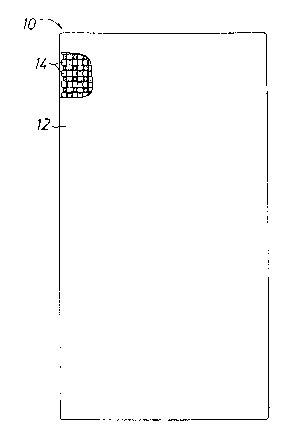
Figure 1 is a plan vie~l of a mattress or pad --
. ,,, - , , . .. , ., . - . . . ... .
:. . : :
~, . ; , .:., ~-:. ' ' . -'. ' `
~, . . . : . .-. - :.
.: ~ ~ . -
.. :: - , :, . : . .: ~ .. : - ;
:, . : . - .. : : . .
.:,., : . . :: : :
: -.. . - .
: ; :
... .. .
Z~ i84
accordillg to the present invention with a portion of the
cover being cuta~ay showing the inner structure thereo.
Figure 2 is an enlarged fragmentary plan view
o a layer of barrel-shaped beads.
5Figure 3a is a barrel-shaped bead according to
tlle embodilnent in Figure 2.
Figure 3b is a second embodiment oE the bead
in a spherical configuration.
Figure 3c is a third embodiment of the bead
in an oval or generally elongated configuration.
Figure 3d is a fourth embodiment of the bead
in an irregular con~iguration.
Figure 4 is a sectional view of the layer of
beads taken generally along line I-I of Figure 2.
lSFigure 5 is an enlarged fragmentary plan view
oE another embodiment o~ the layer Oe beads.
Figure 6 is a semispherical bead without a
through hole in accordance with the embodiment of Fig~ré
5.
20Figure 7 is a sectional view of the layer of
beads taken generally along line II-II of Figure 5.
Figure 8 is an illustrative diagram showing
the pressure points located on the back of the human
body.
25Figure 9 is an illustrative diagram showing
some commonly used acupuncture points located at the
.:, ,. . :
: . : : '.,
: ,
X0~1~84
front o~ the humall body.
Figure 10 is an illustrative diagram showing
some commonly used acupuncture points located on the
back of the human body.
SFigure 11 is an illustrative diagram showing
some commonly used acupuncture points located on the
side Oe the human body.
Figure 12 is an explanatory diagram showing a
human subject uqing a massage apparatUQ of the present
invention which serves as a mattress.
Figure 13 is an explanatory diagram showing a
human subject using a massage apparatuQ of the present
invention which serves as a seating.
Referring now to the drawing, in which like
reference numerals represent like part~ throughout the
views, Figure 1 shows a plan view o a pad or mattress
designated generally by reference numeral 10. The pad
or mattress 10 of regular size consiQts o a cover 12
covering, according to the preferred embodiment, a
single layer o beads 14. The beads 14, form$ng the
mattress body, are linked up together by threads or
strings 16 to prevent displacement thereof.
Figure 2 is an enlarged plan view of the
mattress 10 depicting detail construction of the layer
of beads 14. Each of the beads 14 is, according to the
present embodiment, generally barrel-shaped having a
.. . - - :~: '
-. , , - , ` ~ : .
: . :
200~6~4
lbrou~Jb bole 18.
lhe beads l~l are arranged diagonally with respect
to one anotller. Tlle through holes 18 of a row of beads
14 are longitudinally disposed whilst the through holes
18 of thc adjacenl row of beads 14 are latitudinally
disposed as illustratrd in Figule 2.
~ lthough llle bead, 14 h<lve beell described as being
arranged in diagonal relationsllip, it is understood that
they may be arranged in ortllogonal, irregular, or other
relationships without departing from the scope of the
present invention.
Figure 3a is a perspective view of the
barrel-shaped bead 14 shown in Figure 2. The bead 14
has a longitudinally extending through hole 18.
The beads 14 may be of other configuration as . r
shown in Figures 3b, 3c and 3d. The pad or mattress 10
may consist of spherical beads 14', elongated or oval
beads 14 " , beads 14 " ', of irregular shape, or a
combination thereof. The size of beads 14, 14', 14'',
14''' may vary and, preferably, in the region of
5mm-4ûrnm in dimension.
Figure 4 shows a sectional view of the rnattress 10
. ~ .
.
,
." ' ' " : ~ ' .
.: . .
- ~a - 2001684
in accordance witl1 tl1e embodiment sho~n in Figure 2. It
can be seen that the beads 14 are linl<ed up together
form.ing a unitaly layer of mattles~. A bedding layer 15
of foam rubber or other resilient material i9 located
be~t1tath the layeL Or l)cocls 1~l in orclcr tu produce a
cushioning effect. This foarn rubber bedding preferably
has a thickness of 1.2 cm to 5.0 cm.
The mattress cover 12, preferably fabricated-
~ .
... . : ,
,:: ,,, . ., . -
.. . . . .
20C~1684
g
froln cloth, or thin foalll rubber, or other desirable
materials, serves to cover tlle layer of beads 14 and
give a clean and comfort outlook for the mattress 10.
The strings 16 are made of a flexible and high
tensile material, sucll as thread, nylon, or steel wire
so as to hold the beads 14 in a fixed position with
respect to one another. The beads 14 are made of a
relatively hard material such as wood, plastic, or
rubber. The mattress 10 is therefore given good
characteristics by means of relativeiy inexpen~ive
materials.
Figure 5 shows an enlarged plan view of a
second embodiemnt of the pad or mattress of the present
invention which is generally represented by reference
numeral 10'. According to this preferrod embodiment,
beads 24 are secured to a sheet member 26 to form the
mattress body. According to the preferred embodiment,
each of the beads 24 is semispherical in shape and has
no through hole provided thereon, as shown in Figure 6.
A substantially flat bottom surface 22 is provided on
each of the beads 24 and is adapted to be seated on the
upper surface o~ the sheet member 26.
rhe beads 24 are preferably adhered to the
sheet member 26 by adhesive means such as glue. The
beads 24 may also be secured to the sheet member 26 by
other conventional means. According to the embodiment
. . . . ~ - .: .
, . . . , .. . .. ~ ~,
20~31684
- 10 -
shown in Figure 5, the beads are arranged in orthogonal
relationship with one another. This permits automation
of the manufacturing process.
The beads 24 are preferably made o~ wood,
plastic, or rubber. The sheet member, serving as a base
of the mattress body, is made of a ~lexible material
such as a piece of cloth of strong fiber, or nylon, or
other suitable materials.
Alternatively, the beads 24 may also be
provided integrally with hole or holes to allow the
beads to be threaded to the sheet member 26.
A cover 28 is used to cover the mattress body
to provide a com~ort and clean outlook to the mattress
10' .
Figure 7 is a sectional view of the mattress
10' in accordance with the embodiment ~hown in ~igure 5.
It can be seen that the beads 24 are disposed in a
spaced relationship with one another. This renders the
mattress 10' to be in a good ventilating condition and
allows the mattress 10' to be rolled up for storage.
This beads-and-sheet construction is more
flexible in the sense that the beads 24 can be attached
to the sheet member 26 in any pattern. Furthermore,
mass production of the mattress 10' is made feasible.
The mattress 10 or 10' of the present
invention may further be provided with magnetic devices
: , , . : ': ' . - - - ~.. . ..
,;
.. ; -. ~. . ,, : .. .
: ~ .. .
'' ' . ~ . . .
.. : . . . .
:
. . ,~
200168~ -
such as magnets o an appropriate magnetic flux
density. As illustrated in Figure~ 5 and 7, magnets 30
are in the shape o a disk and are generally positioned
between and among the beads 24. These magnets 30 are
S provided and secured at the regions of the mattress lO'
which come into close contact with the body of the user.
Magnets may also be mounted on the mattress lO by string
means or other suitable means. These magnets act
further to manipulate the body of the user for remedial
purposes.
The magnetic force generated from the magnets
has a healing efEect on users sufering from fatigue.
It releases the user erom pain in the spinal cord, waist
and other parts o~ the body. It also eases stie
shoulders of the user. The magnetic force also adjusts
the functions of the human organs o the user.
When a user lies on the mattress lO or 10'
during treatment, the layer of beads 14 or 24, defining
an array of pressure points, uniformly support the body
of the user and apply pressure at a number of pointq. on
the back of the body. This gives rise to a similar
effect of a treatment of finger massage or massage by
means of an electrical massage apparatus. The points on
the back of the body known to respond to pressure are
indicated by reference numeral 20 shown in Figure 8.
l`hese points are held to correspond with
, . .. . : . .~ . , -~
. ,: . . . . . :
.~ : . , . ~.
.
- 12 - 2~0~684
specific orgar)s of lhe l1umal- body. When they sre
slimulaLed, the corresponcling organs are being treated
and respond to the stimulation.
It i8 believed that vi~al energy ~low constantly
throughout the hulnan body. According to the Chinese
conceptiol1 this vital energy is made up of a balance
mixture of the Yin and Yang. This is the continuous
flow of this vital energy both over the entire surface
of the body and slong the special lines or channels
which correspond with the major organs within the human
body. Some of these lines or channels, which are called
meridians in the West, correspond with the heart, liver,
spleen, lungs, kidneys, and other with the large and
small intestines, stomach, bile ducts and the bladder.
The apparatus of the present invention i8 at least
as effective as taking pills and medicine, for the
relief from a lot of diseases and pains occuring in :
various parts of the body, including lumbago, sciatica,
insomnia, constipation, hypertension, headache, knee
pain, back pain, and stiff necl< and shoulders. It helps
to promote blood and vital energy circulation and speeds
up metabolism of the body.
,
Some oF the points used for treatment Or the human
body are indicated in Fiyures ~, 10 and 11.
;.. . ~ ~ . . . - ' :
20~l6a~
- 13 -
These points and their names and corresponding
indications are listed as follows:
Point Name Indication
B10 Tienchu Stiff neck, Neurasthenia,
Hysteria, Headache.
B23 Shenshu Lumbago, Impotence.
B25 Tacllangshu Constipation, Lumbago.
B37 Pohu Sciatica, Hemiplegia.
B40 Yihsi Sciatica.
B47 Chihshih Lumbago, Impotence, Dysuria.
B50 Chengfu Neuralgia in the limbs.
B51 Yinmen Sciatica, Hemiplegia.
B53 W~iyang Ankle dullne~s and pain.
B54 Weichung Sciatica, Hemiplegia.
B57 Chengshan Gastrocnemius muscle cramp,
Leg pain.
B60 Kunlun Sciatica, Hemiplegia.
CV4 Kuanyuan Dysmenorrhoea, Impotence,
Diarrhoea.
CV12 Chungwan Gastroptosis, Nausea, Stomach
diseases.
CV17 Shanchung Mental strain.
GB21 Chienchin Shoulder pain.
GB30 Huantiao Lumbago, Sciatica
G~31 ~engshih Paralysis o~ the legs.
GB34 Yanglingchuan Cholecystitis, Hemiplegia,
, . - -., -
... :. : .: -
. ~ . :: .
~. : :.
.
: ~: .,.,. . . . ~ . ... . :
2~)0~684
- 14 -
Liver and gall-~ladder
diseases.
GB37 Kuangming Blurred vision.
GB39 Hsuanchung Ankle joint pain.
GVl Changchiang Hemorrhoids.
GV4 Mingmen Lumbago, Impotence.
GV12 Shenchu Mental strain, Insomnia.
GV14 Tachui Back pain, Stiff neck.
GV16 Fengfu Headache, Stiff neck,
Apoplexy.
K26 Yuchung Bronchitis.
LIll Chuchih Hypertension, Paralysis,
Elbow pain.
LI14 Pinao Arm pain, Hemiplegia.
LI15 Chienyu Frozen shoulder, Hemiplegia.
LIV7 Hsikuan Arthritis of the knee.
LIV8 Chuchuan Arthritis of the knee.
LIV14 Chimen Diabetes, Mental strain.
S25 Tienshu Acute or chronlc gastro-
enteritis, Distenslon of the
abdomen.
S34 Liangchiu Knee weakness and pain,
Gastric pain.
S36 Tsusanli Indigestion, Diabetes,
Vomiting.
SI9 Chienchen Shoulder pain, Tinnitus.
.
.~ . ... .
20~7~684
-- 15 --
SI15 Chienchungshu Insomnia, LumbagQ.
SP10 Hsuehhai Thigh pain, Menorrhagia.
The mattress 10 or 10' is relatively thin and
light in weight as compared with conventional bulky
spring mattress. The beads-and-string construction and
the beads-and-sheet construction render the mattress 10
or 10' to be very flexible and, as such, can be rolled
up for easy storage and transportation.
Due to the fact that a lot of space is
provided between the beads 14 or 24, the mattress 10
and 10' of the present invention have a good ventilating
property. Thus, inhibition of respiration of the skin of
the body and undesirable rise in body temperature can be
minimized and a sound sleep can be guaranteed.
Although the layer of beads has been described
hereinbefore as being a mattress, it is contemplated
that the layer of beads may be incorporated for other
purposes. For example, the layer of beads may be
incorporated to a seating or a floor mat.
Figures 12 and 13 are explanatory dlagrams
showing the layer of beads being used as a mattress and
a seating respectively.
While the present invention has been shown and
described with particular reference to a preferred
embodiment thereof, it should be noted that various
other changes and modifications may be made without
- . :.. ., . ~ -,, ~;
. : : : :. . ::
-, ~ ,. :
: - .- : - - - .
. ~ : . . : ....................... .
2(~01684
-- 16 --
departing from the scope of the present invention.
. .
~ . ~ '' ,
'', ' : - : :
~ . . . .