Note: Descriptions are shown in the official language in which they were submitted.
20017Z;~
METHOD AND ARRANGEMENT FOR AN ENFORCED HEAT TRANSMISSION
BETWEEN BODIES AND GASES
The present invention relates to a method and an apparatus for enforced heat
transmission between a body, solid or liquid, and an ambient gas. In particular, the
invention relates to heat transmission from relatively small solid bodies, which occur
in large amounts, and where it is desirable for a fluidization of the forward flowing
~5 bodies to be materialized in order thus to improve both the heat transmission and the
;:motion of the bodies. The enforced heat transmission is achieved in that the ambient
gas is set in oscillatory motion which is generated by a standing sound wave of low
frequency and in that the forward flowing bodies are placed in that part of the sound
wave where the oscillatory motion is greatest.
A fundamental problem in heat transmission, for example from a warm body to an air
flow enveloping the body, is that the transferred thermal effect per surface unit from
the body to the gas flow will be slight at low gas flow rates. In order to transfer large
thermal effects, high gas flow rates are required, which implies that a large air flow will
15 be necessary. At the same time, however, the temperature rise in the air will be slight.
The large flow entails that cooling will be expensive and, in consequence of the slight
temperature rise, the energy in the heated air can seldom be utilized.
It is previously known from V. B. Repin, "Heat exchange of a cylinder with
20 low-frequency oscillations", Zhurnal Prikladnoi Mekhaniki i Tekhnicheskoi, No. 5, pp.
67-72, September-October 1981, that heat transmission may be improved by
generating a sonic field in the gas. It is also previously known that it is advantageous
if such a sonic field is of low frequency.
25 It will be obvious from the two parameters sound pressure and particle velocity in a
sonic field that it is th~ particle velocity which provides the enforced heat transmission.
It is also obvious that the heat transmission increases with increasing particlevelocities. The reason why the prior-art method of employing low-frequency sound for
200~7~2
heating or cooling of bodies has not hitherto enjoyed any practical importance is that
there have not been any usable methods or apparatus for generating sound with a
sufficiently high particle velocity throughout the entire surface of the body intended to
be cooled, or alternatively, heated.
The object of the present invention is to solve the above-mentioned problem and to
realize a method and an apparatus for achieving an enforced heat transmission bytransferring high thermal effect per surface unit from a body to ambient gas, especially
for applications in which the body consists of a quantity of small solid bodies, for
10 example in the form of granules or as pellets or drops. Instead of increasing the heat
transmission by aspirating the gas over the surface of the body at high speed, the
enforced heat transmission is achieved by imparting to the ambient gas a low
frequency oscillation. For the purposes of clarifying the present invention, three
different embodiments thereof with regard to cooling will be described.
The nature of the present invention and its aspects wili be more readily understood
from the following brief description of the accompanying drawings, and discussion
relating thereto:
Fig. 1 shows a solid body in a standard air flow;
Fig. 2 shows a solid body in an air flow which has been exposed to an
infrasound field;
Fig. 3 shows an embodiment of an apparatus according to the invention;
Fig. 4 shows another embodiment of an apparatus according to the invention;
Fig. 5 shows a third embodiment of the invention which can be used in an
installation for cooling of plastic granules;
Fig. 6 shows a fourth embodiment of an apparatus according to the invention
which is particularly suitable for freezing of vegetables;
Fig. 7 shows an apparatus for cooling of foundry sand according to the
invention.
As was mentioned above, an enforced heat transmission may be achieved between
the surface of a body and an ambient gas if the gas is influenced so as to reciprocate
. - .
Z00172~
with the aid of a standing sound wave generated in the gas. Fig. 1 shows a solid body
at a temperature To which is exposed to an air flow. A particle in the air flow is marked
as a dot and the position of the air particle at various points in time is marked by t1-t7.
The temperature of the air flow is T1 before it has passed the body, and T~ after the
5 body has been passed. Fig. 2 shows the same solid body when it has been exposed
to the same air flow, but under the influence of infrasound. The position of the air
particle at different points in time is also marked by t1-t7 here. As will be apparent,
each air particle which passes the solid body, because of the pulsating air current
generated by the low frequency sound, will pass not just once but a plurality of times.
10 If the body is of a higher temperature than the air flow, the air particle will absorb more
and more heat each time it passes the solid body, and the temperature of the body
will be correspondingly reduced. Enforced heat transmission will thus be obtained.
In certain parts of the standing sound wave, the velocity of the oscillating motion of the
15 gas, the so-called particle velocity, is great, while the pressure variations, the
so-called sound pressure, are slight. In other parts, the pressure variations are great
while the velocity of the oscillating motion is low. At a certain point, both the particle
velocity and the sound pressure will thus vary with time and, under ideal conditions,
will describe a sinusoidal oscillatory motion. The highest value of the particle velocity
20 and the sound pressure, respectively, is indicated by the amplitude of each respective
oscillatory motion. As a ruie, the amplitude of the partice velocity assumes a maximum
value, i.e. has a so-called particle velocity anti-node, at the same time as theamplitude of the sound pressure assumes a minimum value, i.e. has a so-called
sound pressure node.
It is desirable, in accordance with the foregoing, that the particle velocity assumes as
high a value as possible in order that maximum enforced heat transmission be
obtained. In a standing sound wave, there may be several positions where the
particle velocity amplitude assumes its maximum level. In a standing sound wave
30 whose length corresponds to a quarter or a half wavelength, or alternatively a part of
a quarter or a half wavelength, the amplitude of the particle velocity has a maximum
only at one point. In order to obtain as high an enforced heat transmission as
" ~ ~
zo~q~
possible, the surface from whence the heat transmission is to take place should
therefore be sited at a position as close to the particle velocity anti-node as possible.
In the method according to the present invention, an enforced heat transmission
5 between a body, solid or liquid, and a gas, as shown in Fig. 2, is realized in that a
standing, low-frequency sound wave is generated in a closed, or in any case
acoustically virtually closed, sound resonator. The term low-frequency sound is here
taken to mean sound at a frequency of 50 Hz or lower. The reason why frequenciesabove 50 Hz are less interesting is that such a closed half-wave resonator has such
10 small dimensions at high frequencies that the whole apparatus will be uninteresting
from the point of view of capacity. Since possible disruptive sound fades at lower
frequencies, a frequency of 30 Hz or lower should preferably be used. At this
frequency, disturbances may be considered as very slight. The sound resonator ispreferably of a length corresponding to a half wavelength of the generated
15 low-frequency sound, but other designs of the sound resonator are also possible. The
sound wave is obtained in that air pulses are generated by a so-called exigator
located at a sound pressure anti-node in the resonator. The term exigator is here
employed to indicate that part of a generator for low-frequency sound which
generates a particle velocity in one point in a resonator where a high sound pressure
20 prevails, see for example Swedish patent No. 446 157 and Swedish patent
applications Nos. 8306653-0, 8701461 -9 and 8802452-6. Somehwere in the
resonator a particle velocity anti-node will occur and here the body is supplied which
is to be exposed to an enforced heat transmission. If the body in question consists of a
substance which occurs in the form of granules, pellets or similar, the particle velocity
25 of the sound can also act fluidizingly on the substance in question.
In the case when the body in question, which constitutes an obstacle to the sound,
becomes all too large, this is revealed in that the sharpness of the resonance of the
resonator becomes poorer, which means that the ratio between the amplitude of the
30 particle velocity in the anti-node and node respectively decreases. In a condition with
large losses there is therefore no reason to generate the standing sound wave with
the aid of a long rffsonance tube. By placing the exigator closer to the particle velocity
anti-node the resonance tube can be shortened.
,, ;,
. .
., . ~.
~,
2001722
In the practical designing of the sound resonator there are several possibilities.
Examples of different embodiments are illustrated in Figs. 3-5, the principles of which
are briefly described here. In all cases an acoustically closed system is aspired to.
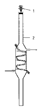
Fig. 3 shows a generator for low-frequency sound with an exigator 1 and a resonator
5 2 with a length corresponding to a half of a wavelength of the generated
low-frequency sound. A particle velocity anti-node occurs in an area close to the
middle of the resonator and consequently the substance which is to be exposed to an
enforced heat transmission is supplied just above the middle of the resonator and
drained just below the middle thereof. Fig. 4 shows a resonator which functions in the
10 same manner as the resonator in Fig. 3 with the difference tha~ the lower half of the
resonator has been replaced by a resonator of Helmholtz type. Here there is thus a
tube resonator 3 with a length corresponding to a quarter of a wavelength combined
with a Helmholtz resonator 4 which is so dimensioned that it is tuned for the same
resonance frequency as the tube resonator, implying that the tube resonator and the
15 Helmholtz resonator in this case jointly form one resonator. In Fig. 5 and 6 the
Helmholtz resonator in Fig. 4 has been given a funnel shape so that the substance
which is to be exposed to enforced heat transmission is collected up by the
Helmholtz resonator 10, 20 and, through an opening in its bottom, is passed on. Fig. 7
shows another variant in which two resonators 30, 31 each with a length
20 corresponding to a quarter of a wavelength, have been placed side by side so that
their open ends are in communication with each other. Two exigators 32, 33 generate
a standing sound wave of the same frequency in each resonator. By permitting these
exigators to operate in counterphase, there is generated one single common standing
sound wave. In principle, this joint resonator functions in the same manner as a25 half-wave resonator.
In a case with a sound resonator of irregular shape the appearance of the amplitude
of the particle velocity is influenced so that the original sinus wave shape becomes
difficult to recognize. The volume velocity of the sound, however, is not influenced in
30 the same way and instead it retains its sinus wave shape, which in periodicity
coincides with the amplitude of the particle velocity. In the case of a sound resonator
of irregular shape it may thus be more appropriate and easier to identify the area
where the largest heat transmission can be obtained as the area where the volume
.
. . ...
. : . -
~1722
velocity has an anti-node.
The invention will now be described in greater detail with reference to three
embodiments which concern cooling.
Fig. 5 illustrates an apparatus for cooling of plastic granules. An infrasound generator
of the type described in Swedish patent application 8802452-6 can, for example, be
used. This comprises a tube resonator 11, which preferably has a length equivalent to
a quarter of a wavelength, at one end of which an exigator 12 is mounted. At its other
10 end it is fitted with a diffusor 13 which is directly mounted on a cooling tower 14
through the upper end of which hot plastic 15 in the form of granules is supplied via a
supply pipe 16. Together with the diffusor, the cooling tower and the Helmholtz
resonator 10, the tube resonator forms a resonator corresponding to a half-wave
resonator. The diffusor and the cooling tower are situated within an area in which a
15 volume velocity anti-node occurs. The hot plastic granules 15 fall by the force of
gravity down through the cooling tower 14. The tower is furnished with a number of
inclined obstacles 17 which momentaneously catch up the plastic granules so that the
transport time of the plastic granules through the area with a high volume velocity is
prolonged. The obstacles consist preferably of trays fitted with nets, but the obstacles
20 may also have other designs which permit air to pass through them while the plastic
granules are unable to pass through them, e.g. pipes, beams or similar. At the lower
end of the tower there is a Helmholtz resonator 10, which functions like a funnel and
catches up the plastic granules for further transport to a container. At the upper part of
the Helmholtz resonator, cooling air is supplied from a fan through a duct 18. This air
25 rises up through the cooling tower and is heated by the plastic granules. The heated
cooling air is discharged through a duct 19.
'`
Enforced heat transmission is obtained between the granules and the gas influenced
by low-frequency sound, in this case air. When the granules are caught up by the30 obstacles the air motion generated by the sound accomplishes a fluidization of the
granules.
Fig. 6 shows another embodiment which is particularly suitable for the freezing of
.. . . . . .
: ~ - ~ . -, ,: - . - . - - :
.. . ,. - .~ ,
- . : ,. ~. ,, . ,: , ~ ..
2001722
vegetables. The cooling air has been replaced by a closed system of pipes for a
cooling agent such as water, ammonia, freon. The pipes 21 are installed between the
inclined obstacles 17 and by allowing the piping system to constitute a part of a
heat-exchanger system the heat given off by the bodies, in this case the vegetables,
5 can also be utilized.
Fig. 7 shows an embodiment in which hot sand from a foundry is cooled. The
apparatus consists of two resonators 30, 31 both of which have a length
corresponding to a quarter of a wavelength. Located at the upper end of each
10 respective resonator is an exigator 32, 33 which in this case also can appropriately be
of the type described in Swedish patent application 8802452-6 or equivalent. These
two exigators 32, 33 are driven by a common motor 34 such that they operate in
counterphase with each other. By this means a single common standing wave is
generated in the two resonators, which are situated side by side so that their open
15 ends 35, 36 are in communication with each other through a joint space 37. In the
lower part of each respective resonator and in the proximity of the joint space 37, an
zone is obtained with a volume velocity anti-node which constitutes the actual cooling
zone. Installed in the cooling zone are obstacles in the form of pipes 38, 39 which are
conveyed to and fro several times within the cooling zone and thus form two pipe20 systems. A cooling agent such as water, ammonia, freon or similar, flows through
these pipes. The sand to be cooled is supplied to the apparatus from above through a
pipe 40 which has two branches 41, 42 emanating immediately above the two pipe
systems. The supplied sand passes slowly down through the pipe systems with the
aid of the force of gravity and is cooled during this passage. The outside of the pipe
25 systems then constitutes a convection surface so that a heat transmission takes place
first between the grains of sand and the air inside the resonators and thereafter
between the air and the convection surface. The heat absorbed by the coolant is
subsequently led off to be used, for example, for heating. When the sand has been
cooled and has passed the obstacles 38, 39 it is collected and removed through a30 duct 43 situated at the lower portion of the joint space 37.
In the embodiments of the present Invention described in the foregoing, the enforced
heat transmission has solely been illustrated in the form of cooling and freezing
- ~" -
. .
. .~: . - -
~ ~ .
. ,
-
,
200~722
processes, but the present invention may naturally also be used for other types of
processes in which an enforced heat transmission is desirable, for example heating,
drying, etc.
` , '~ ' ~
- ~ ... - . ,: . ,
.