Language selection

Search

Patent 2001783 Summary

Third-party information liability

Some of the information on this Web page has been provided by external sources. The Government of Canada is not responsible for the accuracy, reliability or currency of the information supplied by external sources. Users wishing to rely upon this information should consult directly with the source of the information. Content provided by external sources is not subject to official languages, privacy and accessibility requirements.

Claims and Abstract availability

Any discrepancies in the text and image of the Claims and Abstract are due to differing posting times. Text of the Claims and Abstract are posted:

  • At the time the application is open to public inspection;
  • At the time of issue of the patent (grant).
(12) Patent Application: (11) CA 2001783
(54) English Title: CONTROL EQUIPMENT FOR MULTI-SPEED ELECTRIC MOTORS
(54) French Title: COMMANDE POUR MOTEURS ELECTRIQUES A VITESSES MULTIPLES
Status: Deemed Abandoned and Beyond the Period of Reinstatement - Pending Response to Notice of Disregarded Communication
Bibliographic Data
(51) International Patent Classification (IPC):
  • H02P 01/02 (2006.01)
  • H02P 01/16 (2006.01)
  • H02P 01/42 (2006.01)
(72) Inventors :
  • DROHO, JOSEPH STEVEN (United States of America)
(73) Owners :
  • PHILIPS ELECTRONICS NORTH AMERICA CORPORATION
(71) Applicants :
  • PHILIPS ELECTRONICS NORTH AMERICA CORPORATION (United States of America)
(74) Agent: SMART & BIGGAR LP
(74) Associate agent:
(45) Issued:
(22) Filed Date: 1989-10-30
(41) Open to Public Inspection: 1990-05-02
Availability of licence: N/A
Dedicated to the Public: N/A
(25) Language of filing: English

Patent Cooperation Treaty (PCT): No

(30) Application Priority Data:
Application No. Country/Territory Date
266,535 (United States of America) 1988-11-02

Abstracts

English Abstract


PHA 21.466 14.09.1989
ABSTRACT:
Control equipment for multi-speed electric motors.
Control equipment for motors having two
windings and wherein both windings are temporarily
connected in parallel to start the motor.


Claims

Note: Claims are shown in the official language in which they were submitted.

PHA 21.466 4 14.09.1989
CLAIMS:
1. Control equipment for a multiple speed
electrical motor with a first speed winding means for
operating said motor at a first speed and a second speed
winding for operating said motor at a second speed
different than said first speed including manually
operative selection means for selectively connecting said
first speed winding means to a power source or said second
speed winding means to said power source and control means
operable when one of said speed winding means is connected
by said selection means to said power source for
temporarily connecting said other of said speed winding
means to said power source.
2. Control equipment as in claim 1, wherein said
control means is a positive temperature coefficient
resistor.
3. Control equipment as in Claim 2, wherein said
manually operative selection means includes a first
manually operative switch in series circuit with said first
speed winding means and a second manually operative switch
in series circuit with said second speed winding means.
4. Control equipment as in Claim 3, wherein said
positive temperature coefficient resistor connects said
first speed winding means to said second speed winding.
5. Control equipment as claimed in Claim 1,
including a switch which when closed connects one of said
winding means to said power source, said motor being turned
on whether said first speed winding means or said second
speed winding means is connected to said power source when
said switch is closed.
6. Control equipment as in Claim 5, wherein said
control means is a positive temperature coefficient

PHA 21.466 5 14.09.1989
resistor.
7. Control equipment as in Claim 6, wherein said
manually operative selection means includes a first
manually operative switch in series circuit with said first
speed winding means and a second manually operative switch
in series circuit with said second speed winding means.
8. Control equipment as in Claim 7, wherein said
positive temperature coefficient resistor connects said
first speed winding means to said second speed winding
means.

Description

Note: Descriptions are shown in the official language in which they were submitted.


L783
PHA 21.466 1 14.09.1989
Control equipment for multi-speed electric motors.
This is an invention in the electrical art.
More particularly it involves apparatus for controlling the
starting of electrical motors having more than one speed
winding.
One of the objects of the invention is to
enable multi-speed motors to start to rotate when they
otherwise might stall.
An advantage of the invention is the fact that
a multi-speed motor cannot be inadvertently turned on with
only a non-self-starting winding in circuit whereupon it
can stall and constitute a fire hazard.
One of the features of the invention is the
use of a positive temperature coefficient resistor to
connect temporarily a sufficient number of windings of a
multi-winding motor to a power source to insure that the
motor is self-starting when it is desired to have the motor
operate at a speed provided by a non-self-starting winding.
In carrying out the invention there is
provided control equipment for a multiple speed electrical
motor having a first speed winding means for operating said
motor at a first speed means for operating said motor at a
second speed different than said first speed and a second
speed winding. The control equipment includes manually
operative selection means for connecting the first speed
2S winding means to a power source or the second speed winding
means to the power source. Also provided are control means
operable when one of the speed winding means is connected
to the power source by the selection means for temporarily
connecting the other speed winding means to the power
source.
Other objects, features and advantages of the
invention will be apparent from the following description

2001'783
PHA 21.466 2 14.09.1989
and amended Claims when considered in conjunction with the
accompanying drawing in which:
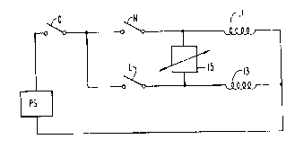
The sole figure is a schematic circuit-diagram
with the windings of a multi-speed motor connected in
accordance with the invention.
Referring specifically to the drawing there is
shown a medium speed winding 11 and a low speed winding 13
of a multi-speed motor not otherwise illustrated. A first
end of medium speed winding 11 is connected to a first end
of power source PS through manually operable switch M and
manually operable common switch C. A first end of low speed
winding 13 is connected to the first end of power source PS
through manually operable switch L and manually operable
common switch C. The other end of power source PS is
connected to the other ends of windings 11 and 13.
Common switch C represents for example, a wall
switch which controls a fan driven by the disclosed multi-
speed motor.
Positive temperature coefficient resistor 15
interconnects the first ends of windings 11 and 13.
Manually operable switches M and L comprise a selection
means for connecting the medium speed and low speed
windings to power source PS. Positive temperature
coefficient resistor 15 comprises a control means which is
operable when low speed winding 13 is connected by the
selection means to the power source for temporarily
connecting medium speed winding 11 to the power source
also. In this way should low speed winding 13 not generate
sufficient torque to rotate the revolving part of the motor
sufficient current would temporarily flow through switches
C and L, positive temperature coefficient resistor 15 and
medium speed winding 11 to overcome the inertia of the
revolving part and start it rotating. As positive
temperature coefficient resistor 15 heats up, as those
skilled in the art will understand, it will present a high
resistance to the flow of current and consequently
effectively cut-off current to medium speed winding 11.

~oo~ ,t83
PHA 21.466 3 14.09.1989
As will be understood should switch M be
closed to connect medium speed winding 11 to power source
PS, current will also flow in low speed winding 13 -
temporarily until positive temperature coefficient resistor
15 heats up sufficiently to present a virtual open circuit
between switch M and low speed winding 13. This, of course,
will guarantee that if medium speed winding 11 does not
alone generate sufficient torque to rotate the revolving
part of the motor that low speed winding 13 adds its torque
lo in starting to insure rotation.
It will also be understood that, should both
switches M and L be closed as well as common switch C, the
motor will rotate at a higher speed than if only medium
speed switch M and common switch C are closed.
With resistor 15, if common switch C is
employed to turn off the motor, stalling is avoided when
switch C is next closed since both windings are connected
to power source PS.
It should be apparent that modifications of
the above will be evident to those skilled in the art and
that the arrangement described herein is for illustrative
purposes and is not to be considered restrictive.

Representative Drawing
A single figure which represents the drawing illustrating the invention.
Administrative Status

2024-08-01:As part of the Next Generation Patents (NGP) transition, the Canadian Patents Database (CPD) now contains a more detailed Event History, which replicates the Event Log of our new back-office solution.

Please note that "Inactive:" events refers to events no longer in use in our new back-office solution.

For a clearer understanding of the status of the application/patent presented on this page, the site Disclaimer , as well as the definitions for Patent , Event History , Maintenance Fee  and Payment History  should be consulted.

Event History

Description Date
Inactive: IPC from MCD 2006-03-11
Time Limit for Reversal Expired 1997-10-30
Application Not Reinstated by Deadline 1997-10-30
Inactive: Abandon-RFE+Late fee unpaid-Correspondence sent 1996-10-30
Deemed Abandoned - Failure to Respond to Maintenance Fee Notice 1996-10-30
Application Published (Open to Public Inspection) 1990-05-02

Abandonment History

Abandonment Date Reason Reinstatement Date
1996-10-30
Owners on Record

Note: Records showing the ownership history in alphabetical order.

Current Owners on Record
PHILIPS ELECTRONICS NORTH AMERICA CORPORATION
Past Owners on Record
JOSEPH STEVEN DROHO
Past Owners that do not appear in the "Owners on Record" listing will appear in other documentation within the application.
Documents

To view selected files, please enter reCAPTCHA code :


To view images, click a link in the Document Description column. To download the documents, select one or more checkboxes in the first column and then click the "Download Selected in PDF format (Zip Archive)" or the "Download Selected as Single PDF" button.

List of published and non-published patent-specific documents on the CPD .

If you have any difficulty accessing content, you can call the Client Service Centre at 1-866-997-1936 or send them an e-mail at CIPO Client Service Centre.


Document
Description 
Date
(yyyy-mm-dd) 
Number of pages   Size of Image (KB) 
Claims 1990-05-01 2 49
Abstract 1990-05-01 1 7
Drawings 1990-05-01 1 6
Representative Drawing 1990-05-01 1 3
Descriptions 1990-05-01 3 105
Fees 1995-09-21 1 74
Fees 1994-09-08 1 75
Fees 1993-09-20 1 62
Fees 1992-09-16 1 50
Fees 1991-09-24 1 52