Note: Descriptions are shown in the official language in which they were submitted.
2002~
MANUFACTURE OF OPTICAL CABLE
This invention relates to the manufacture of
optical cable.
Although optical cable technology is relatively
recent compared to that of electrical telecommunications
cable, optical cables of different constructions have
nevertheless now been developed. In one type of optical
cable, a longitudinally extending core member is provided and
which is formed from extruded plastic material. The core
member has a plurality of longitudinally extending grooves
spaced apart angularly around a longitudinal axis of the core
member and some at least of these grooves contain at least
one optical fiber or, preferably, groups of fibers. More
recently, an optical cable has been developed in which single
optical fibers or groups of optical fibers are housed within
flexible tubes and these tubes are contained within and
extend along the grooves. This structure is as described in
U.S. Patent 4,784,461 granted November 15, 1988 to K. Abe.
In cases where it is desired to provide a water blocking
cable, the completed core including the fiber containing
tubes is then treated, as is normally the case with cores of
all water blocking cables, with a pressurizable viscous
grease or jelly like water blocking materlal which is
intended to fill all the spaces of the grooves unoccupied by
the tubes. However, it is found that after such treatment,
cables of this structure are not satisfactory in repelling
moisture and in preventing the moisture from travelling along
the core.
The present invention provides a method and
apparatus which, in use, seeks to obviate or minimize the
above disadvantages.
Accordingly, the present invention provides a
method of locating a flexible tube and a water blocking
material along a groove in core member during manufacture of
an optical cable comprising passing the core member along a
passline and through a water blocking material application
station and laying a viscous displaceable water blocking
material progressively along and into contact with a base of
the groove at the water blocking material application
200~ S
station; and then laying the flexible tube progressively
along and into the groove and towards the base of the groove
to contact the water blocking material and displace it
upwardly from the base of the groove and between the tube and
sides of the groove so as to fill a space in the base region
of the groove with the water blocking material, the space in
the base region defined below nips provided between the
surface of the tube and sides of the groove.
With the above method, any spaces extending longi-
tudinally of the base regions of the groove are thus filledwith grease to prevent access to and movement of moisture
along the spaces.
Water blocking material may then be provided as
desired to provide water blocking for spaces in the grooves
above the nips, i.e. towards the openings to the grooves,
these spaces above the nips being readily accessible from
outside of the core member with the tube mounted in position.
Water blocking material for this particular purpose may be
additional grease or jelly like material passed under
pressure into these spaces above the nips. Alternatively, a
swellable water blocking material placed around the core
member is provided so as to swell and fill the spaces above
the nips upon contact with the swellable material by water.
In preferred optical cable constructions having
grooves in core members, these grooves extend along the core
members as they extend longitudinally of the core members.
In such cases the method comprises forcing the water blocking
material from a passage and through an outlet into the base
of the groove while controlling the alignment of the outlet
with the groove to ensure the continuous laying of the
material along and into the groove. For this purpose, a
guide member for aligning the outlet with the groove may be
disposed within the groove so as to rotate with the groove
around the longitudinal axis of the core member. The outlet
may be provided in the guide member and directed towards the
base of the groove for forcing the water blocking material
through the outlet and directly into the base. Alterna-
tively, the outlet may be provided in a separate member
Z002~5
dlsposed adjacent to the guide member and along the passline
therefrom so as to be moved by the guide member as it rotates
around the longitudinal axis of the core member.
The present invention also provides according to a
further aspect, an apparatus for locating a flexible tube and
water blocking material along a groove in a core member
during manufacture of an optical cable comprising:- a water
blocking material applicator having a passage for movement of
pressurized displaceable water blocking material, the
applicator having an outlet at a water blocking material
application station, the outlet facing towards a passline for
the core member for laying the water blocking material into
and along the groove; and means downstream along the passline
from the water blocking material applicator for guiding the
flexible tube into and along the groove.
Embodiments of the invention will now be described,
by way of example, with reference to the accompanying
drawings, in which:-
Figure 1 is an isometric view of part of an optical
cable made with apparatus according to the embodiment;
Figure 2 is a diagrammatic side elevational view ofan apparatus according to the embodiment and for manu-
facturing the cable shown in Figure l;
Figure 3 is a side elevational view in cross-
section of a water blocking material applicator forming partof the apparatus shown in Figure 2 and on a larger scale than
Figure 2;
Figure 4 is a side elevational view in cross-
section and to the scale of Figure 3, of a tube laying head
forming part of the apparatus shown in Figure 2;
Figure 5 is a cross-sectional view through a core
member taken along line V-V in Figure 2 and to a larger
scale;
Figure 6 is a cross-sectional view through part of
a core taken along line VI-VI in Figure 4 and shown to a
larger scale than the core member in Figure 5;
Figure 7 is a cross-sectional view through part of
~0~ i4~i
the core taken along line VII-VII in Figure 2 and to the same
scale as Figure 6; and
Figure 8 is a cross-section similar to Figure 7 and
shows a core construction forming a modification of that
shown in Figure 7 and provided upon an apparatus modified
from that of the first embodiment.
An optical cable 10 (Figure 1) which is to be made
by apparatus to be described, comprises a central core member
12 comprising an extruded elongate plastics member 14
surrounding a tensile reinforcing member 16. The core member
12 is formed in conventional fashion and is provided during
its manufacture with a plurality (namely six) of longi-
tudinally extending grooves 18 which are equally spaced-apart
along a longitudinal axis of the core member. These grooves
18 extend in sinuous fashion, as is known, along the core
member and are separated by radially extending ribs 20 which
define sides 22 of the grooves, the ribs extending outwardly
to free ends which lie upon the circumference of a common
circle.
Each groove is occupied by a longitudinally
extending flexible tube 24 formed from a suitable extrudable
plastics material. Each tube carries within it a group 25 of
optical fibers. Each tube lies towards the base of its
respective groove and the diameter of each tube is such that
it converges upon each side 22 of its groove to form nips 26
with the sides while being spaced from the base surface 28 of
the groove as shown in Figure 7. A space in the base region
of each groove, i.e. below the nips 26 and to the base
surface 28, is completely occupied with a suitable grease or
jelly-like water blocking material 29, a thin layer of which
also extends through the nips 26 and outwardly to spaces in
the groove above the nips and outwardly to openings 30 of the
groove.
Immediately surrounding the core member 12 is a
layer 32 of material which is swellable upon contact with
moisture so as to provide a water blocking function. This
layer 32 is of known construction and comprises one or more
substrates which may be of paper or other non-woven material,
2(~)2~S
the substrate carrying particles of swellable material which
may be sodium polyacrylate. As shown in Figure 1, the layer
32 is wrapped completely around the core member and tubes and
while it may extend partly into the openings 30 to the
grooves, it need not, in a dry unswelled condition, com-
pletely fill the space above and lie in contact with the
grease or jelly-like water blocking material 29.
Immediately surrounding the swellable layer 32 is a
conventional corrugated metallic shield 34 with overlapped
ends 36 as shown in Figure 1, the shield being surrounded by
an extruded jacket 38 of suitable polymeric material.
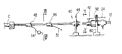
After the manufacture of the core member 12, in
conventional fashion by extrusion, the cable is completed
upon the apparatus 40 according to the embodiment and shown
generally in Figure 2. As shown by Figure 2, the apparatus
40 comprises a water blocking material applicator 42 at a
specific position along a passline for the core member 12,
and means 44 for guiding a plurality (namely six) tubes 24,
one into each of the grooves 18, the means 44 being disposed
downstream of the applicator 42. In order downstream from
the guiding means 44 is disposed an applicator 46 for the
swellable layer 32, an applicator 48 for the corrugated
shield 34, and an extrusion head 50 for forming the jacket
layer 38 around the shield. The applicators 46 and 48 and
the extrusion head are of conventional design and require no
further description.
As shown in greater detail in Figure 3, the
applicator 42 comprises a generally cylindrical head 52 which
has a central passageway 54 and is concentrically mounted
around the passline for the core member 12. The cylindrical
head 52 is rotatably mounted at an upstream end region in
bearings 56 which are carried by a surrounding basically
cylindrical non-rotatable housing 58 which is held at its
upstream end in a vertical frame member 60 attached to a
supporting frame 62. Frame member 60 has a passage 64
aligned with the passage 54 of the head 52. Downstream from
the bearings 56 is disposed a cylindrical chamber 66 for the
passage of pressurized grease or jelly-like water blocking
Z0~26~5
material, the chamber 66 being defined between the rotatable
head and the surrounding housing 58. An inlet 68 is provided
through the housing 58 for passage oE the pressurized water
blocking material into an upstream end region of the chamber
66.
At the downstream end region of the head 52 and at
a water blocking material application station, there are
provided six guide members 70, the guide members extending
inwardly of the passage 54 so as to be disposed within each
of the grooves 18 of the core member. Thus, as the core
member 12 passes through the application station, the grooves
18 rotate at this station around the longitudinal axis of the
core member in sinuous fashion thereby carrying the guide
members 70 with the grooves and causing the rotatable head 52
to rotate in alternate directions around the passline and as
dictated by the angular movement of the grooves 18 around the
core member. Six outlets 72 are provided from the chamber 66
for pressurized water blocking material to cause it be
deposited into each groove and into contact with the base
surface 28 of the groove. Outlets 72 are provided at inner
ends of each of the guide members 70 so as to be disposed
close to the base surfaces of the grooves while being
directed towards them. A seal 73 is provided at the down-
stream end of the head 52 to prevent water blocking material
under pressure from escaping between the head and an end of
the housing 58.
Towards the downstream end of the applicator, there
is disposed an annular electric heater 74 which surrounds the
housing 58 for the purpose of maintaining a sufficiently high
temperature of the water blocking material in the chamber 66
to ensure it has freedom to flow under pressure through the
outlets 72. This heater 74 is particularly useful upon
restart of the use of the apparatus when the water blocking
material may have cooled too far to ensure freedom of flow.
In addition, the applicator 42 is provided with an
air flow directing means 76 disposed upstream from the head
52 for directing air downstream towards the head for cooling
the water blocking material as it is being deposited into the
Z00~6~5
bases of the grooves so as to prevent overheating and
possible degradation of the core member. This air flow
directing means comprises an annulus 78 having an annular air
flow chamber 80 with an inlet 82 for pressurized air and an
annular outlet 84 which is directed in the downstream
direction as is required.
As shown by Flgure 4, the tube guiding means 44
comprises an annular head 86 which is rotatably mounted by
bearings 88 within a vertical frame member 90 extending
upwardly from the machine frame 62. The head 86 has a
coaxial passageway 92 surrounding the passline for the core
member and six guide passages 94 which are equally spaced
apart around the passline and are inclined as shown in Figure
4 from an upstream end towards the downstream end for
directing the tubes 24 into the grooves 18.
In use of the apparatus as shown in Figures 2, 3
and 4, the core member 12 is fed along its feedpath through
the applicator 42, the tube guiding means 44 and then through
the applicators 46 and 48 and through the extrusion head 50.
As the core member proceeds through the applicator 42, the
grease or jelly-like water blocking material is fed under
pressure through the inlet 68 and into the chamber 66 so as
to be forced from the outlets 72. With the guide members 70
located within the grooves 18 so as to rotate with the grease
around the core member at the application station, the water
blocking material is passed in a continuous fashion into each
of the grooves and is directed into the base and against the
base surface 28 of each of the grooves. As may be seen from
Figure 5, the water blocking material is laid against the
base surfaces of the grooves in the form of beads 96 of
substantially circular cross-section.
The core member then carrying the beads 96 of water
blocking material proceeds through the tube guiding means 44
in which the tubes 24, each carrying its own group of optical
fibers 25, are laid along the grooves 18. As can be seen
from Figure 2, the tubes 24 are guided from storage reels
(not shown) towards the head 86 and for this purpose in the
embodiment, the frame member 60 is formed with angularly
20026~5
spaced guide holes 98 through which the tubes pass as they
move towards the inclined guide passages 94 in the head 86.
The tubes pass along the inclined guide passages 94 and are
directed into each of the grooves 18, the core member 12
during its forward movement drawing the tubes into the
grooves from a storage source upstream (not shown). For the
purpose of laying the tubes into the grooves, guides are not
required in the head 86 for causing rotation of the head with
the grooves around the core member as the tubes themselves
are sufficiently stiff to cause rotation of the head in the
appropriate fashion as the tubes move into the grooves.
The drawing action of the core member upon the
tubes combined with the movement of the grooves around the
core member cause the tubes to be pulled down into their
respective grooves so that they approach both the convergent
sides of the grooves and the beads 96 in the bases of the
grooves. The diameters of the beads are such that each bead
is contacted by its associated tube as the downward movement
of the tube progresses so that this downward movement causes
a certain quantity of the water blocking material to be
displaced outwardly towards the entrance of the groove and
around both sides of the tube. The water blocking material
is displaced through a nip 26 of decreasing width between the
tube and each side 22 of the groove as the tube moves
downwardly as shown in Figure 6, until in a final position of
each tube as shown in Figure 7, a base region downwardly from
the nips 26 is completely filled with the water blocking
material 29. This material extends also as a thin film
through each nip and occupies some of the space at each side
of the tube outwardly of the nips and towards the opening 30
to the groove.
The core member 12 carrying the tubes and the water
blocking material 29 which has been formed from the beads 96
then proceeds through the tape applicator 46 at which
position the swellable layer 32 is formed around the core in
known manner for wrapping layers of tape around cores in the
production of cables. As may be seen from Figure 7, with the
layer 32 in position, the layer may project slightly into the
200~6~S
opening 30 of each of the grooves without contacting the
outer surface of the water blocking material 29 in that
particular groove.
The partially completed cable then passes through
the shield applicator 48 and through the extrusion head 50 to
complete the cable 10 in conventional manner.
In use of the cable 10, when installed in the
ground, the water blocking material 29 and the swellable
layer 32 in combination are completely successful in pre-
venting ingress of moisture and progression of moisture alongthe cable beneath the shield. Although a gap may exist along
each groove between the layer 32 and the water blocking
material 29 (Figure 7), should the layer 32 be contacted by
moisture, then the swellable material immediately increases
in volume so as to contact the water blocking material 29 in
the region of the moisture and provide an effective moisture
block in the outer regions of the grooves. As the remainder
of each groove is completely filled with the water blocking
material 29, both inwardly and outwardly of its respective
tube 24, then moisture is effectively prevented from
travelling along the groove.
It should be noted in particular that the method
and apparatus of the first embodiment and according to the
invention ensure that the base regions of each groove are
completely filled with the grease or jelly-like water
blocking material so that water cannot flow along these base
regions to cause damage to the cable. It should also be
noted that if the swellable layer 32 is contacted by
moisture, it not only swells inwardly into each groove so as
to contact the water blocking material 29 as described, but
also swells outwardly so as to intimately contact the inner
surface of the shield 34 and to fill the corrugations so that
water blocking is effectively ensured between these two
layers.
In a modification of the first embodiment, as shown
in Figure 8, an optical cable is not provided with a swell-
able layer 32 but instead, after the provision of the water
blocking material 29 in each of the grooves, is provided with
201~i45
further deformable grease or jelly-like water blocking
material 100 in the outer regions of the grooves and possibly
around the free ends of the ribs 20. The apparatus for
providing this construction differs :Erom the apparatus of the
first embodiment solely in that the tape applicator 46 is
replaced with a conventional applicator for applying the
water blocking material 100 under pressure to the outside of
the core member. As can be seen from Figure 8 this addition-
al water blocking material 100 engages the water blocking
material 29 and merges with it along an interfacial region
102 in each groove so as to completely block each groove from
moisture ingress and axial movement along the cable.