Language selection

Search

Patent 2002808 Summary

Third-party information liability

Some of the information on this Web page has been provided by external sources. The Government of Canada is not responsible for the accuracy, reliability or currency of the information supplied by external sources. Users wishing to rely upon this information should consult directly with the source of the information. Content provided by external sources is not subject to official languages, privacy and accessibility requirements.

Claims and Abstract availability

Any discrepancies in the text and image of the Claims and Abstract are due to differing posting times. Text of the Claims and Abstract are posted:

  • At the time the application is open to public inspection;
  • At the time of issue of the patent (grant).
(12) Patent: (11) CA 2002808
(54) English Title: DEVICE FOR SAMPLING A CIRCULATING FLUID
(54) French Title: APPAREIL D'ECHANTILLONNAGE D'UN FLUIDE EN CIRCULATION
Status: Expired and beyond the Period of Reversal
Bibliographic Data
(51) International Patent Classification (IPC):
  • G01N 1/20 (2006.01)
  • B01D 35/143 (2006.01)
  • G01N 1/28 (2006.01)
  • G01N 1/40 (2006.01)
(72) Inventors :
  • MULLIS, JAMES E., SR. (Canada)
  • MULLIS, JAMES E., JR. (Canada)
(73) Owners :
  • FLUID LIFE CORPORATION (THE)
(71) Applicants :
  • JAMES E., SR. MULLIS (Canada)
  • JAMES E., JR. MULLIS (Canada)
(74) Agent: DOUGLAS B. THOMPSONTHOMPSON, DOUGLAS B.
(74) Associate agent:
(45) Issued: 1996-02-20
(22) Filed Date: 1989-11-10
(41) Open to Public Inspection: 1991-05-10
Examination requested: 1992-10-22
Availability of licence: N/A
Dedicated to the Public: N/A
(25) Language of filing: English

Patent Cooperation Treaty (PCT): No

(30) Application Priority Data: None

Abstracts

English Abstract


A device is provided for sampling the contents of a
pressurized circulating fluid system of a machine. The device is
incorporated in a parallel fluid circuit and comprises a housing
with an inlet to, and outlet from, a cavity. A filter is received
within the cavity. When the filter becomes clogged, a
differential pressure sensor provides an indication for an
operator to close the inlet to the filter cavity, drain the cavity
by means of a valve, and then remove the filter by removing a
plug. The drained cavity fluid and filter may then be shipped to
a lab for testing and the filter replaced and the inlet to the
cavity reopened.


Claims

Note: Claims are shown in the official language in which they were submitted.

The embodiments of the invention in which an exclusive property
or privilege is claimed are defined as follows:
1. A device for sampling the contents of a pressurized
circulating fluid system comprising:
(a) a housing having a cavity, an inlet to said cavity
for receiving fluid from a pressurized circulating fluid system,
and an outlet from said cavity;
(b) a filter seated in said cavity and interposed
between said inlet and said outlet;
(c) means for sensing the pressure differential between
said inlet and said outlet; and
(d) valve means for draining said cavity to obtain
fluid for analysis and to facilitate removal of said filter.
2. The device of claim 1 including shut off valve means for
closing said inlet to said cavity.
3. The device of claim 2 wherein said cavity comprises an
opening to the exterior of said housing sized to permit passage of
said filter, said opening being sealed by removable plug means.
4. The device of claim 3 wherein said valve means comprise
a bore through said plug means sealed by a removable cap.
5. A device as claimed in claim 4 wherein said means for
sensing the pressure differential between said inlet and said
outlet comprises:
(a) a differential pressure sensing chamber having
passageways communicating with said inlet and said outlet;

(b) a piston within said sensing chamber dividing said
chamber into a portion in fluid communication with said inlet and
a portion in fluid communication with said outlet;
(c) means to urge said piston toward said inlet; and
(d) signal means responsive to the position of said
piston within said sensing chamber.
6. In a pressurized circulating fluid system, a parallel
fluid circuit having a device for sampling the contents of a
pressurized circulating fluid system comprising:
(a) a housing;
(b) a fluid passageway within said housing having an
inlet to receive fluid from a pressurized circulating fluid system
and an outlet wherefrom fluid leaves said housing;
(c) a filter seated in a cavity within said fluid
passageway and interposed between said inlet and said outlet;
(d) means for sensing the pressure differential between
said inlet and said outlet; and
(e) valve means for draining said cavity to obtain
fluid for analysis and to facilitate removal of said filter,
said parallel circuit further comprising a shut-off valve for
cutting off said pressurize circulating fluid system from said
fluid passageway.
7. The system of claim 6 wherein said cavity comprises an
opening to the exterior of said housing sized to permit passage of
said filter, said opening being sealed by removable plug means.

8. The system of claim 7 wherein said valve means comprise
a bore through said plug means sealed by a removable cap.
9. A system as claimed in claim 8 wherein said means for
sensing the pressure differential between said inlet and said
outlet comprises:
(a) a differential pressure sensing chamber having
passageways communicating with said inlet and said outlet;
(b) a piston within said sensing chamber dividing said
chamber into a portion in fluid communication with said inlet and
a portion in fluid communication with said outlet;
(c) means to urge said piston toward said inlet; and
(d) signal means responsive to the position of said
piston within said sensing chamber.

Description

Note: Descriptions are shown in the official language in which they were submitted.


200Z8~8 90348-lRDF bw
DEVICE FOR sArlpLING A CIRCULATING FLUID
This invention relates to a device for sampling the
contents of a pressured circulating fluid system.
To ensure the long life of machinery, it is desirable to
periodically analyse the state of fluid circulating in the
machinery. In this regard, it is known to introduce a valve in
the fluid system from which a fluid sample may be removed for
testing. Particulate matter trapped in the system filter may
provide further information on the state of the fluid in the
system and, accordingly, it is also known to forward the system
filter for testing.
Testing of the system filter suffers the drawback that
filters in heavy equipment are large and awkward to handle.
Further, one must be satisfied with an analysis at periods
dictated by the routine changing of the system filter. This is
for the reason that to require more frequent changings to permit
more frequent analysis would result in additional down time for
the equipment.
Accordingly, there remains a need for apparatus to
facilitate the testing of fluid circulating in a machine which
preferably avoids machine down time.
Accordingly, there is provided a device for sampling the
contents of a pressurized circulating fluid system comprising: a
housing having a cavity, an inlet to said cavity for receiving
fluid from a pressurized circulating fluid system, and an outlet
-- 1 -- ~

~002808 90348-lRDF:bw
from said cavity; a filter seated in said cavity and interposed
between said inlet and said outlet; means for sensing the pressure
differential between said inlet and said outlet; and valve means
for draining said cavity to obtain fluid for analysis and to
facilitate removal of said filter.
In drawings which illustrate example embodiments of the
invention:
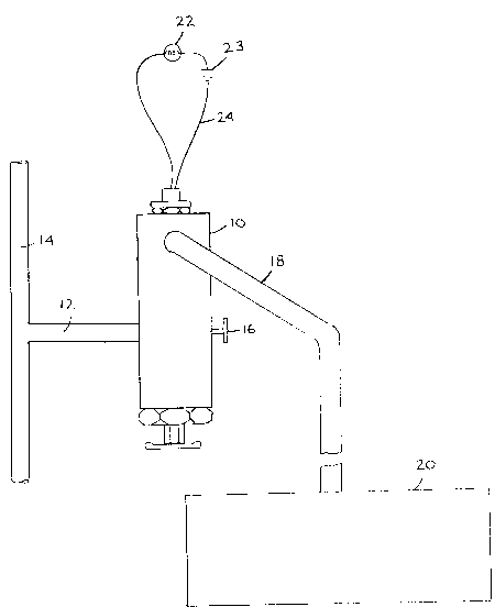
Figure 1 is a partially schematic side view of a portion
of a pressurized circulating fluid system made in accordance with
the present invention, and
Figure 2 is a cross sectional view of a fluid sampling
device made in accordance with the invention.
Referring to Figure 1, a feeder line 12 is tapped off
the main fluid line 14 of the circulating fluid system of a
machine. The feeder line feeds the fluid sampling device 10
detailed in Figure 2. The sampling device 10 incorporates a shut
off valve, the handle for which is shown at 16. An outlet line 18
runs between the fluid sampling device 10 and the fluid sump 20 of
the machine. Thus, the fluid sampling device 10 is in a fluid
circuit which is in parallel with the main circulating fluid
system of the machine. An indicating light 22 and battery 23 are
operatively connected to the sampling device by wire 24.
Turning to Figure 2, the sampling device 10 is seen to
comprise a housing 26 having an inlet 28 (for connection to feeder
line 12 of Figure 1) and an outlet 30 (for connection to outlet
line 18 of Figure 1). An inlet fluid passageway 32 extends
between the inlet and a filter cavity 34, proximate plug 44. An
outlet fluid passageway 36 extends between the reduced diameter

~280~ 90348-lRDF:bw
end 37 of the cavity and the outlet 30.
Cavity 34 is closed by threaded plug 44 which is
threaded into threaded opening 42 of the cavity. Opening 42 is
sized to permit passage of a filter 38. Filter 38 is located
within filter cavity 34 with the open end 33 of the core 31 of the
filter directed toward reduced diameter end 37 of the filter
cavity. The filter is seated against shoulder 39 of the cavity by
spring 40 which acts against one end of the plug 44 and the
filter. O-ring 41 provides a fluid seal between the end of the
filter and shoulder 39. Thus, the filter is interposed between
the inlet 28 and the outlet 30. The threaded plug 44 has a valve
therein comprising central bore 45 sealed by cap 48 which is
threaded into a threaded end of the bore. A handle 49 is affixed
to cap 48.
A differential pressure sensing chamber 50 within the
housing communicates with the inlet 28 (and hence the upstream
side of the filter 38) through passageway 52 and with the outlet
30 (and hence the downstream side of the filter) through
passageways 54a, 54b and 36. A threaded plug 64 closes the
upstream end of the chamber 50. A post 68 extends into the
chamber from plug 64 to just downstream of passage 52. A piston
56 is received within the chamber 50. A piston O-ring 58 provides
a fluid seal between the piston and chamber 50. The piston 56
divides the chamber 50 into an upstream portion 60 and a
downstream portion 62.
Spring return 70 located in the downstream portion 62 of
the chamber 50 urges the piston 56 toward post 68. A magnet 72 is
affixed to the downstream end of the piston. It should be noted

20~2sba 90348-lRDF:bw
that passageway 52 can never be closed off by piston 56 since post
68 extends to just downstream of the passageway.
A magnetically actuated proximity switch 74 is affixed
to threaded shaft 76. Shaft 76 is threaded into threaded opening
77 of housing 26 which is proximate the downstream end 75 of
chamber 50. The threaded shaft 76 is held in place by nuts 78 and
79. The proximity switch 74 is connected to wire 24 to indicating
light 22 and battery 23 (of Figure 1).
Shut off valve handle 16 connects to valve element 80 in
inlet 28.
In operation, in an embodiment of the invention wherein
the fluid is oil, pressurized oil enters inlet 28 of the sampling
device 10 through feeder line 12. So long as shut off valve
element 80 is in an open position, oil flows through fluid
passageway 32 to filter cavity 34. The oil flows through the wall
of the filter to its core 31 and then exits through outlet 30 to
outlet line 18. The filter 38 traps any particulate matter
present in the oil.
The oil pressure in the sampling device 10 upstream and
downstream of filter 38 is communicated to the upstream 60 and
downstream 62 portions of pressure differential sensing chamber 50
by passageways 52 and 54a, 54b, respectively. Pressurized oil in
the upstream portion 60 of chamber 50 urges piston 56 toward the
downstream end 75 of the chamber 50. The spring 70 and oil
pressure in the downstream portion 62 of the chamber provide a
counteracting force. This counteracting force seats piston on
post 68 until the filter clogs sufficiently that the reduced
downstream pressure and the force provided by the spring do not
-- 4

Z0~2808 90348-lRDF:bw
counteract the upstream pressure, whereupon the piston moves
toward end 75 to a new equilibrium point. When piston 56 reaches
a pre-set distance from the proximity switch 74, the magnetic flux
from magnet 72 actuates the proximity switch and lamp 22 is
illuminated, signalling the operator to sample the oil.
The differential presssure at which the lamp is
illuminated can be selected by altering the distance shaft 76 is
threaded into threaded opening 77, which adjusts the proximity of
the proximity switch 74 to end 75 of chamber 50. Further, this
differential pressure may be controlled by selecting a spring 70
having an appropriate spring constant.
~ hen the operator has received a signal indicating that
a sample should be taken, valve element 80 is positioned to close
passageway 32 to isolate the filter cavity 34 from the oil
circulating system and from the differential pressure chamber 50.
It should be noted that this does not interrupt the oil
circulating system thus allowing for continued operation of the
machine throughout the sampling process. Handle 49 is then
turned, to remove cap 48 and drain filter cavity 34 into an oil
sample vial which the operator holds beneath bore 45. Plug 44 can
then be removed in order to allow removal of spring 40 and filter
38. The filter and oil sample may then be forwarded for analysis.
A fresh filter may be inserted into the filter cavity with spring
40 following and the plug 44 and cap 48 replaced whereupon valve
element 80 may be reopened which brings the smpling device into
operation once more.

~Q2808 90348-lRDF:bw
It will be obvious to one skilled in the art that the
proximity switch 74 could be modified to close when the piston
moved a preset distance away from switch 74 in which case the
proximity switch would be mounted at the other end of chamber 50.
It will also be apparent the valve in plug 44 for draining cavity
34 could be replaced by a separate valve with a valve bore
communicating with cavity 34 proximate the base of the cavity.

Representative Drawing
A single figure which represents the drawing illustrating the invention.
Administrative Status

2024-08-01:As part of the Next Generation Patents (NGP) transition, the Canadian Patents Database (CPD) now contains a more detailed Event History, which replicates the Event Log of our new back-office solution.

Please note that "Inactive:" events refers to events no longer in use in our new back-office solution.

For a clearer understanding of the status of the application/patent presented on this page, the site Disclaimer , as well as the definitions for Patent , Event History , Maintenance Fee  and Payment History  should be consulted.

Event History

Description Date
Inactive: Reversal of expired status 2012-12-02
Time Limit for Reversal Expired 2009-11-10
Inactive: Adhoc Request Documented 2009-01-29
Letter Sent 2008-11-10
Inactive: IPC from MCD 2006-03-11
Grant by Issuance 1996-02-20
Request for Examination Requirements Determined Compliant 1992-10-22
All Requirements for Examination Determined Compliant 1992-10-22
Application Published (Open to Public Inspection) 1991-05-10

Abandonment History

There is no abandonment history.

Maintenance Fee

The last payment was received on 

Note : If the full payment has not been received on or before the date indicated, a further fee may be required which may be one of the following

  • the reinstatement fee;
  • the late payment fee; or
  • additional fee to reverse deemed expiry.

Please refer to the CIPO Patent Fees web page to see all current fee amounts.

Fee History

Fee Type Anniversary Year Due Date Paid Date
MF (patent, 8th anniv.) - small 1997-11-10 1997-11-06
MF (patent, 9th anniv.) - small 1998-11-10 1998-10-06
MF (patent, 10th anniv.) - small 1999-11-10 1999-09-29
MF (patent, 11th anniv.) - small 2000-11-10 2000-10-24
MF (patent, 12th anniv.) - small 2001-11-12 2001-10-15
MF (patent, 13th anniv.) - small 2002-11-11 2002-10-31
MF (patent, 14th anniv.) - small 2003-11-10 2003-10-21
MF (patent, 15th anniv.) - small 2004-11-10 2004-09-01
MF (patent, 16th anniv.) - small 2005-11-10 2005-10-04
2006-10-03
MF (patent, 17th anniv.) - small 2006-11-10 2006-10-03
MF (patent, 18th anniv.) - standard 2007-11-12 2007-10-31
MF (application, 2nd anniv.) - small 02 1991-11-11
Owners on Record

Note: Records showing the ownership history in alphabetical order.

Current Owners on Record
FLUID LIFE CORPORATION (THE)
Past Owners on Record
JAMES E., JR. MULLIS
JAMES E., SR. MULLIS
Past Owners that do not appear in the "Owners on Record" listing will appear in other documentation within the application.
Documents

To view selected files, please enter reCAPTCHA code :


To view images, click a link in the Document Description column. To download the documents, select one or more checkboxes in the first column and then click the "Download Selected in PDF format (Zip Archive)" or the "Download Selected as Single PDF" button.

List of published and non-published patent-specific documents on the CPD .

If you have any difficulty accessing content, you can call the Client Service Centre at 1-866-997-1936 or send them an e-mail at CIPO Client Service Centre.


Document
Description 
Date
(yyyy-mm-dd) 
Number of pages   Size of Image (KB) 
Abstract 1996-02-23 1 18
Cover Page 1996-02-23 1 16
Claims 1996-02-23 3 85
Drawings 1996-02-23 2 29
Representative Drawing 2000-02-25 1 7
Descriptions 1996-02-23 6 208
Maintenance Fee Notice 2008-12-22 1 171
Fees 2003-10-21 1 25
Fees 1998-10-06 1 38
Fees 2002-10-31 1 29
Fees 1997-11-06 1 43
Fees 2004-09-01 1 30
Fees 2005-10-04 1 26
Fees 2006-10-03 1 25
Fees 2007-10-31 1 25
Fees 1996-09-05 1 58
Fees 1994-10-11 1 51
Fees 1995-08-21 1 48
Correspondence 1993-10-05 1 36
Fees 1992-10-22 1 56
Fees 1993-09-17 1 43
Fees 1991-11-08 1 132
Correspondence 1992-09-10 1 57
Courtesy - Office Letter 1992-02-03 1 22
Courtesy - Office Letter 1992-03-02 1 26
PCT Correspondence 1992-08-31 2 96
Courtesy - Office Letter 1993-02-15 1 64
Courtesy - Office Letter 1993-02-15 1 65
Prosecution correspondence 1992-10-22 1 34
Courtesy - Office Letter 1993-03-19 1 44
PCT Correspondence 1995-12-07 1 40
Prosecution correspondence 1993-04-15 1 31