Language selection

Search

Patent 2002878 Summary

Third-party information liability

Some of the information on this Web page has been provided by external sources. The Government of Canada is not responsible for the accuracy, reliability or currency of the information supplied by external sources. Users wishing to rely upon this information should consult directly with the source of the information. Content provided by external sources is not subject to official languages, privacy and accessibility requirements.

Claims and Abstract availability

Any discrepancies in the text and image of the Claims and Abstract are due to differing posting times. Text of the Claims and Abstract are posted:

  • At the time the application is open to public inspection;
  • At the time of issue of the patent (grant).
(12) Patent: (11) CA 2002878
(54) English Title: VALVE FOR INTERNAL COMBUSTION ENGINES
(54) French Title: SOUPAGE POUR MOTEUR A COMBUSTION INTERNE
Status: Expired and beyond the Period of Reversal
Bibliographic Data
(51) International Patent Classification (IPC):
  • F01L 03/00 (2006.01)
  • F01L 03/20 (2006.01)
(72) Inventors :
  • HOLMER, ERNST (Sweden)
(73) Owners :
  • AB VOLVO
(71) Applicants :
  • AB VOLVO (Sweden)
(74) Agent: SMART & BIGGAR LP
(74) Associate agent:
(45) Issued: 1999-06-01
(22) Filed Date: 1989-11-14
(41) Open to Public Inspection: 1990-05-15
Examination requested: 1996-11-01
Availability of licence: N/A
Dedicated to the Public: N/A
(25) Language of filing: English

Patent Cooperation Treaty (PCT): No

(30) Application Priority Data:
Application No. Country/Territory Date
8804120-7 (Sweden) 1988-11-15

Abstracts

English Abstract


The invention relates to a valve which is intended for
internal combustion engines and which comprises a valve-head
(2) which has formed thereon a circular abutment surface
for sealing coaction with a valve seat (9). The
valve-head (2) has connected therewith a valve-stem (3) by
means of which the valve is moveably journalled in a
valve-guide (10). According to the invention, the valve-head
(2) has a relatively small wall-thickness, and the
valve-stem (3) has provided thereon a collar (16) which on
the side thereof distal from the valve-plate (2) has an
abutment surface (17) for abutment with a fixed abutment
surface.


French Abstract

.

Claims

Note: Claims are shown in the official language in which they were submitted.

THE EMBODIMENTS OF THE INVENTION IN WHICH AN EXCLUSIVE
PROPERTY OR PRIVILEGE IS CLAIMED ARE DEFINED AS FOLLOWS:
1. A valve intended for internal combustion engines and
including a valve-head having a circular surface for sealing
coaction with a valve seat, and further comprising a valve-stem
which is joined to the valve-head and which is movably
journalled in a valve-guide, characterized in that the valve-head
has a relatively small wall-thickness in cross-section;
and in that the valve-stem is provided with a collar which
presents on the side thereof remote from the valve-head an
abutment surface intended for abutment with a fixed abutment
surface.
2. A valve according to Claim 1, characterized in that
the valve-head, on the side thereof remote from the valve-stem
is configured with a convex part of substantially constant
wall-thickness.
3. A valve according to Claim 2, characterized in that
the convex part of the valve-head forms a ring which encircles
a central recess on the side remote from the valve-stem.
4. A valve according to Claim 2 or Claim 3,
characterized in that the convex part of the valve-head has a
curvature such that the forces which act on the valve during

operation will essentially generate compressive stresses in
solely the convex part.
5. A valve according to any one of Claims 1-4,
characterized in that the abutment surface intended for
abutment with the collar on the valve-stem comprises the end
of the valve-guide.

Description

Note: Descriptions are shown in the official language in which they were submitted.


2(~02878
A valve for internal combustion engines
The present invention relates to a valve which is intended
for internal combustion engines and which includes a
valve-head which has provided thereon a circular surface
for sealing coaction with a valve seat, and which further
comprises a valve-stem which is joined to the valve-head
and by means of which the valve is moveably journalled in
a valve guide.
Poppet valves are used in almost all internal combustion
engines for controlling communication between the combus-
tion-chamber and inlet and outlet ducts. The valves are
opened and closed by means of valve mechanisms which nor-
mally include a cam shaft which is provided with cams for
activation of the individual valves. Efforts are made with
modern engines to achieve higher efficiencies, and conse-
quently it is of interest to improve the exchange of gas
between the cylinder combustion-chamber and the inlet and
outlet ducts. It is therefore desirable that the valves
will open and close as quickly as possible, so as to redu-
ce the throttling effect which occurs when the valve is
partially open.
In order to ensure that the valve can be opened rapidly,
it is necessary to provide the cams with steep camming
surfaces and to apply large forces. These forces result in
high pressures on the cam-surfaces, which in turn may
result in mechanical-strength problems. In order to ensure
that the valve will close rapidly, it is necessary to use
powerful valve-springs, such springs resulting in powerful
forces and high stresses when the valve-head strikes the
valve-seat which also results in mechanical-strength
problems. These problems are made worse by the fact that
in order to enable the valves to withstand the mechanical
stresses and strains to which they are subjected, the

7 ~ ~
valves have been made thicker, therewlth resultlng ln a
greater mass, whlch ln turn results ln hlgher lnertla forces,
partlcularly at hlgh englne speeds. These problems are
further accentuated wlth larger valve-dlameters, partlcularly
wlth a view to the fact that the valve must be capable of
wlthstanding the large forces whlch occur as a result of
combustion pressure ln the combustlon chamber.
The ob~ect of the present lnventlon ls to provldé a
valve wlth whlch the aforesald drawbacks are avolded and whlch
wlll be relatlvely llght ln welght, even when the valve-head
has a large dlameter. In accordance wlth the lnventlon there
ls provided a valve lntended for lnternal combustlon englnes
and includlng a valve-head havlng a clrcular surface for
seallng coactlon wlth a valve seat, and further comprlslng a
valve-stem whlch is ~olned to the valve-head and whlch ls
movably ~ournalled ln a valve-gulde, characterlzed ln that the
valve-head has a relatlvely small wall-thlckness ln cross-
sectlon; and ln that the valve-stem ls provlded wlth a collar
whlch presents on the slde thereof remote from the valve-head
an abutment surface lntended for abutment wlth a flxed
abutment surface.
The lnvention will now be descrlbed ln more detall
wlth reference to the accompanylng drawlng, ln whlch
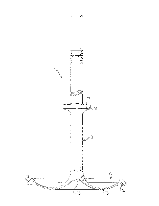
Flg. 1 ls a partly cut-away slde-vlew of a flrst
embodlment of a valve constructed ln accordance wlth the
lnvention;
63182-57

8 7 ~
2a
Flg. 2 ls a sectlonal vlew of a part of an lnternal
combustlon englne provlded wlth an lnventlve valve accordlng
to Flg. l; and
Flg. 3 ls a sectlonal vlew of part of a valve constructed
ln accordance wlth a second embodlment of the lnventlon.
The drawlng lllustrates a valve 1 whlch comprlses a
valve-head 2 to whlch there ls ~olned a valve-stem 3. Flg. 2
shows the valve 1 fltted to an lnternal combustlon englne, of
whlch there ls shown solely part of a cyllnder head 4,
together wlth a duct 5, part of a cyllnder 6 and a plston 7
mounted ln the cyllnder. The cyllnder head 4, the cyllnder 6
and the plston 7 together deflne a combustlon chamber 8 lnto
whlch the duct 5 opens. The valve 1 ls lntended to control
the exchange of gas between the duct 5 and the
c~ 63182-57

3 ~ 7~ ~
combustion chamber 8. To this end, the valve-head 2 is
intended to coact with a valve seat 9 located at the out-
let orifice of the duct 5, and the valve-stem 3 is guided
in a valve guide 10 rigidly mounted on the cylinder head
4. The valve 1 is operated by means of a valve mechanism
of known kind, of which only a double valve-spring 11 is
shown in the drawing.
As will be seen in particular from Fig. 1, the valve-head
2 has only a small thickness between the centre part of
the valve-head, where the valve-stem joins the head, and
the outer periphery of the head, said outer periphery
being configured with an oblique circular abutment surface
12 intended for coaction with the valve seat 9. Because of
the thinness of the valve-head, the weight of the valve as
a whole will be small, and consequently the valve-opening
and valve-closing forces which need be exerted by the
valve mechanism will also be small. In order to enable the
valve-head 2 to withstand the forces which act on the
valve-head during operation, the valve-head 2 is provided,
in accordance with the embodiment illustrated in Figure 1,
with a part 13 which is convex in a direction away from
the valve-stem 3. The convex part 13 is configured as a
circular part located between a thicker part 14 adjacent
the abutment surface 12 and the central part of the valve-
head 2 at which the valve-stem 3 joins said head. This
central part therewith has the form of a recess 15.
The valve-stem 3 is provided between its two ends with a
circular collar 16, which has a substantially flat abut-
ment surface 17 on the side thereof remote from the valve-
head 2. When the valve 2 occupies its closed position, the
abutment surface 17 will lie against a rigid abutment sur-
face, which may either be configured on the cylinder head
or some part connected thereto. In the case of the Figure
2 embodiment, this abutment surface consists in the
63182-57

20028~78
end-surface lOa of the valve guide 10. When the abutment
surface 17 abuts the end-surface lOa and the abutment 12
abuts the valve-seat 9, the forces acting on the valve-
head 2 will be distributed between the abutment surfaces
12 and 17, thereby enabling the convex part 13 of the
valve-head to be made very thin. In this respect, the con-
vex part 13 is preferably curved in a manner such that the
forces which act on the valve in operation will essen-
tially generate compressive stresses solely in the mate-
rial of the convex part 13. This will enable the material
from which the valve-head 2 is made to be utilized to a
maximum, particularly the material in the convex part 13.
Consequently, the valve-head 2 will be much lighter in
weight than the valve-head of a corresponding conventional
valve.
In the case of the inventive valve, it is important that
the valve-head 2 and the valve-stem 3 is so configured
that the valve will function satisfactorily under all
conditions, irrespective of prevailing valve temperatures
and the temperatures of the parts coacting therewith. This
implies that the distance between the abutment surfaces 12
and 17 must always correspond to the distance between the
valve-seat 9 and the fixed abutment surface lOa, so that
contact is achieved, both between the abutment surface 12
and the valve-seat 9, and between the abutment surface 17
and the fixed abutment-surface lOa, without appreciable
deformation of any part of the valve.
The aforesaid temperature-independency of the inventive
valve can be accomplished by appropriate curvature of the
convex part 13 of the valve-head 2 and by suitable adapta-
tion of the wall-thickness thereof. It is also conceivable
in this regard to produce part of the valve-stem 3 from a
material which has a coefficient of thermal expansion
different to that of the remainder of said valve-stem.

2002878
Fig. 3 illustrates an alternative embodiment of a valve
constructed in accordance with the invention. This Figure
is a sectional view of solely one half of a valve-head 18
and a valve-stem 19 joined to the head. The valve of this
embodiment is similar to the valve of the Fig. 1 embodi-
ment, with the exception that the valve-head 18 of Fig. 3
consists of a hollow body. this hollow body has a part 20
which is convex in a direction from the valve-stem 19 and
which extends over the whole of the valve surface expand-
ing from the valve-stem 19 and which connects at its peri-
phery with an abutment surface 21 intended for coaction
with a valve-seat, e.g. the valve-seat 9 shown in fig. 2.
The convex part 20 of the valve embodiment shown in Fig. 3
is also curved in a manner such that the forces acting on
the valve during operation will essentially generate com-
pressive stresses solely in the convex part 20.
The invention is not restricted to the aforedescribed
embodiments, since modifications can be made thereto with-
in the scope of the following claims.

Representative Drawing
A single figure which represents the drawing illustrating the invention.
Administrative Status

2024-08-01:As part of the Next Generation Patents (NGP) transition, the Canadian Patents Database (CPD) now contains a more detailed Event History, which replicates the Event Log of our new back-office solution.

Please note that "Inactive:" events refers to events no longer in use in our new back-office solution.

For a clearer understanding of the status of the application/patent presented on this page, the site Disclaimer , as well as the definitions for Patent , Event History , Maintenance Fee  and Payment History  should be consulted.

Event History

Description Date
Inactive: IPC from MCD 2006-03-11
Time Limit for Reversal Expired 2004-11-15
Letter Sent 2003-11-14
Grant by Issuance 1999-06-01
Inactive: Cover page published 1999-05-31
Inactive: Final fee received 1999-02-22
Pre-grant 1999-02-22
Letter Sent 1998-09-29
Notice of Allowance is Issued 1998-09-29
Inactive: Status info is complete as of Log entry date 1998-09-22
Inactive: Application prosecuted on TS as of Log entry date 1998-09-22
Inactive: Approved for allowance (AFA) 1998-08-28
Request for Examination Requirements Determined Compliant 1996-11-01
All Requirements for Examination Determined Compliant 1996-11-01
Application Published (Open to Public Inspection) 1990-05-15

Abandonment History

There is no abandonment history.

Maintenance Fee

The last payment was received on 1998-10-21

Note : If the full payment has not been received on or before the date indicated, a further fee may be required which may be one of the following

  • the reinstatement fee;
  • the late payment fee; or
  • additional fee to reverse deemed expiry.

Patent fees are adjusted on the 1st of January every year. The amounts above are the current amounts if received by December 31 of the current year.
Please refer to the CIPO Patent Fees web page to see all current fee amounts.

Fee History

Fee Type Anniversary Year Due Date Paid Date
MF (application, 8th anniv.) - standard 08 1997-11-14 1997-10-20
MF (application, 9th anniv.) - standard 09 1998-11-16 1998-10-21
Final fee - standard 1999-02-22
MF (patent, 10th anniv.) - standard 1999-11-15 1999-10-18
MF (patent, 11th anniv.) - standard 2000-11-14 2000-10-18
MF (patent, 12th anniv.) - standard 2001-11-14 2001-10-17
MF (patent, 13th anniv.) - standard 2002-11-14 2002-10-17
Owners on Record

Note: Records showing the ownership history in alphabetical order.

Current Owners on Record
AB VOLVO
Past Owners on Record
ERNST HOLMER
Past Owners that do not appear in the "Owners on Record" listing will appear in other documentation within the application.
Documents

To view selected files, please enter reCAPTCHA code :


To view images, click a link in the Document Description column. To download the documents, select one or more checkboxes in the first column and then click the "Download Selected in PDF format (Zip Archive)" or the "Download Selected as Single PDF" button.

List of published and non-published patent-specific documents on the CPD .

If you have any difficulty accessing content, you can call the Client Service Centre at 1-866-997-1936 or send them an e-mail at CIPO Client Service Centre.


Document
Description 
Date
(yyyy-mm-dd) 
Number of pages   Size of Image (KB) 
Abstract 1999-05-30 1 16
Drawings 1999-05-30 2 26
Representative Drawing 1999-05-30 1 5
Claims 1999-05-30 2 43
Descriptions 1999-05-30 6 226
Commissioner's Notice - Application Found Allowable 1998-09-28 1 163
Maintenance Fee Notice 2004-01-11 1 174
Correspondence 1999-02-21 1 39
Fees 1996-10-29 1 80
Fees 1995-10-30 1 85
Fees 1993-10-24 1 52
Fees 1994-10-25 1 69
Fees 1992-10-21 1 35
Fees 1991-10-23 1 27
Courtesy - Office Letter 1990-04-03 1 53
Prosecution correspondence 1996-10-31 1 39
Courtesy - Office Letter 1996-11-28 1 47
Prosecution correspondence 1998-07-19 2 45