Note: Descriptions are shown in the official language in which they were submitted.
200X938
FIELD OF THE INVENTION
The present invention relates to a device
for use with an underground drainage and irrigation
network formed of a main conduit line and of
adjacently disposed, water permeable secondary
conduit lines with a view to controlling the
underground water table level.
BACKGROUND OF THE INVENTION
In order to facilitate access to fields by
heavy agricultural machinery during the spring and
fall seasons, the ground of these fields is usually
drained by an underground system. One widely used
method consist in disposing drainage pipes made of
plastic or other suitable material in the ground
according to specific patterns. These pipes are
usually buried at a depth of approximately 0,9 to 2
meters with a tilt angle between 0,01% and 2% and are
spaced 10 to 50 meters apart.
When the flow of water in the drainage
pipes is not controlled, it varies mainly as a
function of the height of water directly above the
pipes. Therefore, if the flow is not controlled
after a given precipitation, the drainage system will
evacuate water in the ground until the level of
underground water reaches the level of the drainage
pipes.
Many studies have shown that uncontrolled
drainage systems cause dehydration of the soil during
the crucial growing periods if no sufficient
ZOOZ938
replenishment is provided by precipitations, such as
rain. Indeed, since pipes are buried at a level
lower than the level of water necessary for optimal
plant (or crop) growth and since they drain the soil
until the level of water is approximately equal to
their level of burial, they are often prejudicial to
such growth.
Numerous examples of drainage and/or
irrigation control systems designed to overcome the
above-mentioned problems exist. Some of them are
found described in Canadian Patent no. 1,088,330 and
U.S. Patent nos. 4,621,945, 3,559,408 and 3,368,355.
Some most widely used control chambers are shown in
U.S. Patent nos. 4,621,945 and 3,368,355.
However, these types of control chambers,
while limiting the risks of excessive drainage,
create a risk of underdrainage. Control chambers are
usually adapted to drainage systems and are designed
by taking into consideration fixed parameters, such
as the hydraulic conductivity of the soil, the
drainage coefficient, etc. When added to existing
systems, the control chambers, whether of the
"overflow" or "float" type, create a virtual drainage
depth which is higher than the depth for which the
system is designed. This situation can lead to the
deterioration of crop since most roots are vulnerable
to deprivation of oxygen by excessive water
accumulation.
Z002938
OBJECTS AND STATEMENT OF THE INVENTION
It is an object of the present invention to
overcome the above-described problems associated with
presently used control devices for underground
drainage and/or irrigation systems. This is achieved
by providing a control device for soil drainage
and/or irrigation which takes into account the level
of the underground water table between two drainage
and/or irrigation conduit lines instead of that
directly above these lines.
It is a further object of the present
invention to provide a control device which is
readily adaptable to existing drainage and/or
irrigation systems, which is mechanically simple and
which can be manufactured at a relatively low cost.
More specifically, in accordance with a
first aspect of the invention, there is provided a
control device for use with an underground irrigation
network formed of a main conduit line and of
adjacently disposed water permeable secondary conduit
lines, comprising:
- a head control stand means disposed at a
predetermined location of the network, which stand
means comprising a vertically extending housing
defining a water-receiving chamber, water level
sensing means being mounted in the chamber;
- valve means associated with the stand
means and mounted on a water supply pipe for
2002938
supplying water to the network, the valve means being
actuatable in response to the water level sensing
means; and
- water table level measuring means
disposed between two adjacent secondary conduit lines
of the network, the measuring means being remotely
associated with the water level sensing means in the
stand means to open or close the valve means and
thereby maintain an underground water table between
the two adjacent lines at a level adequate for
optimal plant growth.
Advantageously, the valve means are
operatively connected to the sensing means in the
chamber, the water table level measuring means is in
fluid communication with the chamber, and these
measuring means include water-collecting means having
a water permeable section disposed between two
adjacent secondary conduit lines of the network and
water impermeable section connected to the chamber
allowing underground water collected in the water
permeable section to be received in the chamber to
thereby influence the water level sensing means into
operating the valve means to open or close and
thereby maintain an underground water table between
the two adjacent secondary conduit lines at a level
adequate for optimal plant growth.
Preferably, the water-collecting means
comprises an underground duct, the water permeable
section comprises an end, perforated portion of the
duct disposed between the two adjacent secondary
conduit lines, and the water impermeable section
200;~
comprises a non perforated portion of the duct
interconnecting the perforated duct portion and the
chamber.
According to another aspect of the present
invention there is provided a control device for use
with an underground drainage and irrigation network
formed of a main conduit line and of adjacently
disposed water permeable secondary conduit lines,
comprising:
- a head control stand means disposed at a
predetermined location of the network, the stand
means comprising at least one vertically extending
housing defining a water-receiving chamber, water
level sensing means being mounted in this chamber;
- first drainage valve means mounted in
the main line and associated with the stand means,
the first valve means being operatively connected to
the water level sensing means in the chamber;
- second irrigation valve means associated
with the stand means and mounted on a water supply
pipe for supplying water to the network, the second
valve means being also operatively connected to the
water level sensing means in the chamber; and
- water table level measuring means in
fluid communication with the chamber, the measuring
means including water-collecting means having a water
permeable section disposed between two adjacent
secondary conduit lines of the network and a water
impermeable section connected to the chamber allowing
200293~
underground water collected in the water permeable
section to be received in the chamber to thereby
influence the water level sensing means into
operating the first and second valve means to open or
close and thereby maintain underground water table
between the two adjacent water permeable secondary
conduit lines at a level adequate for optimal plant
growth.
Other objects and further scope of
applicability of the present invention will become
apparent from the detailed description given
hereinafter. It should be understood, however, that
this detailed description, while indicating preferred
embodiments of the invention, is given by way of
illustration only, since various changes and
modifications within the spirit and scope of the
invention will become apparent to those skilled in
the art.
BRIEF DESCRIPTION OF THE DRAWINGS
Figure 1 is a perspective schematic view of
an underground drainage network using a drainage
control device made in accordance with the present
invention;
Figure 2 is an elevational view of the
drainage control device of Figure l;
Figure 3 is an elevational view of an
irrigation control device in accordance with the
present invention for use with the network of Figure
l;
200293~3
Figure 4 is a perspective schematic view of
an underground drainage and irrigation network using
the drainage and irrigation control devices of
Figures 2 and 3; and
Figures 5 and 6 are elevational views of a
drainage and irrigation device according to the
invention for use with the underground network of
Figure 1.
DETAILED DESCRIPTION OF THE PREFERRED EMBODIMENTS
Referring to Figures 1 and 2 of the
appended drawings, there is shown a portion of an
underground drainage and irrigation network that
includes a main conduit line 10 and of two adjacently
disposed secondary, inclined conduit lines 12 and 14
connected at one end thereof to the line 10. The
lines 12 and 14 are parallel to each other, but they
are perpendicular to the main line 10. The lines 10,
12 and 14 are advantageously made of plastic piping
material, the plastic material of the conduit lines
10 and 12 being perforated to be water permeable.
For drainage purposes, water in the ground
is collected by the perforated conduit lines 12 and
14 and is directed toward the main line 10. A valve
in the form of a rubber door 18 is provided in the
main line 10 allowing the water collected to be
discharged, when desired, in a ditch 16.
A first aspect of the present invention is
concerned with a means 20 for opening or closing the
2002~3~
valve 18 to thereby control the water table level 22
and allow for optimal plant growth. An important
feature of the present invention is that this water
table level is measured between the two perforated
lines 12 and 14 preferably at equidistance therefrom.
One form of such means 20 is illustrated in
Figure 2 and comprises a pair of hollow and
vertically extending head control stands 24 and 26
arranged side-by-side. The drainage head control
stand 24 consist of a chamber 28 in which a float 30
is provided. The lower part of the chamber has an
opening to which is connected a duct 32 which is
imperforated except in one area 32a (Figure 1)
situated equidistantly between lines 12 and 14.
The water collected in the perforated area
32a of the duct is conducted through gravity to the
chamber 28 causing the float 30 to raise. It should
be pointed out here that the level of water in the
control stand 24 is function of the level 22 (Figure
1) of the underground water table between the lines
12 and 14. In the embodiment illustrated, the float
30 is mounted on a shaft 36, the upper end of which
is connected to the door 18 through a rope 40 itself
mounted on a pulley 42.
The height of the float 30 within the stand
24 is adjustable. For example shaft 36 is provided
with a threaded portion 36a allowing for this height
adjustment.
When the water collected in the chamber 28
reaches a height causing the float 30 to raise, the
Z002938
upper end of the shaft 36 pulls the rope 40 to rotate
the pulley 42 and open the door 18. The door 18 is
opened until the water table returns to a desired
level for optimal plant growth.
In Figures 1 and 2, a means 20 for opening
or closing the valve 18 is illustrated. The means 20
can however be replaced, as shown in Figure 3, by a
means 40 for controlling irrigation of the ground
through the underground lines 10, 12 and 14.
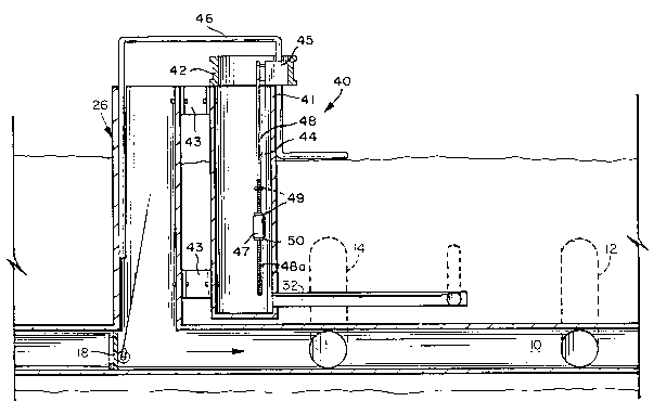
The means 40 again comprises the head
control stand 26 communicating at the lower end
thereof with the main line 10. It also comprises a
hollow and vertically extending head control stand 41
attached to the stand 26 adjacent the latter (see
brackets 43 in Figure 3). The stand 41 consist of a
chamber 44 having a lower opening connected to the
duct 32 as explained above relative to stand 24
(Figure 2).
An upper collar 42 is removably mounted on
the stand 41, and a valve 45 is secured to the inside
of collar 42. Valve 45 is mounted on a water supply
pipe 46 and is operated by a float 47 responsive to
the level of water in stand 41. For that purpose,
float 47 is connected to the valve 45 through a metal
rod 48 with its lower portion 48a threaded. The
float 47 has a central hole to receive the threaded
rod portion 48a. A pair of nuts 49 and 50 is engaged
with the threaded rod portion 48a; nut 49 serves to
close valve 45 while nut 50 serves to open valve 45.
These nuts enable adjustment of the on and off
positions of the float 47 along rod 48. When the
200~938
nuts 49 and 50 both rest on either side of the float
47, valve 45 is operating in a modulating mode. The
spacing between the nuts 49 and 50 can also be
increased to operate valve 45 in a second range mode
(see nut 49 illustrated in dashed lines in Figure 3).
In this second mode, the difference between the water
levels in the stand 41 at which valve 45 is closed
and opened is increased. Accordingly, the position
of the nuts 49 and 50 on the threaded rod portion 48a
can be easily adjusted in accordance with the
requirements of the intended application.
As can be appreciated, the assembly
including valve 45, rod 48 and float 47 can be
removed from the stand 41 as the collar 42 is
removed.
In an underground drainage and irrigation
installation as illustrated in Figure 4, both stands
24 and 41 are provided. Drainage and irrigation can
then be simultaneously controlled. More
specifically, valve 45 supplies water, for irrigation
purposes, in the stand 26 through the pipe 46 in
relation to the level of water detected by float 47
in control stand 41, while float 30 controls, for
drainage purposes, opening of the door 18 in response
to the level of water in stand 24. Again, the float
30 opens the door 18 through the shaft 36, pulley 42
and rope 40 passing through hollow stand 26.
Also, as illustrated in Figures 5 and 6,
the float 30, shaft 36, valve 45, rod 48 and float 47
can be placed on or in a single hollow and vertically
extending control stand 51. Stand 51 consists of a
Z002~
chamber 52 with a lower opening connected to duct 32.
In the latter embodiment, the float 30, positioned
above float 47, is formed with a vertical opening 53
allowing passage of the rod 48 and float 47. Also,
collar 42 may be formed with guiding means (not
shown) in which the shaft 36 slides along the
longitudinal, vertical axis of stand 51. Such
guiding means are not required if the float 30 is
elongated enough, as illustrated in Figure 2, to
resist to the lateral force produced by the rope 40.
As shown in Figure 5, when the water in
chamber 52 lowers under a first level door 18 is
closed while valve 45 opens whereby the installation
operates in the irrigation mode (see arrow 54 in
Figure 5). Referring now to Figure 6, when the water
in chamber 52 reaches a second level higher than the
first one, valve 45 is closed while door 18 opens
whereby the installation operates in the drainage
mode (see arrow 55 in Figure 6).
After valve 45 has opened, it closes when
the water in chamber 52 reaches a third level higher
than the first, lower one but lower than the second,
higher one. The difference between the first and
third levels depends on the type of the valve 45 but
can also be adjusted through displacement of the nuts
49 and 50 along rod 48. In the same manner, the
second, higher level can be adjusted through rotation
of float 30 on the threaded portion 36a of shaft 36.
After valve 45 has closed, water in the chamber 52
eventually reaches the second level to open the door
18, due to precipitations, in particular rain. The
level of water in the chamber 52 is always located
Z00~93~
between the adjustable first and second levels
whereby the underground water table between the lines
12 and 14 is adequate for optimal plant growth.
In Figures S and 6, 56 is a desired water
table level in stand 51, 57 is the mid-spacing water
table level measured through duct 32, and 58 is the
water table level in stand 26.
Although the operation of the underground
drainage and irrigation installation has been
described hereinabove with reference to Figures 5 and
6, one skilled in the art can appreciate that the
same operation can be obtained with an installation
as proposed in Figure 4, comprising two separate
stands 24 and 41 to control drainage and irrigation,
respectively, by appropriately adjusting the position
of float 30 on shaft 36, and the position of nuts 49
and 50 along rod 48.
A basic system is illustrated in the
appended drawings. Of course additional secondary
water permeable conduit lines can be connected to
main line 10, and the duct 32a can measure the
underground water table between a plurality of
different pairs of lines. Also many head control
stand arrangements can be installed each provided
with a duct 32 to measure the water table between a
pair of underground conduit lines. In other words,
the underground network and associated drainage
and/or irrigation control devices can be expanded
according to the requirements of the intended
application.
ZOO~g~8
More generally, although the present
invention has been described hereinabove by way of
preferred embodiments thereof, such embodiments can
be modified at will, within the scope of the appended
claims, without departing from the spirit and nature
of the subject invention.
Alternatively, the door could be replaced
by the use of a sump pump (not shown) which would be
located in the control stand 26 and activated by a
water level detecting device in the control stand 24
or elsewhere in the drained-irrigated field.
Furthermore, the rope and pulley arrangement 40, 42
may be replaced by other valve operating means, such
as gears, cams, multiple pulley, mechanical and/or
hydraulic piston, or the like.