Note: Descriptions are shown in the official language in which they were submitted.
zooz99o
HOLOGRAPHIC FULL COLOR DATA RETRIEVAL
AND PROJECTION SYSTEM
BACKGROUND OF THE INVENTION
1 1. Field of the Invention
This invention relates to a system for providing
high brightness, high contrast image sources that consume
minimal electrical power, and that include a holographic
information storage plate and a holographic projection
screen. The storage plate diffracts at least 70% and
preferably at least 80% of incident light, and directs the
diffracted light toward predetermined, desired areas on the
holographic screen character plate. At the holographic
screen character plate, the incident light from the
information storage plate is diffused and directed entirely
into the viewer's line of sight for optimum brightness.
2. Description of Related Art
Optical holographic data storage provides a high
density fixed data base. One such system involves the
storage and retrieval of data from a Fourier transform
transmission hologram. Such a system uses a lens
arrangement for data retrieval and requires considerable
space. The use of a transmission hologram in a Fourier
transform data system precludes the use of a double-sided
holographic memory plate.
- Another conventional holographic data storage
system increases storage capacity by recording multiple
holograms at different polarizations. In such a
2002990
1 system, the retrieval or playback is at different polariza-
tion angles. Such a system is complex and bulky.
Another prior optical data storage system is
commonly called the "optical disc. n In such a system, the
data is stored in binary form as a series of small holes.
The presence of a hole is equivalent to a one state, and
the absence of a hole is equivalent to a zero state. The
hole is very small, on the order of one to two micrometers.
During the retrieval process, the disc is rotated at high
speed. The distance between the disc and detecting head is
very small, typically two to ten micrometers. The disc can
store a large amount of data, but accurate playback is
susceptible to vibration and movement. The optical disc
system is not usable in a vibrating environment such as a
vehicle.
None of these systems is sufficiently rugged,
resistant to vibration, high in contrast, and low in power
consumption to be of practical use where high-density,
small size, short data access time requirements and severe
environmental conditions exist, as in aircraft, space,
automobile and other uses.
SUMMARY OF THE INVENTION
This invention relates to systems and methods for
projecting high brightness, high contrast images while
consuming minimal electrical power. Such systems comprise
at least one holographic information storage plate means
and at least one holographic screen character storage plate
2~0Z990
1 means. These systems can also include means for producing
a highly collimated, small diameter beam of light that
appears to approximate a point light source.
The holographic information storage plate
includes a plurality of holograms, each designed to
diffract incident light over a predetermined, desired
spectral bandwidth. Each hologram can lie entirely within
a single gelatin layer. Alternatively, each may consist of
a stack of gelatin layers with each layer incorporating one
or more holograms. The holographic information storage
plate may include a plurality of holograms, each hologram
having a narrow bandwidth of spectral response, or a
plurality, smaller in number, of holograms, each having a
wider bandwidth of spectral response. The spectral
bandwidths of response for each hologram should be
sufficiently distinct from the spectral bandwidths of the
other holograms in the plate means to minimize diffraction
of an unintended, undesired wavelength of light by one or
more holograms in the array.
The holographic information storage plate
separates a collimated beam of incident white light into a
plurality of diffracted, reflected light beams of differing
colors, and directs these diffracted, reflected beams of
color or, more specifically, beams of predetermined,
desired spectral bandwidth, onto predetermined, desired
locations of characters on one or more screen character
storage plate means. For example, green incident light
2~02g~o
_ 4
1 striking the information storage plate is diffracted by the
information storage plate substantially entirely toward
green diffracting characters on the screen character
storage plate means; yellow incident light, toward yellow
diffracting characters on the screen character storage
plate means; and red light, toward red diffracting
characters on the screen character storage plate.
The holographic screen character plate comprises
one or more, and preferably a plurality of light-
reflective, light-diffracting, light-diffusing optical
elements, each element having the size and shape of a
predetermined, desired character. Each character diffracts
light lying within a wavelength band which includes the
light incident on the character. The screen character
diffracts incident light in a uniform, well-defined bundle,
e. g., a cone of diffuse light, and directs that cone of
light toward the viewer. If the viewer's exit pupil is
relatively small and situated sufficiently far from the
screen character plate, the screen character holograms
focus the light into that area. Each of the screen
character hologram elements is tuned to diffract a
predetermined, desired color of light, and to transmit all
other light colors incident thereon. White characters can
be generated by having green, red and blue spotlights from
the information storage plate illuminate a stack of
green-diffracting, red-diffracting and blue-diffracting
screen characters.
ZOOZ990
1 This invention also includes methods for gener-
ating high contrast, high brightness images comprising:
illuminating a holographic information storage plate means
with a collimated, small diameter beam of white light;
directing light beams of differing spectral bandwith
diffracted and reflected from the information storage plate
means to the surface of a holographic screen character
plate means; and reflecting these light beams from
predetermined, desired areas shaped as characters on the
information storage plate means toward a viewing area that
subtends a small angle.
The holographic information storage plate is
preferably made by directing argon laser light of a
predetermined, desired wavelength, as a collimated
reference beam, onto the surface of a dichromated gelatin
plate (DCG plate). Simultaneously, the other side of the
DCG plate is exposed to a diffuse object beam created by
the passage of light through a focusinq lens contiguous
with a holographic silver halide or ground-glass diffusing
diffusing screen contiguous to a predistorted information
reticle. The reticle image is predistorted during exposure
at the exposure wavelength so that for playback at the
playback wavelength, the image will be rectilinear.
To minimize exposure/playback problems, the exposure
wavelength is preferably the same as or approximately the
same as the playback wavelength. For example, to make
violet and blue holograms, the incident argon laser light
_ 6 2002~0
may be the 488 nanometer line of an argon laser. To make
green and yellow holograms, the incident light can be the
515 nanometer line from an argon laser. To make orange and
red exposures, the 647 nanometer krypton laser line can be
used. DCG is the preferred holographic film for argon
laser exposures because of its low scatter properties and
large dynamic range. For krypton exposures, either dye-
sensitized DCG, photopolymer film or other films can be
used.
To make the holographic screen character plate,
the laser light of appropriate wavelength is directed
- through a holographic silver-halide or ground-glass
diffusing screen to create a diffuse object beam. The
diffuse object beam is directed onto an information
reticle, and passes through the reticle onto a DCG plate.
A reference beam is also directed onto the DCG plate
through a corresponding information reticle by a focusing
lens. The selection of laser lines and film material
should be the same for the screen character plate as for
the information storage plate.
Another aspect of this invention is as follows:
A holographic data retrieval and projection
system comprising: a low-power light source means for
producing a collimated beam of white light; at least one
reflective holographic information storage plate including
a plurality of holographic elements wherein each of said
elements diffracts incident light over a predetermined,
desired spectral bandwidth; and a holographic screen
character plate comprising a plurality of reflective screen
6a 2002990
character holograms in predetermined, desired shapes and
sizes, each screen character hologram being adapted to
diffract light lying within a wavelength band which
includes the incident light thereon in a uniform
well-defined bundle of diffuse light directed toward a
viewer, each screen character hologram being tuned to
diffract a predetermined, deslred color of light, and to
transmit all other light colors incident thereon, said
information storage plate and said screen character storage
plate being spaced from one another and oriented so that
the various light colors diffracted from said information
storage plate strike predetermined, desired screen
character hologram locations on said screen character
storage plate.
BRIEF DESCRIPTION OF THE DRAWINGS
Fig. 1 is a diagrammatic view of a preferred
embodiment of a holographic data retrieval and projection
system in accordance with this invention.
Fig. 2 is a diagrammatic view of a second
preferred embodiment of a holographic data retrieval and
projection system of this invention.
zoo~99o
1 Fig. 3 is a diagrammatic view of a character on
the holographic screen character plate shown in Figs. 1
and 2.
Fig. 4 is a diagrammatic view of the diffraction
pattern from a holographic screen character plate character
designed to produce white reflected light.
Fig. 5 shows the rainbow-like effect caused by
chromatic dispersion on an image produced by the systems
shown in Fig. 1.
Fig. 6 shows a holographic screen character plate
designed to create a three-dimensional screen character
image not necessarily located in the plane of the screen
character plate, which may require the holograms to have a
narrow bandwidth of reflectance to avoid blurring of the
images.
Fig. 7 shows a variation of the system shown in
Fig. 1, here adapted to display changing information using
a rotating or translating information storage plate.
Fig. 8 shows an alternate system for displaying
changing information using liquid-controlled light valves
that contain the information storage plates.
Figs. 9A and 9B disclose a preferred method for
making the holographic information storage hologram plate
shown in Figs. 1 and 2.
Fig. 10 shows a preferred method for making the
holographic screen character plate shown in the systems of
Figs. 1 and 2.
2002990
l Fig. 11 shows a virtual image display system that
includes the system shown in Fig. 1.
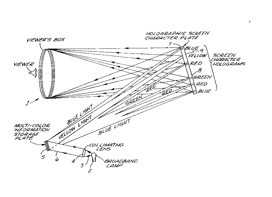
Fig. 1 shows a diagrammatic view of a preferred
embodiment of a holographic data retrieval and projection
system, generally designated 1. The system includes
broadband light source 2. Light source 2 produces white
light rays 3 that pass through collimating lens 4 and then
strike information storage plate 5 in the form of
collimated beam 6 of white light. For example, this lamp
can be an ANSI standard 1874 10-watt, tungsten-filament
lamp. Lens 4 has a sufficiently long focal length to make
the lamp filament appear nearly like a point source so that
collimated beam 6 has a small cross-section.
Information storage plate 5 diffracts various
colors of light from incident light beam 6 into the proper
locations of characters on screen character storage plate
7. Thus, green incident light is diffracted by storage
plate 5 entirely towards green diffracting characters 8 on
storage plate 7. Yellow light is diffracted toward yellow
diffracting characters 9 on storage plate 7, and so on. In
many displays, such as those on an automobile instrument
panel, the actual percentage of display area taken up by
characters and objects such as needles is small, say less
than 5%. Plate 5 advantageously directs all the light to
the appropriate characters, thus achieving extremely
efficient utilization of available light.
200Z9~0
1 Plate 5 includes several holograms, each designed
to diffract light over a predetermined, desired spectral
bandwidth. The holograms can lie entirely within a single
gelatin layer, or can consist of a stack of gelatin layers,
each including one or more holograms. Plate 5 can consist
of a large number of holograms, each having a desired
narrow spectral bandwidth or a smaller number of holograms,
each having a desired, broader spectral bandwidth. If the
spectral response bandwidth for each hologram is
sufficiently distinct from the others in the wavelengths
the hologram reflects, the device performs better than if
one or more holograms diffracts light whose bandwidth is
outside the desired predetermined bandwidth for that
hologram.
lS Fig. 2 shows a diagrammatic view of a second
embodiment of a holographic data retrieval and projection
system, generally designated 20. Here, broad bandwidth
lamp 21 produces uncollimated white light beam 22. Lens 23
collimates light beams 22, producing beam 24 of collimated
white light. White light beam 24 strikes first holographic
information storage plate 25, which diffracts some of the
light. Plate 25 transmits some incident light to second
holographic information storage plate 26, which also
diffracts light toward holographic screen character plate
27. The system illustrated in Fig. 2 functions in the same
way as the system in Fig. 1, except that the holograms in
plate 26 are tuned to respond to wavelength
20029~
1 regions that plate 25 transmits. In this way, as much as
70% to 80~ of the light incident on information storage
plates 25 and 26 can be diffracted to screen character
plate 27.
In principle, information storage plates 25 and
26 focus diffracted light onto screen character holograms,
which produce sharply defined characters at the image
plane. When the screen character image plane coincides
with the plane of the screen character holograms, the
images are sharply defined. However, when the images do
not lie in the plane of the screen character holograms, two
effects tend to blur the focused characters, namely, (1)
the extent to which the light source is not a perfect point
source, and (2) chromatic dispersion resulting from the
tendency of a hologram to diffract each wavelength of light
lying within its response bandwidth at a slightly different
angle, thus causing a rainbow-like spread of the image.
However, a lamp with a small filament such as the ANSI 1874
lamp provides a light source that approximates a point
source sufficiently to produce negligible image blur.
Further, designing the hologram fringes to lie nearly
parallel to the surface by making the diffracted angle
about equal to the incident angle minimizes chromatic
dispersion. Each hologram can be tuned to a narrow
spectral response bandwidth to reduce image blur further.
However, to achieve maximum image brightness, a larger
ZOOZ9~0
11
1 number of holograms are required to cover the spectrum of
light from the light source.
For most applications sufficient blur remains in
the image diffracted from the information storage plate to
make this image unacceptable for direct viewing. The
hologram screen characters provide a sharp outline of the
symbols, not the light from the information storage plate
itself. Thus, the information storage plate provides a
spotlight focused narrowly on each screen character. Each
spotlight can be a predetermined, desired shape. To reduce
alignment requirements between the information storage
plate and the screen character plate, each light spot can
be somewhat larger than its corresponding character on the
screen character plate. However, the greater the mismatch,
the greater the reduction in optical efficiency and image
brightness.
Fig. 3 shows that light 28 diffracted and
reflected from the information storage plates shown in
Figs. 1 and 2 strikes an area surrounding a character 29
such as the numeral "5" on information storage plate 27.
The screen character is a reflecting, diffracting optical
diffusing screen made in the shape and size of a desired
static character. The screen character diffracts light
lying within a wavelength band which includes the incident
light. The diffracted light forms a uniform, well-defined
cone of diffuse light such as cones 30 and 31, and reflects
these cones toward a viewer. If the viewer's exit pupil is
2002990
12
l sufficiently small and sufficiently far from screen
character plate 27, the screen character hologram focuses
light only into that narrow pupil. Thus, the screen does
not scatter light in all directions, but scatters light
very directionally, resulting in very bright images. Any
light that is not diffracted from screen 27 passes through
screen 27 and is absorbed by light-absorptive material 32.
Fig. 4 shows screen character hologram 33 that is
tuned to diffract white light by having green, red and blue
spotlights from the information storage plate illuminate a
stack of green-diffracting, blue-diffracting and
red-diffracting screen characters imposed atop one another
at 34 to produce a cone of well-defined white light 35.
Fig. 5 shows the effect of chromatic dispersion
upon broadband incident green light beam 39 on broadband
green screen character hologram plate 40. Reflected light
beam 41 is not of a single wavelength, but lies within a
spectral band. Chromatic dispersion causes the diffracted
light from the screen character to comprise a fan of
diffuse cones. However, since the image lies within the
same plane as the holographic film, the image resolution is
unaffected by chromatic dispersion. The dispersion causes
a rainbow-like effect at the image only at the outer edges
of the viewer's eyebox.
Fig. 6 shows an effect made feasible by
illuminating the screen character holograms with a narrow
band beam of light projected from a narrow band information
Z0029~0
13
1 storage hologram. In these circumstances, the positioning
of characters on the screen character plate can be less
precise because chromatic dispersion problems are smaller
with such narrow band beams of light. Such beams also
permit the use of three-dimensional characters. Further,
if an image is projected to a viewer by a system that
suffers from field curvature, the curvature can be
compensated by opposite field curvature in the surface of
plate 42. Under these circumstances, the screen character
images 43 and 44 do not lie in a plane, but on a curved
surface 45.
Fig. 7 shows a variation of the systems of this
invention to permit display of changing information. Here,
the holographic information storage plate is a rotatable,
translatable disc 46 carrying a plurality of stored
holograms such as holograms 47 and 48. Each position of
the rotatable, translatable holographic information storage
plate produces a different diffracted image, and projects
that image 49 onto holographic screen 50. Screen 50
diffracts this light in the form of light cone 51.
On an automobile instrument panel, the warning
lights, the speedometer analog or digital reading, and the
odometer reading are all changing information. To display
this changing information, light is directed onto rotating
or translating information storage plate 46. Each position
of the speedometer needle, for example, can be stored in a
separate hologram on plate 46. Plate 46 rotates in an
2002990
14
1 amount proportional to the speed of the automobile. The
incident light beam illuminates the correct storage
hologram on plate 46, which projects the correct needle
image onto screen character plate 50. In the center of
screen character plate 50 is a screen disc designed to
diffract any needle image focused on the screen. The
holograms in the storage plate can be made to have a narrow
bandwidth so that the resultant needle image on the screen
character plate 50 is sharp and well-defined.
Fig. 8 shows another system for displaying
dynamic information using liquid crystal display panels.
In Fig. 8, light beams 52 are incident on certain portions
of information storage plate 53 covered by light valve
material. The holograms under this light valve material
are designed to diffract light to various warning symbols.
Only when a particular segment of light valve material is
electrically activated to be in the "open" position will
light pass through, diffract from the information storage
plate, pass back through the light valve, and be directed
to the correct warning symbol on the screen character plate
54. Alternatively, the holograms, such as holograms 55 and
56 on plate 53, can be always in the "open" position, and
the light valve can be placed above the row of green
warning characters, such as characters 57 and 58 on plate
54. For added contrast, light valves at both storage
plate 53 and screen character plate 54 can be used
simultaneously.
200Z9~0
1 The resulting displays have high brightness and
contrast ratios yet consume little electrical power.
Because lamp lifetime is dependent on power consumption,
the low power requirements of these image sources results
in long lamp lifetimes. The use of light valve material
permits the entire display to be static increasing
reliability. Further, the image source is lightweight
and compact, an important advantage in displays in
transportation vehicles having limited access to power
outlets such as automobiles, planes, helicopters, ships and
submarines.
Figs. 9A and 9B show preferred methods for making
the information storage hologram plate. Fig. 9A is an
exposure system for exposing a silver halide screen 66 for
use in the information storage hologram exposure system.
Exposure beam 68 is a collimated laser beam at a wavelength
to which the unexposed silver halide screen 66 is
sensitive. Beam splitter 70 delivers part of the beam
through convex lens 72, which products a divergent beam.
Gaussian apodizer 74 is positioned on the divergent beam
path. Beyond the apodizer, collimating lens 76 produces
broad beam 78 directed to screen 66. That portion of
exposure beam 68 which passes through beam splitter 70 is
reflected from mirrors 80 and 82 to a flashed opal screen
84 covered with a mask hologram opening in it. The flashed
opal screen 84 is on a line substantially normal to the
center of screen 66, and produces a diffuse beam with a
200Z990
16
l spherical wave front. The result is an exposure of the
silver halide screen to a standing wave interference
pattern of the two beams.
After the exposure, screen 66 is developed and
used in the memory element exposure system 86 of Fig. 9B.
The exposure system is the preferred system for exposing
the green information storage hologram.
In Fig. 9B, a 514.5 nm argon laser beam 87 is
incident on a beam splitter 88 which reflects portion 89 of
the beam, and transmits the rest 90 of it. Beam portion 89
reflects off two mirrors 91 and 92 and through a spatial
filter onto plano-convex lens 94 which collimates the
light. Directly beyond collimating lens 94 is silver
halide diffusion screen 95 of Fig. 9A, which diffracts the
light through predistorted information reticle 96 into a
focused diffuse spot located at the surface of DCG
holographic plate 97. Second half 98 of the split beam is
projected from spatial filter 99 through collimating lens
100 and onto DCG plate 97, where it interferes with beam
101 from the silver halide diffuser to create standing wave
patterns, which are recorded as a reflection hologram in
the DCG plate.
Since the diffracted image direction of the
hologram changes with changing playback wavelengths, the
reticle image should be predistorted during exposure at the
exposure wavelength. The result is, that for playback at
the playback wavelength, the image will be rectilinear.
2002990
l To minimize exposure/playback problems, it is desirable to
select an exposure wavelength close to the playback
wavelength. Preferably, these methods use the 488 nm line
of the argon laser for violet and blue holograms, the 515
nm argon line for green and yellow holograms, and the 647
nm krypton laser line for orange and red exposures. DCG is
the preferred holographic film for the argon laser
exposures because of its low-scatter properties and large
dynamic range. For the krypton exposures, either
dye-sensitized DCG, photopolymer film or other films may be
used.
In the exposure system of Fig. 9B, silver halide
diffusion hologram 95 is used because it forces a greater
amount of light to DCG plate 97 than would a conventional
diffusing screen, resulting in higher exposure intensities,
and consequently shorter exposure and stabilization times.
Figs. 9A and 9B show the exposure system for green
information holograms. The exposure systems for the blue
and red information storage holograms is similar, except
for different laser wavelengths.
In Fig. 9B, if desired, one could use a
conventional diffusing screen instead of silver halide
holographic screen 97. This would require the beam
incident on the lens/diffuser/reticle combination to be
aligned with the output diffuse beam, as shown in Fig. 9B.
Fig. 10 illustrates a preferred method for making
green characters on the holographic screen character plate.
Z002990
18
1 Similar methods for the blue and red screen characters
use the blue 488 nm argon line and the red 647 nm krypton
laser line.
In Fig. 10, argon 515 nm beam 102 is split by
beam splitter 103. Half of beam 102 is projected by
spatial filter 104 through a collimating lens and diffuser
105 onto DCG plate 106 sandwiched between two identical
information reticles 107 and 108 containing the screen
characters. The diffusing screen may be either a
conventional screen such as ground glass or flashed opal,
or preferably a silver halide diffusion hologram which is
exposed in a manner similar to that shown in Fig. 9A. The
other half of beam 102 is projected by spatial filter 109
through focusing plano-convex lens 110 placed next to the
screen reticle/DCG plate/screen reticle sandwich
108/106/107. The two beams interfere at the DCG plate,
creating a standing wave which is recorded as a hologram in
DCG plate 106.
Fig. 11 shows the use of the system of Fig. 1 in
a diagram of a virtual image display system in an
automobile. Light passes through optical fiber 60, and is
directed onto collimating lens 61. Lens 61 transmits a
narrow width beam 62 of highly collimated light onto
information storage plate 63. Light reflected from storage
plate 63 in the forms of beams 64, 65, 66, 67, 68 and 69 of
distinct colors strikes holographic screen character plate
70, is diffracted onto metallized or dielectric folding
Z0029~0
19
1 half-mirror 71 along path 72, and is reflected to the
surface of metallized or dielectric aspheric combiner 73.
Images reflected as beam 74 then pass to the viewer.
In this system, a 10-watt, 1874 tungsten-filament
lamp produces an image brightness of 8600 foot Lamberts for
a white symbol at the viewer's eye for over a one hundred
hour lifetime. However, because there is more than enough
image brightness at 10 watts, by operating the light at
only five watts of power consumption, the lamp life is
extended to 21,000 hours and image brightness is still a
more-than-adequate 1700 foot Lamberts.