Language selection

Search

Patent 2003269 Summary

Third-party information liability

Some of the information on this Web page has been provided by external sources. The Government of Canada is not responsible for the accuracy, reliability or currency of the information supplied by external sources. Users wishing to rely upon this information should consult directly with the source of the information. Content provided by external sources is not subject to official languages, privacy and accessibility requirements.

Claims and Abstract availability

Any discrepancies in the text and image of the Claims and Abstract are due to differing posting times. Text of the Claims and Abstract are posted:

  • At the time the application is open to public inspection;
  • At the time of issue of the patent (grant).
(12) Patent Application: (11) CA 2003269
(54) English Title: SYSTEM TO SENSE AND DETERMINE THE PRESSURE EXERTED ON A FOOTBOARD OF AN APPARATUS FOR FOOTPRINTS MEASUREMENTS
(54) French Title: SYSTEME POUR PERCEVOIR ET DETERMINER LA PRESSION EXERCEE SUR LE MARCHEPIED D'UN APPAREIL DESTINE A MESURER L'IMPRESSION D'UN PIED
Status: Deemed Abandoned and Beyond the Period of Reinstatement - Pending Response to Notice of Disregarded Communication
Bibliographic Data
(51) International Patent Classification (IPC):
  • G01L 1/14 (2006.01)
(72) Inventors :
  • ZUCCHINI, FRANCO (Italy)
(73) Owners :
  • IL PODOLOGO DI TAURISANO CLAUDIA & C. S.N.C.
(71) Applicants :
  • IL PODOLOGO DI TAURISANO CLAUDIA & C. S.N.C. (Italy)
(74) Agent: ROBIC, ROBIC & ASSOCIES/ASSOCIATES
(74) Associate agent:
(45) Issued:
(22) Filed Date: 1989-11-17
(41) Open to Public Inspection: 1990-09-03
Availability of licence: N/A
Dedicated to the Public: N/A
(25) Language of filing: English

Patent Cooperation Treaty (PCT): No

(30) Application Priority Data:
Application No. Country/Territory Date
5125-A/89 (Italy) 1989-03-03

Abstracts

English Abstract


ABSTRACT OF THE DISCLOSURE:
A system is described herein for sensing and determining the
pressure exerted on the footboard of a podiatric apparatus by the
feet of a person, so as to measure the footprints thereof. The
system utilizes a plurality of sensors distributed uniformly on
the footboard and beneath a layer of flexible material, such as
rubber. The sensors are connected to a Multiplexer device, to an
analog/digital converter, to a programmed calculator which
translates the pressure data into visible and/or readable values.
The sensors may also ho subdivided into a plurality of strips in
order to accelerate and shorten the process involved.


Claims

Note: Claims are shown in the official language in which they were submitted.

WHAT IS CLAIMED IS:
1. System for sensing and determining the pressure exerted on
the footboard of a podiatric apparatus for the measuring of
footprints, which comprises: a plurality of capacitive sensors
uniformly distributed upon the footboard; a layer of elastic and
flexible material overlying said sensors for the transfer of
pressure from the feet of a person to said sensors; at least one
matrix scanner unit connected to said sensors; an analog/digital
converter connected to said sensors; and a programmed calculator
connected to said converter for the translation of pressure data
into visible and/or readable values.
2. The system according to Claim 1, wherein said censors are
fixedly connected to a rigid supporting platform and have one
electrically conductive surface thereof contacting said overlying
layer, on which layer rest, directly or through an interposed
second layer of electrically conductive material, said feet of a
person for the measurement of the footprints by means of the
determination of the instantaneous pressure exerted on said
sensors.
3. The system according to Claims 1 or 2, wherein said sensors
are subdivided into a plurality of strips, each strip having a
plurality of sensors connected to a matrix scanner unit and,
through at least one analog/digital converter, to a programmed
calculator for the translation of pressure data into visible
and/or readable values.
- 5 -

4. The system according to Claims 1, 2 or 3, wherein each
sensor comprises an electrically conductive rivet, attached to
said rigid supporting platform and having one surface thereof
contacting the overlying layer of elastic and flexible material,
said rivet being connected to a resistor and to a diode, one
terminal of said resistor receiving a signal of a predetermined
frequency, one terminal of said diode issuing a rectified voltage
of value proportional to the pressure exerted on said rivet by
the feet resting on said footboard.
- 6 -

Description

Note: Descriptions are shown in the official language in which they were submitted.


2~3~6~
S P E C I ~ I C A 1' 1 0 N
T lTLE:
A SYST~M TO 5E;~SE AND DETER~lINE THÆ PRFSSURE J~XERTEi~ ON A
F(:)OTBOAR[) OF Al~ ~PPARP~ S FOR E`OO~PRINTS MEASUREMENTSo
FIELD OF TH?. INV13NTIO~
The present inven~ion r~latss, .in general, to apparatus ~or
sensing ~nd deterrnining footpLints and, more particu].arly, it
relRtes t~ a foot~o~rd ~o~ ~uch appar~tus, ~he footboard
incorporatin~ means ~or t~e instantaneous d~tsrmination of
pressure exerte~ by the feet o~ ~ p~rson upon Ste~Qirlg on ths
footboard for the definiton and mi~asucc-mPnt o~ the foot~rints,
bo~h under dynamic and s~atic cond.itions.
BRX~F PES~RIPTION O~ THE INVE.~TION:
It is belie~ed this to be the ~irsi time that such a systern o~
determin~tion o~ podiatric pressur~ m~surement has been employed
~nd adopted in meas~ring ~oo~prints and it~is, consequently, the
main scope of this invention to provide a footbo~Fd ~or podi~tric
apparatus employed in th~ deterrnination of ~ootor.ints, ths
footboard incorporat~ng ~ sy;tem o~ c~-~acitive s~nsors actuated
upon by the hurnan body, spacific~l~y the ~aet, through a
flexible r elas~ic, electric~lly insul~ting ~lement, such ~s
ru~b~r, ~nd controlled by pro~ramm~ble calo~l~ting means.
I~ is, ~he~efo,;e, possible to obtain the ~ial advantRge of
utili~ing ~ foot-supporting mat~rial which is diel~ctric in
na~ture and of siTnplifying the d~si~n of the footbo~rd, wtiilQ
assi~ing at the same time the ef~iciancy of the board and the
n~Rximi~ation of precision of podiatric pressure determinati~ns,
both under dynRmic and static conditions.
-- 1 --
. ~

The present inventlon l~el~t;es, tnerefore, to a novel system
for the ~eter~ination of the press~re exerted upon the ootboard,
i~ ~rrnr~l?n~o with the recita-l;ion ln tne accompanying ~laim 1
THE DR~WINGS:
Greater details of the pres~nt invention will become more
evident from the I`ollwing description the~aof in conjunction
w~th the accompanying dr~wings, in which:
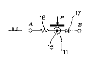
Figure l is a sche~tic illustration o~ ~he system utilized in
one o~ the Sensocs employed in the invention;
~ i~u~e 2 is a block i~lust~a~ion of the system of sensing and
determining the pre~sur~;
Fi~ur~ 3 illu~trates the connec~ion of a few of the sensors to
a matrix scanning unit;
Figure 4 is a perspective vi~ Q~ the as3em~lo~ footboard with
a section o~ 5ensors and ~heir position visible ther~ini
Figure S is an enlarye~d vie~ o~ the distribution of a nu~ber
of sensors on the footboard; an~
~ igure G is another enlargsd, sectional vie~ oE t.he ~ootboard
with its re~pec~iYe sensoes.
DETAI~ED ~ES~RIP~ION OF 'rHE INV~I~T~O~l:
~ he system oE the present lnvention substantially utili~e~ a
matrix of sensors ll mountsd on a .ootboard l~ o~ large
dimnnsions, onto which it is ,oossi~le to ste~, in order to effec~
the m.~sure~nent of footprints through the sensing and
determination o~ the instantaneous pressu~ P exerted by the feet
o~ ~ person on the footboard itsel~ o~, more pre~isely, on the
s~nsors ll.
The s~nsors ll ~re mounted on a rigid, supporting platform 13
and are d~spo$ed in ~n orderly manner (se~ figur~s 4 and 6)
bencath a 1.e~ible layor 14, such as, ~or e~ample, of rubber, or
. , ' '' ", ' ,' ~
,',.
., : : , ' :

~3~
alt~rna~ively, ~nveloped within or applied to a layer of elastic,
dielectric material or other supporting el~ment 1~'.
~ ach sensor 11 comprises a metallic rivst 15, serving as an
electro-cond~ctor, fixsd to the rigid supportin~ platform 1~ o~
the ~ootboard 12 and having one sur~ace thereof contacting ths
o~erlying ~lexibl~, elastic l~yer 14. Conn~cted to tha rivet l5
there are a ~esisto~ 16 ~nd a ~iodQ 17 inserted ~ithin an
appro~riate circuitry 19, ~s illustrat~d in figure 5 of the
accompanying drawings.
Each sensor, in ~ssence, functions by exploiting ths
c~pacitive ef~ect created by the combination rubber~rivet-human
body. Such Gom~ination may be visuali~ed as and compare~ to a
capacitor with the plates formed, respectively, by the rivet and
the human foot. The rubber l~ye~ interposed bet~ecn the rivet and
the foot serves to obtain - eventually ~lso thro~lgh the
~6istancs of an elect~o-conductive lay~r - ~he v~riation in the
distance ~tw~en the ~wo plate~ (rivet-foot), variation that
,
depends of ~ourse on the amount or d~gree of prsssure appli~d by
the ~oot. ~hus, ~hen a person stands upon the footbo~rd, the
ru~ber is compressed in rnanner directly p~oportional to the
pressur~ exerted thereu~o~ by the,feet. Since the c~pacity of a
condens~ va~ies in mannor proportional to the distance bet~een
it3 plates, the~system of the in~ention, com~arably t~ereto, wiIl
have ~xactly the same effects as 3 variable cap~cit~nceO
In ~igure 1 o the ~com~anyin~ dra~ings, there is illustratQd
- schematically - the idea o th~ sensor of the invention,
~he~ein thRre are sho~n - ~s in figure 6 - and indicated with 15,
16, 17 and P, re~pectively, the rivet, the resistor and the diode
and the pressure a~plicd on the rive~. If a signal o~ a given
re~uency i5 applied to point ~ of the system and a p~essure P is

2~6~3;~6~
appli~d t~ ~he rivet 15, the sensing circuit practicslly
~unctiorts as a volt~ge T;ectifier, because at point 8 o~ tlle
~ystem there is obtaine~, t~rou~h diode 17, ~ rec~ified volt~g~,
the amount of which is proportional to the di~tance bet~een the
foot and the rivet an~, there~oce, to ~he pressure exerted by the
Poot, throu~h the layer 14, on the rivet 15.
~ he foot~oard is, ~hus pro~ided wi~h a plurality o~ sen~ors 11
of this type. Th~ir nurnber ~ay be, ~or example, as larg~ as 4~8,
so as to allow th~ determination of pr~ssure at eve~y point o~
~he footboard sur~ace. All s~nso~s ace connected - see figur~s 2
and 3 - to at least one matrix scanner unit, such as ~
Multl~lexer, 19, which in turn is conne~ed; through an adequate
number of analog~digital ~onverters 2~, to g calculator ~1 so
programmed th~t it rea~s the instantaneously ds~ermined pressure
v~lu s, c~rries Gut the necessary calculations and displsys on a
monitor and~or a ~rinter all ~ata ~slating to the foot~rints to
be meaaured.
It is to ~ observed ~150 that th~ mstrix scanner of the
ssnsors ~y b~ subdivided into strips - a suitable n~mbe~ could
bs 5even - each strip composed, in this instance, of 704 set-sors.
With t~is arrangeTnent, it is possibls to rea~, with eac~
ac~uisition of da~s, concurrently the sensoTs of each strip, thus
reduci~g to one seven~h the ov.?rall ti.me required for a total
s~nnin~ o the sensocs.

Representative Drawing
A single figure which represents the drawing illustrating the invention.
Administrative Status

2024-08-01:As part of the Next Generation Patents (NGP) transition, the Canadian Patents Database (CPD) now contains a more detailed Event History, which replicates the Event Log of our new back-office solution.

Please note that "Inactive:" events refers to events no longer in use in our new back-office solution.

For a clearer understanding of the status of the application/patent presented on this page, the site Disclaimer , as well as the definitions for Patent , Event History , Maintenance Fee  and Payment History  should be consulted.

Event History

Description Date
Inactive: Abandon-RFE+Late fee unpaid-Correspondence sent 1996-11-18
Inactive: Adhoc Request Documented 1996-11-18
Time Limit for Reversal Expired 1995-05-17
Application Not Reinstated by Deadline 1995-05-17
Deemed Abandoned - Failure to Respond to Maintenance Fee Notice 1994-11-17
Inactive: Adhoc Request Documented 1994-11-17
Application Published (Open to Public Inspection) 1990-09-03

Abandonment History

Abandonment Date Reason Reinstatement Date
1994-11-17
Owners on Record

Note: Records showing the ownership history in alphabetical order.

Current Owners on Record
IL PODOLOGO DI TAURISANO CLAUDIA & C. S.N.C.
Past Owners on Record
FRANCO ZUCCHINI
Past Owners that do not appear in the "Owners on Record" listing will appear in other documentation within the application.
Documents

To view selected files, please enter reCAPTCHA code :


To view images, click a link in the Document Description column. To download the documents, select one or more checkboxes in the first column and then click the "Download Selected in PDF format (Zip Archive)" or the "Download Selected as Single PDF" button.

List of published and non-published patent-specific documents on the CPD .

If you have any difficulty accessing content, you can call the Client Service Centre at 1-866-997-1936 or send them an e-mail at CIPO Client Service Centre.


Document
Description 
Date
(yyyy-mm-dd) 
Number of pages   Size of Image (KB) 
Drawings 1990-09-03 2 80
Cover Page 1990-09-03 1 18
Abstract 1990-09-03 1 17
Claims 1990-09-03 2 44
Representative Drawing 1990-09-03 1 2
Descriptions 1990-09-03 4 141
Fees 1993-11-15 1 38
Fees 1992-11-17 1 39
Fees 1991-09-27 1 36