Note: Descriptions are shown in the official language in which they were submitted.
20033iS
TITLE: DENTAL PRODUCT COMBINING A REAMER TOOL
AND ANCHOR POST
BACRGROUND OF THE INVENTION:
The present invention relates to a combination
product which combines the utility of a tool and a prosthesis
support post for use in dentistry, and more particularly to a ~ -
product which first can be usèd as a dental tool which provides
for the drilling of a bore hole and for the forming of lateral
undercuts along the interior longitudinal surface of the~bore
hole into a tooth canal, and which can be rotated by a dental
-~ handpiece associated with a dental drill, and at least a
portion thereof can then be maintained within its own drill~
~ hole as an anchor, or support, post for a dental prosthesis.
'~ It is well known in the dental field to provide a '~
drill tool bit for forming a bore hole through the root canal ' '-'
of a tooth. It is also common to grind away~the upper surface
15~ of~the tooth, using a dental grinding tool to provide space for '"'~
a~denta-l prosthesis to be anchored to the tooth via an anchor ~- '` -`
post ext-nding into and cemented within the bored out root
canal.~ Such denta} anchors are generally cemented into the
bore~h'ole~and in some cases the anchors are provided with
20~ ~n~dulating~1ateral~surfaces to further assist in securing the
anchor to the cement.~ It~has been found, however, that the
;~ ~sècurity!of~ the~den~allprosthesis may be comp~omised by a
failure of the cement holding the anchor in the bore, as well
as by~th-~diff1culty~of~6eating the prosthesis around a
' ~25- s~pro~ecting portion~of the anchor and onto the top of the tooth.
Furthér~problems can be created by the use of an improperly
-~'' ~ mat~hèd~anchor post~for the r-amer diameter, especially where a '
pa8sive~anchor post is desirable.
20033~
SUMMARY OF THE INVENTION
Accordingly, it is an object of the present inventlon
to provide a dental tool which combines the effectiveness of a
bore drill, or reamer, and an undercutting routing tool, and
s can act as the prosthesis anchor post, to provide improved
accuracy of fit and for the security of the cemented anchor
within the tooth. It is a further object of the present
invention to optimally provide on the tool a counterboring
portion to enlarge the outer end of the bore. It is a further
object of the present invention to provide all of these effects
by a single tool, which can then be reformed into the anchor
post, thus permitting not only efficiency in the number of
tools required, but also simplifying the problem of maintaining
the accuracy of fit and the integrity of, and desired mutual ~
15 relationships between, the bore hole and the cemented anchor ~ -
post in the bore hole.
These and other objects are achieved in accordance
with the present invention wherein the combination dental
device includes a first holder end portion designed to be
receivable in a dental tool holder, such that the dental tool
- holder can rotate the dental tool; a second drilling, or
reaming, end portion tapering longitudinally endwardly to a
minimum effective diameter at the second end and providing an
- ~ axially facing cutting surface for forming a bore of sufficient
diameter in a tooth of a patient, upon rotation of the tool, to
~- receive an anchor post; a drill shank portion extending from
th- drilling end portion towards the holder portion and
pr`eferablylincIuding at le'ast two alternating~longitudinally
extending shank sections, the first drill shank section having
}aterally facing cutting surfaces and a relatively larger
e~ffective diameter, and the second drill shank section having a
smsller effective diameter and a non-cutting surface such that
; the application of laterally directed force to the tool while
the tool is being rotated within the bore of the tooth provides
~for the routing out of notches, or undercut surfaces, along the
int-rior of the bore in the direction of the laterally directed
: ~ .
force. The drilling end of this tool is intended to include
means for forming a hole by drilling, as well as reaming means
to enlarge the tooth root canal.
There is further preferably provided, at a portion
intermediate the drill shank portion and the first holder end,
a divergent counterbore drilling section capable of forming an
enlarged bore diameter at the outer end of a bore hole in a -~
tooth, and a planar grinding surface ~ ;~
The first holder end portion of the tool is designed
to be removably secured to a conventional dental handpiece so
as to be rotatably driven from the handpiece. The tool is to
be secured into the handpiece such that it will maintain its - -: i
position upon the application of longitudinal force exerted
toward the second drilllng end of the tool and upon the
IS exertion of lateral force while the tool is being rotated as
described in the above-identified copending application.
Immediately adjacent to the maximum diameter end of
:, ",,:, -
the counterbore, and extending towards the holder end, is aprosthesis core support portion which preferably has a maximum
diameter at least about equal to the maximum effective diameter
; of th- counterbore.
In one embodiment, where the prosthesis core support `~
portlon dlameter isi not ~;gnificantly larger than the maximum
effQctive diameter of the counterbore, a prosthesis core can be
5~ bui1t up~around the~core support portion, which may have to be
= ned~by~removing th- holder end, if necessary. In another
embodim~nt~, the maximum core support diameter is significantly
` ~ ~làrger than the counterbore and an e.g., all metal core unitary
with~the anchor post can be prepared by working and shaping the ~-
~core~support portion by known means. In this latter situation,
thè axially~facing~surface of the core siupport portion i8 a
planar grindlng~surface~for cutting down ànd levelling the
t ~ h~surface~and surrounding the counterbore to support the
proi6ithe~
35~ Th--core anchor section preferably tapers inwardly
toward-~the holder end and can be rippled, or scored, to
;pres~nt undercuts to improve adhesion o~ the core anchor `
20033iS
6ect~0n to composite or cement materlal forming a core for the
immediate support of a crown, or prosthesis, above the tooth
stub. If the core anchor section has a diameter sufficient to
form a unitary core, the undercuts are to be added after the
s section has been cut and shaped to accept the crown prosthesis.
After the bore hole is reamed, and routed out to form
the undercuts, the reamer is replaced into its self-drilled
hole, and cemented into place as an anchor post. The holder
end extends above the bore, and serves as a useful handle for
manipulating the anchor post until the post is cemented in
place.
Any pre-formed undercuts in the core anchor section
are to be limited in depth so as not to reduce the structural
strength of the reamer such that it would not be able to
lS withstand the stress of boring. After the drilling end is
cemented into the bore hole, the portion protruding above the
bore hole can be trimmed and cut to the desired size using a
conventional edge grinder disk, for example, and undercuts can
be added.
The combination dental tool and post of the present
invention is to be used with a conventional dental tool
handpiece as providinq support and driving power for the
; dQvice. The size and shape of the holder end is thus
; neoQssarily limited by the requirements of conventional
25~ handpieces --
As used in the process of this invention, the drill
point, or reamer, is placed at the exposed root canal opening
of a tooth. The tooth has been reduced to approximately the
desired~height abov- the gum line by removing broken or decayed
dental material. The combined tool post is held by a
; conventional dental handpiece and the power applied to rotate
the tool at low speeds in a conventional manner, pressing
`downwardly against the tooth to bore out a hole of the desired
depth. This procedure is especially useful for preparing a
~tooth~for the placing of a crown on an anterior mandibular or
maxil~lary tooth.
; t
20~33~5
It is well known ln the dental field to select a
drill, or reamer, of a proper length and diameter to obtain the
desired si~e bore hole. For the present invention, however,
the length of the drill shank is preferably carefully
calibrated with the desired depth of the bore, as the drill
shank is preferably inserted substantially completely into the
bore hole, such that the counterbore portion of the tool forms ~-
a funnel-shaped enlargement of the entrance to the bore hole,
by reaming out a counterbore, and the planar grinding surface,
if present, can grind to a level plane the surface of the
tooth. In addition, the core post shank should extend above
the top surface of the tooth to form the central support for
the prosthesis core. The enlarged counterbore is preferably
provided at th~ zone of greatest stress, at the interface of
the ground down tooth and the crown.
After a hole is bored out to the desired depth, using
the preferred tool of the present invention, the tool is
withdrawn a short distance above the bottomed out position, and
lateral pressure exerted by the tool on the sides of the bore,
preferably alternately and only in the facial and lingual
d~rectlons. In this manner, the enlarged first shank sections
rout out laterally undercut notches at the spaced positions of
such first sections along the bore, in the preferred lingual
and ~acial directions. It is noted that the tool preferably
does not widen the cross-section around the entire
circumference of the inner bore in the tooth, but only
elongate~ those portions contacted by the cutting surfaces of
the first sections of the drill shank portion in the direction
in which lateral pressure is exerted.
~he combination tool/post is withdrawn from the bore
hole and disconnected from the handpiece. The drill shank is
then inserted back into the bore, Ieaving the core post shank ~ :
~; extending beyond the tooth. Cement is packed into the bore ~ ;
hole with the post in the conventional manner, but surrounding
the anchor post, and extending into the bore hole undercuts, ;~ -
securing the post in the bore hole; the holder end portion is -`
then usually cut off from the anchored post at the desired ~ -~
.
21)0331S
length. The core anchor section, if large enough, can be
shaped and cut to the proper size to serve as a unitary core
for a crown. The security of the cemented seal is improved by
the interaction between the routed out undercuts in the bore
5 and the varying diameter along the drill shank. -
Further details of the present invention are shown in
the accompanying drawings, by way of example and not by way of
exclusion. Many portions of the invention or the context
therefor are shown in schematic representation, where greater -
detail is unnecessary, as it will be apparent or well-known to
those skilled in the art. Referring to the accompanying
drawings: -
200331S
7 . ;
BRIEF DESCRIPTION OF THE DRAWINGS .
Figure 1 is a side elevation view of one embodiment
of the present invention; . ~:
Figure 2 is a cross-section view along line A-A of
Figure l;
Figure 3 is a cross-section along line B-B of Figure
l;
Figure 4 is a cross-sectional view of the embodiment
of Figure 1 taken along lines C-C;
Figure 5 is a cross-sectional view of the embodiment
of Figure 4 taken along lines D-D;
Figure 6 is a cross-sectional view of the e~bodiment
of Figure 4 taken along lines E-E;
Figure 7 is a cross-sectional view of the embodiment
of Fiqure 4 taken along lines F-F;
Figure 8 is a perspective view showing a tool of the
present invention being held while rotating;
Figure 9 is a cross-section elevation view showing a
: tool of the present invention almost fully deployed within the
: ~20 bore o~ the tooth stub;
; Figure 10 is a side elevation view, in partial cross-
se¢tion, of a tool of the present invention held by a
conventional dental handpiece in the first staqe of the routing
proc-dur-:of the present~invention;
25~ Figure 11 is an elevation cross-section view of the :
dental tool of the present invention withdrawn from a fully
reamed~and~routed bore of a tooth (shown in cross-section) in:~
accordance with the present invention;
~ Figure 12 is a perspective view of a dental anchor : i``
:~ 30 :post being formed from the reamer-router tool in accordance
with the present invention; .
Figure 13 is an elevation cross-section view of a
::completed~tooth prosthesis, including the anchor post formed
according~to:the present invention;
~:~ 35 ~ Figure 14 is a side elevation view of another
-mbodim nt of the tool of the present invention in a handpiece;
-s 2003315
... ,, ;',',.
. . ...
Figure 15 is an elevation cross-section view showing
a unitary crown core, or supporting foundation, formed from the
embodiment of Figure 14, in a tooth. . -
. ' ,:- -~, ' .
. . .
. ~
-; ,- -, ~ ,
: - :
;,, ~, :
,;., .,.; ~. ~ -:
',~' ;. ~.,-,,:
,
Z00:~3~S
DETAILED DESCRIPTION O~ NTION
Referring to the drawings, a combination reamer tool
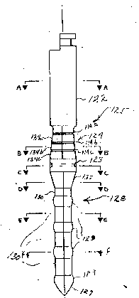
and post, indicated by the numeral 125 is shown having a
reaming, or drilling, first pointed end 127, a drill shank
portion, indicated by the numeral 128, comprising a plurality
of cutting and routing sections 129, separated by a plurality
of relatively smaller diameter shank stop sections 130.
Located immediately adjacent the innermost stop section 130 i~
the divergent counterbore section 132. Immediately adjacent the
maximum diameter of the counterbore section 132, and extending
axially towards the holder end 122 is a cylindrical core post
shank section 123, and immediately adjacent thereto, and
tapering inwardly towards the holder portion 122, is the
rippled or undercut core anchor section, generally indicated by
the numeral 124. A holder end portion 122 extends outwardly
from the core anchor post section 124.
The outer section of the holder end portion 122 is of
conventional design suitable for being secured to conventional
dental handpieces, and can be adapted for whichever dental
20 handpiece is to be used. ~
The cross-sections of the cutting portions 132, 129, `` -
127 are preferably substantially square. The cross-section of -~
the core post shank 123 is round as can be the cross-sections - -
of the~smaller diameter intermediate shank stop sections 130:
25 these latter sections are herein shown as square in the - `
drawings. -`
The cutting portions of the tool 128 of Figure 1,
include the lower drilling end 127, the counterbore portion -~
132, and the larger!'ro~ting shank sections 129. The smaller - ~ -
30 diameter shank stop sections 130 do not include a lateral ~`
cutting surface, such as are present on the routing shank ~ `
sections 129. The various cutting surfaces and the drilling
point end 127 can be coated with a hard, fine granular
substance, such as diamond dust. The cross-sectional views of
~35 Figures 6 and 7 show that both the routing sections 129 and the
intermediate, smaller diameter shank stop sections 130, are
ubstantially square in cross-section.
: ~ :
20033~S :
Both of the embodiments depicted in the drawings are
provided with laterally cutting routing sections 129, having an
outer surface forming a substantially continuous curve in an
axial direction, between two smaller diameter intermediate stop
sections 130. The curved cutting surfaces of the routing
sections 129 can be also optionally coated with hard, fine
granular material, such as diamond dust, if desired.
The combination tool and post 125 can alternatively
be formed having cross-sections of various other regular
polygons, as desired, the apices of the polygons in the routing
sections 129, drill point 127, and counterbore 132, providing
the cutting edges. Included within the scope of such polygonal
cross-sections are shapes having at least one curved side, such
as so-called half-round or quarter-round shapes. Preferably,
the polygons have no more than six sides. When the term
"diameter" is used for such polygonal cross-sections, it refers
to the "effective diameter", i.e., the diameter of a bore hole
cut by such sections rotating about a single axis. -
The core post shank 123 is substantially circular in
cross-section, being substantially cylindrical in overall
shape. The core anchor section 124 is substantially a
truncated pyramid in overall shape, having substantially square
cross-séctions, with the apices rotated about 45' relative to ~-~
the apices of the drill shank section 128. The undercut
25 portions 114, have a substantially reduced diameter, providing -;
for more secure adhesion to the core composite cement. --
If desired, the combination device of the present ;~
invention can be fabricated with marked segments, or score
lines, indicating units of length. For examplé, the segments
30 on the anchor core section, or the individual drill routing -
sections, can be formed to a specific length, e.g., 1 mm. This
permits readily cutting or grinding the drill or reamer to the
desired length by merely counting segments.
The initial reaming out of the tooth root canal is
35 carried out not only by the end drilling portion 127 but by the - ~; ~
leading routing ring section 129. ~ -
200331S
Referring to Figure 8, and to Figure 9, wherein the
combination tool of the present invention is located within a
bored hole, the tool 125, is operatively supported and held by -
a conventional handpiece, generally indicated by the numeral
S0. The handpiece is of a conventional type, which can provide
support and carry the driving power to the tool 125 to cause it
to rotate. The handpiece 50 can securely hold and mechanically
drive the tool 125, while being subjected to longitudinal
forces exerted axially into the tooth, during a reaming out '
10 operation, or while being subjected to force applied laterally, ~;
and against the lateral interior surfaces of the bore, during a
routing operation. Such hand pieces are well-known, and can,
e.g., be air- or motor-driven, or directly gear driven, by
straight or right angle'dental rotary devices.
Referring to Figurel14, a combination tool is shown,
generally indicated by the numeral 225, wherein the anchor core ~ ~'';'''
section 224 is substantially larger than that of the
'~ counterbore 232. A planar grinding surface 252 is formed -~
defining the edge of anchor core 224 and extending annularly
about the counterbore maximum diameter. The drill shank 228 is
;- ~' substantially similar to thàt of the first embodiment of Figure
and all~of the cutting surfaces 227, 229, 232 and the ~ ''''
grinding~surface 252 can be formed of similar hard materials
~and coatQd with the~hard~granular material, such as diamond~
~dust.~
In~carrying out the procedure in accordance with the
present~invention,~after the bore is fully formed in the tooth,
as~shown~by Figure 9, including an enlarged counterbore at the '~
top'~surface"'of/'thé'tooth,~'the 'tool 128 is lifted above its
~bottommost position, as shown in Figure 10, such that the
counterbore 132~is abov~e~the top surface of the tooth. ~Lateral ''~
pressure`~is~;Qxerted~from~the~handpiece 50 through the tc,ol 125
ag~in t the~inside;~of~the tooth bore, while the tool 125 is
contlnuous~ly~rotated~at~the~desired speed. SUch pressure is
35~ prè~erably~exerted successively in the lingual and facial
diréctions, such that the grinding rings 129 are forced against
the,~s~ ~ of~the bore, routing out undercut surfaces, or
2~)3315
notches, .along the surface of the bore in those directions.
The pressure is exerted first in one of the preferred
directions and then in the other of the lingual and facial
directions.
The router portions 129 are preferably approximately
25% larger in diameter than the second, lesser diameter stop .. ~
sections 130, such that upon fully routing out the undercut .;':'
notches, the notches have a major elliptical diameter :~:
approximately 50% greater than the original bore hole diameter. '.:.
10 The maximum diameter of the counterbore 132 is preferably at .. : ~
least 50% larger than that of the router sections 129, and the .'.
diameter of the planar grinding surface 252 is at least about :~' :
50% larger again. . . .l ':
A fully reamed and routed out reduced tooth T, from '~ '.. ~;
~;: 15 which the reamer has been withdrawn, is shown in Figure 11. ' .': ;
The reamer 125 is removed from the handpiece 50, and the .
portion:comprising the counterbore 132, the drill shank 128 and .'~
drill tip 127 is reinserted into the reamed and routed out - -~
tooth bore, as the anchor post base, as shown in Figure 13, and
~; 20 cemented in place. - ''--`.'
The anchor post base 128 is inserted into the
:pr-pared~.bore hol-, with cement to secure the anchor in place.
The~:~inherently accurate size relationship between the bore hole
and~.thè anchor post~diameters, permits this anchor post 128 to
;25~ b- readily~used a~ a:so-called "passive" anchor, wher- the post
néed~not~be~screwed in place into the bore hole. The post 128 :'~
merely~:drops passively, or is gently pushed, into the bore. As ' .'-
~:: shown:in~Figures 13 and 15, the larger diameter router sections '~
129~,~ 229 are'lnot ju~taposed with'the routèd out, undercut tooth . ~:'.'-~;.:.30~ bore~sections~B). In this manner, the cement has been found .'~
to mor-~securely hold the anchor post in place. ::.`~
Extending outwardly from the tooth bore is the core
~ ~.anchor~post, which~Gomprises the cylindrical core post shank:~ "
C.`~123 and~the convergent anchor 127 section 124, and the holder
.35~ nd;122, which:~anchors a tooth prosthesis, P. If necessary,
the protrùding~holder end 122 is cut down to the desired length --
beyond~the~surface of the bore hole, and to the desired shape,
20033~5
and then cemented integrally with a core to support the desired
crown prosthesis.
In Figure 15 there is depicted a crowned tooth
prepared with a unitary anchor post and crown core 228, 224,
made of an integral piece of material; the anchor core section
224 is shaped and sized (from its original shape shown in
dashed lines) to the core size shown in the drawing, by well
known dental fabricating means. This unitary core can directly -
retain and secure that crown prosthesis by being cemented to
the crown directly.
The present invention not only reduces the number of
individual items the dentist must keep in stocX and sterilize
for use, but also avoids the problem of a misfit between the
anchor post base and the bore hole.
Although the particular shape of the core anchor post
121 shown, is not a necessary feature of this invention, the
combination of the cylindrical core post shank 123 and the
undercut tapered pyramidal core anchor section 124, provides an
especially secure, core anchor post beneath a composite core.
The particular shape of the drill cutting 6egments
132, 128, 127 of this combination dental produGt is also not
critical to the invention. For example, any of the drill shank
embodiments described in the above-identified co-pending
application can be used with this invention, and can be used as
the anchor post base. A straight, constant diameter, drill
shank can be provided, if desired.
It is understood that the core anchor section 124 and - -
the core post shank 117, or the unitary core 224, need not be
made of thelsame material as the rest of thè combination ! ':
product, i.e., the holder end 122 and drill shank 128 (which is
inserted into the tooth bore). For example, titanium alloy,
or other hard and tough material, such as stainless steel, is
the materidl of choice for the drill shank 128, i.e., that
-~-; portion of a prosthesis anchor to be inserted into the tooth
~35 bore. The core anchor portions 117, 124, or unitary core 224,
however, can be formed of the same metal or of a softer, more
easily shaped material, such as a ceramic dental material, a
: ~ .
~: -, ... .
p
2()03315
.
14
polymer composite, or a ceramic/metal or polymer/metal .
laminate, or another metal, for example. The undercut core :
anchor section 124, or the unitary core section 224, should,
however, have sufficient torsional strength to withstand the
stress of rotary drilling. All of these anchor post materials,
as well as other materials well-known to the art, can be formed
as a unit with the drill shank and counterbore portion by well- ' :~ :
known means, such as welding, soldering, or casting or molding ~ .
together. - :
~' ~' ;'
~ .
.
.:
, ~ , .
'~, ~: : . . ,.,,:.